#help-with-arduino
1 messages · Page 43 of 1
 north kelp
 obsidian bolt
Short version: can't seem to get it into bootloader mode/upload to it anymore. I have a little namebadge I made with a lipo and a a couple addressable 7-segment displays and a trinket m0. It's been working well for a while now, but I wanted to change the code a bit, and plugged it in to my laptop to try and upload a change. The port was visible, but when I tried to upload I kept getting a could not find device error. So I tried to double-click the reset button. Now I get a green power led, a blinking red led, and a solid red dotstar
So I've definitely wiped my previous code, but I'm at a loss as to how to get it into a mode where I can upload to it again
I've disconnected the lipo for now to make sure it actually turns off when I unplug the usb
If I press the reset button, the dotstar blinks purple for a second and then stays solid red
So it seems like I'm either having a bootloader issue or a USB cable issue. I tried another cable, and another port, and verified that the cable can transfer files from my phone (so not just a power cable)
If I switch to another computer, I can get the RGB LED to turn green and it shows up as a port in Arduino IDE, but I still can't upload to it
 rocky igloo
@obsidian bolt When you say that you can't upload to it on the other computer, what happens when you try?
obsidian bolt
"No device found on cu.usbmodel1411" (Which is the port that shows up in the IDE as (Adafruit Trinket M0)
Is there anything specific I need to be setting for "USB Stack" or "Programmer" in the IDE?
USB Stack is currently set to Arduino, and Programmer is set to USBtinyISP
rocky igloo
As far as I know, the "Programmer" setting is just for burning bootloaders. It uses the bossac tool for uploading sketches when the bootloader is working. I'm looking for info on Arduino vs TinyUSB.
Wish I had something more to offer you but I don't have a Trinket M0 here, or Windows. Can someone else step in?
obsidian bolt
I have a non-M0 trinket and and ESP8266 feather at home that I could test with, but I'm currently on the road and only have this board with me 🙂
I'm on Mac, actually
I should try Windows real quick and see if that works any better
Weirdly, with the same cable and the same OS (10.12.6), one laptop sees the board (shows up in Arduino IDE and System Profiler under USB) and the other does not.
But even the one that sees the board currently can't upload to it
rocky igloo
Oops, I'm on Linux and saw stuff I didn't recognize and guessed Windows. Sorry, Mac.
obsidian bolt
Hmm, TRINKETBOOT showed up as soon as I switched to Windows. Might be a weird Mac driver thing
(Windows is running on a VM on the Mac, so it's not hardware or cable issue)
I guess I'll grab the Arduino IDE on Windows and see if I can upload from there
rocky igloo
Sounds promising!
obsidian bolt
Gonna take a while, need to install libraries and boards
Partial success, updated the bootloader and deleted some usb serial kexts for other board and FTDI's from my other Mac while I'm waiting for things to install, and now the laptop that couldn't see the board at all can see it
Still can't upload from either Mac though
 surreal pawn
did you try double-pressing the reset button and uploading once it enumerates as the trinketboot drive?
oh reading above your reset button didn't work?
 shy marten
@obsidian bolt Are you uploading directly from Mu, or are you manually copying the files using cp or finder?
surreal pawn
he's using arduino it sounds like given the questions
obsidian bolt
TRINKETBOOT showed up once I switched to Windows and reset
Trying to upload a sketch with Arduino IDE v1.8.10
shy marten
lol, forgot which chatroom I was in
obsidian bolt
I upgraded the bootloader from Windows, and then switched back to my Mac to try and upload the sketch
(Installing libraries on Windows so I can attempt to upload the sketch from there as well)
Progress! Works fine from Windows. Now I just need to figure out why I can see it but not upload sketches from Mac
surreal pawn
@obsidian bolt did you connect something to the reset pin on the trinket?
obsidian bolt
I don't believe so. I have a header on it, but it's not wired up to anything
Arduino IDE can see the port, and it resets it properly when I try to upload, but the actual upload fails
This is with verbose upload turned on
Oh well, I'll keep playing with it. At least I was able to update it from Windows for my Halloween costume :-). Thanks for the help!
surreal pawn
if you press reset twice to get trinketboot drive and choose the serial port again before uploading does it work?
obsidian bolt
Checking...
Trinketboot drive won't show up on either Mac, only seems to work on Windows. Maybe a Sierra issue?
Same machine, not even unplugging the cable, just switching back and forth between the Windows VM connecting to the board and the Mac, and Windows uploads fine, Mac doesn't. Tried a second Mac as well that doesn't have a Windows VM installed at all and same issue.
 pine bramble
With ItsyBitsyM4, it goes red (RGB, steady) and red (D13 blinking very rapidly) when power is applied through the USB port, but not connected to a host PC (USB battery pack).
Same setup, connected to host PC: slow D13 blink, green RGB (steady).
So it knows when it's talking to a host PC, even before bossac steps in.
 safe shell
Is there a way to save a binary from Arduino IDE, for indirect uploading when the target is not directly accessible?
 burnt island
I have "Export Compiled Binary" in my Sketch menu
safe shell
Oh there it is! I don't know how I missed that, thanks!
I want to try to put an Arduino sketch on an Airlift add-on (either FeatherWing, BitsyAdd-On, or Airlift Breakout)
 lost notch
Hello! So im using two HC05 bluetooth modules and i paired both of them, i set one as master (in Arduino Uno) and one as slave (in Arduino Pro Mini). The slave bluetooth (in Pro Mini) should be sending a String data to the master bluetooth (Uno). And i have a code that can send data from slave to master but it only works when i type it in the serial monitor manually and then hit the send button. The other code that i have that automates what i want to write in the serial to be sent from slave to master doesn't work. It only sends signs and symbols which is pretty much useless. Anybody know how to fix this? I want to automate the slave to send String type data to the master. Thank you so much, any input is much appreciated 😊🙏
 proven mauve
Hey there... thanks in advance if anyone could help. I've loaded some bitmap character arrays into PROGMEM to display graphics with (there's too much data to put into RAM), and I'm going to want to change the graphics displayed at a certain point in the program. Rather than rewriting everything in my code with IF statements to change between the graphic, I just want to load an array with one set of graphics, and then later on change the contents of the array to another set of images. However, because (I assume) everything is loaded to the PROGMEM, I'm having issues.... everything only displays properly if the array the images get loaded into is const.... for example:
This works just fine:
const unsigned char* dinoWalk[WALKSIZE] = {dinoSmallWalk[0],dinoSmallWalk[1],dinoSmallWalk[2], dinoSmallWalk[3],dinoSmallWalk[4],dinoSmallWalk[5]};
This does not, I get garbled graphics:
unsigned char* dinoWalk[WALKSIZE] = {dinoSmallWalk[0],dinoSmallWalk[1],dinoSmallWalk[2], dinoSmallWalk[3],dinoSmallWalk[4],dinoSmallWalk[5]};
but if I go with my first code, the only one that will display, then I can't change the graphics ever... because it's const and my code uses dinoWalk[#] to cycle through frames
I also tried using stuff like:
dinoWalk[2] = pgm_read_byte_near(dinoSmallWalk[2]); dinoWalk[3] = pgm_read_word_near(dinoSmallWalk[3]);
and it's just garbled again
surreal pawn
you're close
dinoSmallWalk[2] reads the number at that address
if you want to pass the address of that element you need to take the address of it &dinoSmallWalk[2] or (dinoSmallWalk + 2)
proven mauve
So, using this, all frames are still garbled:
dinoWalk[0] = dinoSmallWalk[0]; dinoWalk[1] = pgm_read_word_near(dinoSmallWalk + 1); dinoWalk[2] = pgm_read_byte_near(dinoSmallWalk + 2); dinoWalk[3] = pgm_read_word_near(&dinoSmallWalk[3]); dinoWalk[4] = pgm_read_byte_near(&dinoSmallWalk[4]); dinoWalk[5] = pgm_read_byte_near(&dinoWalk[5]);
also dinoWalk[0] = &dinoSmallWalk[0]; wont compile because it's going from const to not a const
surreal pawn
oh, that last part I can help with
you can have a pointer to const data
unsigned char * const dinoWalk[WALKSIZE] = {&dinoSmallWalk[0],&dinoSmallWalk[1],&dinoSmallWalk[2], &dinoSmallWalk[3],&dinoSmallWalk[4],&dinoSmallWalk[5]};
so now that's a pointer to a const unsigned char
where before it was a const pointer to (non-const) unsigned char
eh, you probably want both
const unsigned char * const dinoWalk[WALKSIZE] = {&dinoSmallWalk[0],&dinoSmallWalk[1],&dinoSmallWalk[2], &dinoSmallWalk[3],&dinoSmallWalk[4],&dinoSmallWalk[5]};
const pointer, to const unsigned char
proven mauve
So, the only thing is, I need dinoWalk[] to point to the frames of dinoBigWalk[] later, when it grows up it gets different animations
surreal pawn
ok so then you want the first one I posted:
unsigned char * const dinoWalk[WALKSIZE] =
proven mauve
omg I undertand now
Thank you so much for the help. I thought because const was in the pointer initialization, I couldn't change it later.
Yeah, everything works beautiful now. Thank you again, I really appreciate it!
proven mauve
So... now I'm trying to find an SD1306 driver and gfx library that isn't nearly as large as Adafruit's.... But I need to be able to write text, do rectangles, circles, and lines, and display bitmaps....
Adafruit's is taking up almost half of the space on my 328P's flash. Is there seomthing smaller that may work for me?
 mild elk
I also had the same concern, I'll have to look into that library to see what can be done to make it smaller
Although I'm not sure if the license allows that
 twilit harbor
Can I run Arduino IDE code on the Particle Xenon just like on the official Adafruit feather boards?
lost notch
Hello everyone!
I'm trying to send a String type value from one bluetooth's serial to another automatically but all i'm getting is weird symbols on the other end..
i use "println"
Anybody know what is wrong?
:/
 north stream
What weird symbols do you get?
 chilly valve
@north stream almost had it, but I screwed up and ordered the wrong connector for the LED strips I ordered. T_T

Move over NeoPixels, there's a new LED strip in town! These fancy new DotStar LED strips are a great upgrade for people who have loved and used NeoPixel strips for a few years but want ...

This cable will let you turn a JST PH 3-pin cable socket into 4 individual tinned wires. These are great to match up with our JST 4-PH cables, for extending and connecting sensors or LEDs, ...
Oh well
 river pulsar
Many, many, many thanks to Simon Monk for this tidbit: https://learn.adafruit.com/adafruit-arduino-lesson-14-servo-motors/if-the-servo-misbehaves

That capacitor was a life saver!
proven mauve
@pine bramble I'm not sure I understand what you were trying to say lol
pine bramble
@proven mauve just a hint on syntax highlighting.
I tend to let you do your own thinking, at least sometimes. ;)
(the royal you) haha
proven mauve
Gotcha, thank you 🙂
pine bramble
The backslash worked to escape the backticks
\`\`\` << like that
proven mauve
looks like I was using the single-line one lol
pine bramble
I like the inline ones, too.
proven mauve
My signal is pretty crazy today =/
While there seems to be a bunch of people here... Does anyone have any advice for a sd1306 gfx library that can still do lines, rects, circles, and bitmaps but has a much smaller footprint than adafruit's? Adafruit's is taking up half of my programming space and I'm at 32000 bytes now. I tried U8G2 last night but it appears to have a similar footprint. I wasn't able to get bitbang's working over SPI yet (but I have some I2C displays on the way...)
I'm starting to give up hope tho, it's looking like a gfx library might need to be that big =/
pine bramble
You would probably have to take their existing lib and experiment with trimming what you didn't need from it.
proven mauve
I was under the assumption if it didn't get used in the code it isn't get written into the program. Like, I notice if I have arrays I define to PROGMEM (for graphics) but then never call on them, it appears to compile the program without them. But, I'm definitely making some assumptions here
and we know what that leads to
surreal pawn
@proven mauve can you switch arduinos? which are you using now?
proven mauve
I'm using 328P's, I have a few laying around I was hoping not to switch, I have a hardware plan for the project and like the asthetic
surreal pawn
if you can switch to 3.3v and arm like samd21 you'll get more speed, more flash (256KB in samd21, 512KB in samd51), and more ram (32k in samd21 and 192k in samd51)
proven mauve
surreal pawn
oh neat
proven mauve
surreal pawn
looks like you've built your own arduboy https://arduboy.com/
proven mauve
waiting for the batteries and power boards to fit everything in the tin
basically, yeah.... 3 buttons, speaker, led, and oled and bare 328P
and 16mhz clock to get the program speed up
I'll look into those arm chips, though, thanks for the tip. It just takes forever to get parts here at a decent price.
surreal pawn
unfortunately you wont find any arm chips in dip anymore
proven mauve
I've been thinking about ordering some pcb's, but I'm worried about getting it right.
surreal pawn
eh, you probably won't get it right the first time
it's probably worth the trouble anyway
and you can compare to all the adafruit PCBs on github to check yours
proven mauve
oh man, those smd's would be perfect if I could mount them to a board.
The ATSAMD21E16B-MFT on digikey looks like exactly what I want at the right price, but like you said.... nothing in DIP
surreal pawn
I think you should see if the gfx libraries used on arduboy are more compact
though I think you'll lose some of the primitive drawing (circles)
proven mauve
If it helped enough, there's few enough cirlces I could just turn them into bitmaps
rocky igloo
@proven mauve I've used this kind of thing to put a SMD MCU on a breadboard. It'd probably work on a protoboard too. https://www.adafruit.com/product/1163

Beguiled by a fancy new chip that is only available in a QFP or QFN pinout? This breakout PCB set will make your life much much easier and get you prototyping faster than ever. One side has ...

Beguiled by a fancy new chip that is only available in a QFP or QFN pinout? This breakout PCB set will make your life much much easier and get you prototyping faster than ever. One side has ...
proven mauve
that's a really good idea, thanks timvictor. I'll look to see if I can find any that fit the profile I can work with
surreal pawn
I've spent the last 30 minutes looking for ways to figure out where your memory is going and I only have bad answers
maybe you can load your elf file into radare2/cutter, which is kind of an open source ida pro. radare2 is the backend and has a text (vim-like) interface and cutter is a graphical interface
you'd think that you could just put an option on gcc and get some useful output but I didn't find anything like that
I've tried to use radare/cutter in the past but didn't make it very far. I ended up buying a seat of hopper app (OSX) but that doesn't support avr
found this page though about optimizing your code for AVR-gcc: https://p5r.uk/blog/2008/avr-gcc-optimisations.html
 proven mauve
It's the just the flash memory I need more of, ram is fine. I'm going through a small amtel optimizing manual too right now lol. It's the tamaguino code, and it doesn't seem particularly inefficient. It's just doing enough to fill up the flash. And I want to do a lot more with it, lol
gotta put my phone away for work =( I'll be back later, thanks again everyone for the help and ideas.
north stream
Yeah, looks like it's all the images. There's probably a more compact way those could be stored.
 subtle tree
I'm having an issue with some really simple Arduino code and was hoping to maybe get some help. I'm trying to get a potentiometer mapped to multiple value ranges using else if statements and can't seem to get the last map to work.
I apologize in advance I'm very much a beginner when it comes to this.
north stream
So the last else fails, or what?
subtle tree
For context
Yes, the last value range isn't working
If the potentiometer value is above 800 I want it to print 1023
And it still prints 20
I'm assuming since it's reading it as 400<x still, but can't figure out how to get around it
north stream
Hmm, you probably don't need the map() function for a constant value. Your 401 < potread will pretty much match every other condition, so it will never get to the last if. How about something like ```c
if (potread < 400) {
potreadmapped = 10;
} else if (potread < 800) {
potreadmapped = 20;
} else {
potreadmapped = 1023;
}
I did try to do a range like 400<potread<800 and that didn't work
north stream
You don't need a condition for the final else, as it will only get there if the value is >800
north stream
It is possible to do a range, but since the first if already catches the <400 case, the second if can just check the other end of the range.
But if you end up needing a range at some point, here's how to do it: ```c
if ((potread > 400) && (potread <= 800))
 north stream
Yay! Happy to help.
subtle tree
You are very much a lifesaver. I was stuck on this for like an hour and couldn't figure out what I was doing wrong. I got excited with the new thing I learned that I didn't even think about the much simpler way of doing it
north stream
I think that pesky 401 < potread wasn't doing what you wanted, and kept the rest of the logic chain from operating.
subtle tree
I figured that was it but just couldn't wrap my head around how to get past it
Thank you so much again, I really appreciate it
 proper forum
my ESP32 feather isn't working consistently on USB and Battery
I believe the issue is with analogRead
but I'm also using an Alkaline battery
2xAAA
I can switch back to usb and it still works
any ideas how to fix?
or at least debug while running on battery?
north stream
2 AAA cells only gives 3 volts, which is a bit low: I think the regulator produces 3.3V and needs a little headroom on top of that, so the minimum voltage is probably 3.5V or so.
north stream
That should work fine (I'm assuming you're putting the cells in series?)
north stream
Yes (presumably the same place you hooked up your 2xAAA supply)
proper forum
@north stream it appears to work off of 3xAAA thanks for the help!
proven mauve
@surreal pawn I think digikey will mail out to me, if that's the case I really like your arm solution, and I'll prolly add an eeprom to save headaches. Then I can go wild for right around the same cost, other than needing breakouts for now
rocky igloo
@proven mauve You might already know this but Digikey carries those Adafruit breakouts and shows them as in stock--in case that saves a bit of shipping cost.
proven mauve
luckily, shipping from adafruit to me is free, so that's one saving grace. The digikey ones are the same price but only 1 instead of a 3 pack 😦
rocky igloo
Free shipping is very nice! 😁 I got 3 packs when I bought them from Digikey, and the listings I'm seeing all say "3 pack". Curious if you're seeing something different. https://www.digikey.com/product-detail/en/adafruit-industries-llc/1163/1528-1065-ND/5022794
proven mauve
You are right, I was looking all the way at the bottom at the standard packaging for some reason
north stream
You can get free shipping from DigiKey, but you have to prepay your order to do so.
proven mauve
@north stream How do you do that? I didn't see an option
north stream
It's described in their Terms and Conditions https://www.digikey.com/en/terms-and-conditions §II, part 6 ("Shipping Charges"): "When a check or money order accompanies your order, Digi-Key pays all shipping and insurance (our choice for method of shipping) to all addresses in the U.S. and Canada." Basically, if you print out your order and mail it to them along with a check, you don't have to pay shipping.
proven mauve
oh wow, weird
north stream
It's handy if you just need a few cheap parts and you're not in a hurry.
proven mauve
Yeah, for sure
pine bramble
https://github.com/stm32duino/wiki/wiki/Getting-Started
Looks like a good starting point for STM32F405:
http://adafru.it/4382
pine bramble
https://github.com/stm32duino/wiki/wiki/Upload-methods#stm32cubeprogrammer
Looks like a proprietary tool is required to DFU upload via USB.
They want to reap an email address, as a gatekeeper for this software.
$ file ./SetupSTM32CubeProgrammer-2.2.0.linux
./SetupSTM32CubeProgrammer-2.2.0.linux: ELF 32-bit LSB executable, Intel 80386, version 1 (GNU/Linux), statically linked, for GNU/Linux 2.6.24, BuildID[sha1]=367c34dc0ca47b641c12116aaed8e2c741a6bae6, not stripped
you can also buy a clone st-link or real nucleo board with one built-in for like $11
pine bramble
The .zip also includes an .exe (Windows) and an 'app' (Mac OSX).
@surreal pawn I don't quite understand the role that plays.
surreal pawn
instead of using the serial or usb bootloader you could use the SWD debug interface
pine bramble
Gotcha. Yeah, I wanted to use the DFU in USB mode first, to see where that gets me (hardware is arriving tomorrow, or later).
$ ./SetupSTM32CubeProgrammer-2.2.0.linux
Please install Java JRE 1.7.0_45 or a more recent version
This is like fighting the headless monster in Ultima Underworld ;)
surreal pawn
I haven't done that but you're on a well-trodden path
you will probably find a lot more people going through what you're trying if you search for how people bootstrap a "blue pill" with arduino
I've found two links just now where people use the serial bootloader

Instructables
Arduino Alternative - STM32 Blue Pill Programming Via USB: You and I both love Arduino boards, from the smallest Attiny85, to the biggest MEGA2560. However if you need more speed, more analog inputs, more precision, but still don't want to switch from Arduino programming, the...

Maker Pro
This article shows you how you can program an STM32 F103C8T6 with Arduino IDE using UART.
this guy uses a clone ($3-$9) st-link https://idyl.io/arduino/how-to/program-stm32-blue-pill-stm32f103c8t6/
 pine bramble
https://www.instructables.com/id/Programming-STM32-Blue-Pill-Via-USB/ points out that I don't have the same .json file in Preferences in Arduino IDE, and don't have stm32duino quite like that Instructables does. ;)
surreal pawn
😦 looks like the linux stm32duino expects you go to through the same download process you complained about
https://github.com/stm32duino/Arduino_Tools/blob/master/linux/stm32CubeProg.sh looks for $HOME/STMicroelectronics/STM32Cube/STM32CubeProgrammer/bin

GitHub
Contains upload tools for STM32 based boards. Contribute to stm32duino/Arduino_Tools development by creating an account on GitHub.
what aduino core were you planning on using?
pine bramble
I think I can unpoison this in a Digital Ocean droplet.
Generic F4 I think.
I won't install the JRE on my regular computer. ;)
surreal pawn
there's more than one JRE
pine bramble
For debian (9.x) it's default-jre I think.
surreal pawn
looks like ubuntu 1804 and later defaults to openjdk
surreal pawn
so also openjdk
pine bramble
Arduino IDE ('Processing plus extras') is already running fine.
I'm against installing anything else Java-like. ;)
proven mauve
@surreal pawn I ended up getting some Atmega 1284’s and some 4809's, and a few SAM D21E17D's to play with and see what I like. I wish the ATmegas could run closer to 16mhz with 3.3v, I would probably just stick with them
surreal pawn
whoa I didn't you you could get the atmega1284 in 40 pin dip
proven mauve
ya, it's the closest I could get to the 2480's or whatever is in the Mega
Digi Key has amazing filetering
Was easy to narrow down what I wanted then go thru data sheets till I could make a decision
surreal pawn
makes note to add digikey emoji to hackerspace slack
sorry @pine bramble. I'm not sure why I got off into the weeds about st-link. I'm assuming you're getting setup to program https://www.adafruit.com/product/4382 . The product page says "Arduino is supported through STM32duino. There's no auto-reset bootloader support yet so you have to pull the BOOT0 pin high and manually reset before uploading. That said, STM32 support is really good, and we were able to run just about every sketch we tried."

ST takes flight in this upcoming Feather board. The new STM32F405 Feather (video) that we designed runs CircuitPython at a blistering 168MHz – our fastest CircuitPython board ever! We ...
pine bramble
@surreal pawn No worries, this is an opportunity for me to 'enjoy the hack' and not rush it. ;) Yes, I want to get http://adafru.it/4382 going in Debian 9.x using the USB C connector, and a toggle to boot0 during upload.
I also want to be able to get back to the factory firmware. ;)
(CircuitPython)
Longterm goal is to port
http://mecrisp.sourceforge.net/ to PID 4382 ;)
surreal pawn
Mecrisp Forth and its GitHub mirror make a wonderful interactive environment for a range of powerful ARM-based 32-bit µCs. There are a gazillion low-cost STM32F103-based boards available on eBay and AliExpress, such as this one, for example - often called the “Blue Pill”...
darn, the git link is dead
pine bramble
jeelabs I like, and I'm developing an appreciation for dan.drown.org as well, which is probably where I'll go next (use his/her .json file for this).
surreal pawn
GitHub
Forth for the ARM Cortex-M3. Contribute to ekoeppen/CoreForth development by creating an account on GitHub.
pine bramble
https://termbin.com/r5ie3 local exam dandrown .json
https://termbin.com/pkxo rich set of embedded url's in the .json (528 lines!)
@surreal pawn Most of these Forth implementations are quite specific to a chip.
pine bramble
Yeah, the README.md points to Generic STM32F4xx for our board.
It also says Currently stm32duino forum is down. Forum alternative is under investigation.
pine bramble
... is the new link for his/her 'suf' mentioned in:
https://jeelabs.org/article/1705b/
pine bramble
$ ./SetupSTM32CubeProgrammer-2.2.0.linux
Please install Java JRE 1.7.0_45 or a more recent version
To address this requirement, I did this again, in a Digital Ocean droplet, after
$ sudo apt-get install default-jre
The SetupSTM32CubeProgrammer-2.2.0.linux program ...
... seemed to run just fine, via ssh (out to the Droplet) from a local xterm (but only after I installed default-jre on that Droplet).
Though I had a vnc environment prepared on the Droplet, I didn't need it - I did not need a GUI, to run this installer program.
Copied all the stuff it generates, made a tarball of it, bzipped that and sent it back from the Droplet to my host PC, using the usual scp method. ;)
Seems to have created the necessary whatnots to program in the Arduino IDE. ;)
There's clearly some Java stuff in there somewhere but it doesn't (yet) seem to affect the CLI, so I'm not sweating it.
pine bramble
https://termbin.com/t6l6 the error shown is expected - I do not physically possess a target board at this hour! ;)
 potent ferry
Anyone that could please help me to set up my new 2 adafruit accelerometers ? I own two ADXL345. Before i try to use them for my project, how can i test them changing their settings, for using them to control a servomotor ?
proven mauve
Multimeter on the pins?
That would be my first guess
@potent ferry do you have a servo you can connect to it before you install it in the project?
surreal pawn
Ugh, -Wshadow would've saved me soo many bugs
 dense kiln
Does the Vin pin on the Arduino work the same way as the 5V pin? I thought it waa for power input, but then I powered an IC with it (something was wrong with me so I didn't use the 5V pin...) and everything somehow worked fine
potent ferry
@proven mauve yes. I do
 heavy furnace
@dense kiln No. The VIN pin is connected to the barrel jack (on the Uno and Mega), and to the input of the 5V regulator. You can supply 7-9VDC to VIN to power the Arduino. If you power an IC with it, and use a higher input voltage, you can fry the IC.
dense kiln
I was powering the Arduino via USB, so I guess that's why everything worked fine...
Thanks for the clarification
potent ferry
@heavy furnace do they sell power package for powering the arduino?
heavy furnace
it's a centre-positive 2.1mm barrel. I use a clip similar to this (I borrowed it from a friend and forgot to give it back): https://www.adafruit.com/product/80

I found these high-quality battery clips. They're molded plastic so they wont tear like cheap clips, and they cover the battery terminals to prevent shorts.Comes with a 5.5mm/2.1mm ...
 fiery lichen
I’d love to use the trinket m0 to play short audio FX. It says in the description you can in Arduino but I see no examples of how to go about doing it. Are there any example projects out there for this?
 stable forge
@fiery lichen there is this library; https://github.com/hydronics2/SamdAudio, but it assumes the files come from an SD card or external flash chip. Even with 8 bit sound recorded at 8kbps (terrible quality), the 265kB flash will only store about 30 seconds of audio, so it's pretty impractical, and you really need some external storage. The point of the description above is just that you can use the DAC to play better quality audio than the usual AVR Arduino PWM method.
north stream
@fiery lichen if you don't need digitized audio, but instead synthesized waveforms, you can look at these projects https://learn.adafruit.com/waveform-generator and https://learn.adafruit.com/dac-oscilloscope-images for how to output waveforms to DAC pins. They also have useful generic information on outputting data from memory through a DAC.
I realized those are Python implementations, here's one I wrote a while back using Arduino. It's a little ugly but you might be able to use some of the logic. https://gitlab.com/bodger/m4-clocked-dac
surreal pawn
https://github.com/adafruit/Adafruit_Arcada/tree/master/examples/full_board_tests/hallowingm0_arcadatest plays a short audio clip, but does so in a way that can't update the screen at the same time

GitHub
Gaming library. Contribute to adafruit/Adafruit_Arcada development by creating an account on GitHub.
 karmic stream
hi, is there an easy way to wrap the interrupt vector table of an atmega328p-pu in an std::array?
maybe someone did that?
north stream
What are you trying to do?
karmic stream
trying to abstract registering interrupt service routines
into a self container e.g. InterruptVectorTable object with member functions like enabke disable addCallback etc.
 tulip falcon
Heya.. I'm following the Arduino test sketches for the Trellis M4 and so far so good until I get to the Keypad Test https://learn.adafruit.com/adafruit-neotrellis-m4/arduino-examples#keypad-test-8-3
the compiler error I'm seeing is Documents/Arduino/libraries/Adafruit_DMA_neopixel_library/Adafruit_NeoPixel_ZeroDMA.cpp:331:15: error: 'class Adafruit_ZeroDMA' has no member named 'isActive' while(dma.isActive()); // Wait for DMA callback, so pixel data isn't corrupted ^~~~~~~~ Multiple libraries were found for "Adafruit_ZeroDMA.h"
 silk scaffold
For more help with Arduino projects, products, and more visit:
https://discord.gg/p6Hqbvx
tulip falcon
also seeing a missing bootloader for the trellis m4 while all the other boards have them..
pine bramble
The libraries get updated pretty frequently. Once in a while, an updated library breaks something you have to fix in your code, manually (you have to think it through and make a real change to your code).
But that's unusual.
It's good to get into the habit of visiting Adafruit's Github repository for each library, when you install it, and glance over the README.md or similar document in the base directory. That's usually where they tell you about changes to the API and any gotchas.
 blazing notch
Thanks for the link @silk scaffold 🙂
tulip falcon
@pine bramble right.. I assumed I had the latest but forgot to check
at the moment I'm running into a common issue with macos where after disconnecting a device and reconnecting, it doesn't show up under ports in the Arduino IDE... I changed USB ports but it didn't help
pine bramble
You can also turn on all the compiler warnings to get some sense of where the code is at, in terms of compliance. I usually turn it on when there's a problem, and reset it to the default warning level, otherwise.
Most of these devices will show up as (in Linux) /dev/ttyACM0, but sometimes they show up as /dev/ttyACM1
The way I look at it, is, that 'ACM0 was taken so I made myself ACM1 instead'.
Eventually ACM0 is released for new uses, and the next time it'll revert to ACM0.
The general solution, iirc, is to double-click to get to the bootloader mode.
tulip falcon
normally it shows up as dev/cu.usbmodem14201 but lately it's not..I wonder if there isn't a software solution to reset the USB subsystem since this seems to happen frequently.. utimately I end up rebooting
pine bramble
You reboot the computer?
tulip falcon
my iMac yes
pine bramble
I would list all /dev and figure out if there is an alias/orsomething that is also present as /dev/cu.usbmodem14201 seems too arcane
I would expect the Arduino IDE to get it right, however. ;)
That 14201 strikes me as bogus - too specific
tulip falcon
what fixed it at the moment was to put the device I'm working with (Trellis M4) into bootloader mode and then switch back and now the Arduino IDE sees it
pine bramble
Trellis' reset switch was hard to get at. I added an actuator to mine, then changed it out and I don't know what I have right now. Probably use a pencil eraser to reset through the case.
tulip falcon
🙂 yea
pine bramble
Normally the IDE will upload to the Trellis and you do nothing special.
pine bramble
No problem, glad to be of help. ;)
safe shell
@tulip falcon On a Mac with the SiLabs driver, the USB ports would usually show up as /dev/tty.SLAB_USBtoUART or /dev/tty.SLAB_USBtoUARTxx (some number) if you have more than one. Is the device you have plugged in currently flashed with something else? Also, those USB port numbers like ...usbmodem14201 change with different USB ports and hubs. Try system_profiler SPUSBDataType in Terminal to see the full list and all details on all of your USB.
fiery lichen
@stable forge but if I’m only looking to play a 3 second sound effect, this would be the way to go? Would using aFeather M0 with datalogger built on be the better way to go?
stable forge
@fiery lichen yes, the adalogger would be easier, because you could use that canned library. You could tear the code apart to play a wave file that was compiled into your program. If you're a skilled programmer, that won't be too hard, but you'll need to conver the wav file to a C file that initializes a big array.
or you could use any M0 or M4 Express board, all of which have an external 2MB (or larger) flash chip
e.g. ItsyBitsy M4, Feather M4, etc. Then you can use CircuitPython, if that's easier for you.You may as well use an M4 board to gain the much larger RAM.
fiery lichen
I’m no super programmer but I’m comfortable in Arduino. Thought about learning CircuitPython but from what I read it doesn’t have deep sleep with interrupts like Arduino does. I need to be able to go into super low power mode for this project
north stream
If you were using an M4, there's probably ample on-chip flash to store a 3-second digitized sound effect.
fiery lichen
Do you just plug it in and drop the audio on like a usb drive, then I can go get Arduino code that can pull from the flash?
north stream
There's not really a setup for that, I usually digitize my audio on a desktop computer (if that's where my sample is coming from), then convert it into something that can be uploaded along with the software (generally a header file containing the data in hexadecimal). However, there are several ways to approach it.
fiery lichen
Yeah that’s where a guide would be good. I’ll check out the link above and see if it makes any sense to me 🙂
stable forge
@fiery lichen The adalogger might make the most sense for you
fiery lichen
@stable forge ok! I’ll see if I can pick up an m0 adalogger and hopefully just drop the formatted file on the sd card and run some canned code to kick the audio out the analog pin 🙂
pine bramble
@stable forge I installed the st.com toolchain in a backdoor fashion with no root permissions. I'm hoping that working around that (or reinstalling, correctly) will solve this.
 opaque hollow
Sorry late to the party, what about the Adafruit MP3 Arduino Library? https://github.com/adafruit/Adafruit_MP3
GitHub
mp3 decoding on arduino. Contribute to adafruit/Adafruit_MP3 development by creating an account on GitHub.
north kelp
@opaque hollow Did you have a specific question about that?
opaque hollow
@north kelp Nope, sorry for confusion, just adding input to the original question "Jim" had.
pine bramble
@stable forge I had a good upload session by fiddling with the $PATH (only).
Now to test it. ;)
stable forge
@pine bramble does the STM32Duino package provide the tools itself? I thought it would
pine bramble
@stable forge as far as I can tell, you absolutely must use the st.com factory toolchain, under Linux. No exceptions. ;) EDIT 06 Nov: dfu-utils works. Debian 9's dfu-utils .deb package (official) does work -- root not needed.
$ dfu-util -a 0 --dfuse-address 0x08000000 -D ./this.bin
Hey all! I'm still trying to figure out how to get my Feather M0 to control my LED strips. I figure I need to change these pinouts, but I'm not sure what to. They are:
// define pins (varies per shield/board)
#define BLE_REQ 10
#define BLE_RDY 2
#define BLE_RST 9
And the bluetooth module on the feather are pinouts:
#8 - used as the Bluefruit CS (chip select) pin
#7 - used as the Bluefruit IRQ (interrupt request) pin.
#4 - used as the Bluefruit Reset pin
Do these three things correspond or am I barking up the wrong tree?
which requires default-jre in Debian, and I didn't want to install it. So I used a Digital Ocean droplet, with default-jre present, to unpack the distribution file from st.com and then brought that back to my home PC. ;)
I think I have an Arduino sketch I wrote on the target now. ;) But can't see /dev/ttyACM0 anymore.
(so I need a basic test sketch, blink.ino or similar, to compare)
north kelp
@pine bramble Setting aside Bluetooth LE, are you able to run a basic strandtest sketch to test your strip? Are you using the Feather M0 Bluefruit LE board?
https://www.adafruit.com/product/2995

Feather is the new development board from Adafruit, and like its namesake it is thin, light, and lets you fly! We designed Feather to be a new standard for portable microcontroller ...
And which exact strip are you using?
pine bramble
I am using the Feather M0 Bluefruit LE board with RGBW LED strips, WS2812B are the LEDs.
@stable forge good upload log:
https://termbin.com/yc3r
I'm using StrandtestBLE, well trying to. I'm very new to Arduino, but I have been using this feather to control the LEDs for over a year now running RGBWstrandtest.
north kelp
@pine bramble I'd follow the primary guide for the board carefully to install the required libraries, and run the examples here:
https://learn.adafruit.com/adafruit-feather-m0-bluefruit-le/installing-ble-library

Adafruit Learning System
Twice the Cortex M0 for a powerful BLE portable
…and especially here:
https://learn.adafruit.com/adafruit-feather-m0-bluefruit-le/controller#color-picker-module-13-26
Adafruit Learning System
Twice the Cortex M0 for a powerful BLE portable
pine bramble
Ok thanks, I'll start there!
north kelp
That last one should enable you to control your connected NeoPixels with a mobile device over BLE.
In your code, since you're using RGBW strip(s), you'll want to modify the NeoPixel setup line to be something like this:
Adafruit_NeoPixel strip(LED_COUNT, LED_PIN, NEO_RGBW + NEO_KHZ800);
Note the inclusion of RGBW in that line.
pine bramble
I noticed later in the code it reads:
pixelType = componentsValue + (is400Hz ? NEO_KHZ400 : NEO_KHZ800);
components = (componentsValue == NEO_RGB || componentsValue == NEO_RBG || componentsValue == NEO_GRB || componentsValue == NEO_GBR || componentsValue == NEO_BRG || componentsValue == NEO_BGR) ? 3:4;
I'm not sure what to change those componentsValue to since the letters are arranged differently.
Also, Arduino IDE seems to have frozen during uploading. What's the best way to abort a hung Arduino IDE upload?
opaque hollow
@pine bramble you can do this to make code sections on discord, you won't have to deal with discord formatting that way. Example:
Type:
```
Your Code
```
What it looks like:
My code goes here...
Ok thanks
test
 solar sail
If you put c after the first 3 ticks, it'll also do syntax coloring (or whatever it's called) for C
uint8_t new_var;
void setup(void)
{
  Serial.begin(115200);
  Serial.println("Adafruit Bluefruit Neopixel Test");
  Serial.println("--------------------------------");
Nice!?
Yep, nice 🙂 Thanks
solar sail
👍 🙂
pine bramble
It seems likely that I'm now uploading correctly to STM32F405 .. but am compiling against the wrong variant (Black F407VE).
I don't know how to determine the correct variant for the STM32F405 Adafruit board.
@stable forge
pine bramble
Nevermind, I just saw something in gitk that looks like what I want.
2b723f85337a0684573de03a9d47 commit for Arduino_Core_STM32 by Limor
pine bramble
YOUR DUDESHIP. I just ran a sketch on STM32F405 ;)
changing -2 to -12 did the job. erase all.
/some/path.arduino15/packages/STM32/tools/STM32Tools/ \
1.3.1/tools/linux/stm32CubeProg.sh 12  \
/tmp/arduino_build_940246/Cortex-Forth.ino.bin -g
That '12' is '2' from the factory; it means DFU instead of (say) SWD.
The leading 1 means 'erase everything' and is optional.
This directory:
/some/path/to/Git/stm32duino/Arduino_Core_STM32/variants/FEATHER_F405
.. was not present and that made it impossible to choose a target board in the Arduino IDE that corresponds to this Adafruit STM32F405 target board.
I grafted it in manually; not sure what the correct method is at the moment.
I never once installed default-jre in Debian, as the st.com factory distribution seems to require. Well, okay, I did so over on a Digital Ocean droplet, so technically, 'never' is incorrect.
More correctly, JRE has never been present on the system that's running st's uploader stuff (stm32CubeProg.sh for example).
You should see FEATHER_F405 many times in the compiler window (during compile) in the Arduino IDE. If you do not, you're not compiling for this target board.
STM32CubeProgrammer v2.2.0 is what they call the widget that does the command line interface uploading, in Linux.
The controlling tty will show Mass erase ... for quite a few seconds, during upload.
https://termbin.com/4352
log of upload (successful). Note the failed erasures didn't matter (don't know why, though).
I've got /dev/ttyACM0 and my STMF405 sketch is printing in minicom. ;)
You do not have to disconnect B00T0 from Vcc +3.3 vdc after an upload.
stable forge
@pine bramble the PR for stm32duino for the STM Feather board has been expected, but it's not in the current release: https://github.com/stm32duino/Arduino_Core_STM32/pull/701#issuecomment-547602595
so you'd have to pull STM32Duino from git to get the changes
pine bramble
@stable forge Now I understand how it all works; fixing/improving is much easier to think about, now that I have the entire model in my head about this. Thank you so much for your help, today.
stable forge
you're welcome!
pine bramble
I'm already running Forth on the STM32F405! Haha.
pine bramble
Serial maps to the usual USB port just like with Arduino regular blend.
D13 is D13.
NPX is probably D8. I'm sure it is.
 heavy mesa
How would I fix the issues that have appeared from trying to use the dap library.
The error - https://pastebin.com/H7i3nytE
 proven mauve
Okay, so I have a lipo battery hooked up to my project now. But, when I unplug the booster/charging board from the wall it cutts power for 200-300ms. Can I use electrolytic capacitors to cover the power drop so that it doesn't reset the 328P (at 5v)?
proven mauve
well, it just needs to stay between 3.3-5v over the drop
pine bramble
@proven mauve Electrolytic caps are there to combat sag, not total loss of power.
If you have a five gallon bucket of water with a hole in the bottom, and it's losing one gallon a second, you get five seconds before it's dry.
So you make sure your hose that feeds the top of the bucket with new water (from an unlimited source, uphill) .. is pumping in about 1.3 gallons a second.
That way the bucket is always full to overflowing.
Cutting power for 200 ms is like removing the entire bottom of the bucket. At once. It's just .. gone.
Now, you can actually do just what you said, for very light loads.
Like a Philips PCF8523 clock chip. ;)
I've forgotten now how long a PCF8523 can last on a small electrolytic cap, but it's impressive. ;)
proven mauve
@pine bramble my bucket =(
north stream
I disagree. Cutting power is like interrupting the flow into the bucket. The water is still running out at the same rate (the current drawn by the load). However, the voltage (the height of the water in the bucket) is dropping too.
proven mauve
is 330uF anywhere in the ballpark of what I would need to keep the 328P from cutting out?
 woven fox
Can someone help me on a small problem I’m having with rgb Leds? It’s my first try at a sketch. I’m using a Wemos D1 lite and I’m trying to get it to blink but am missing the mark. Common cathode neg. I’ve even tried using addressable led with the fastled library installed on my Mac. I’m trying to make a 3d printed Rose with a PIR sensor on it that will light up red for my Father-in-law. Gma just passed so... Thanks in advance. I need help. B-days tomorrow. Eek
I’m communicating with the Wemos and I’m able to get the blink onboard led to work. I forgot to mention that
mild elk
I'm trying to read rotary encoder with Arduino, but it just doesn't work. It always reads the same no matter which direction I turn, and button interrupt triggers a couple times. I checked with the scope and there is no bounce on either data or button outputs. And it's not a code's problem, because I had it working before. Also my Arduino doesn't even read a button interrupt properly, even with 10uF debounce cap, where 0.1uF is usually enough. Any ideas?
surreal pawn
@woven fox how is the LED wired?
@mild elk how is the encoder wired to the arduino?
woven fox
I have two of them wired up differently. One of them is wired up with the RGB ground going to ground and signal going to D2 and power going to 5 V. I’ve seen in examples ,they’re wiring it to 3 V. Is that where I’m going wrong on that one? On the other one I have it wired up ground to ground and rgb to 5,6,7.
mild elk
Encoder has 5 pins, 2 on one side and 3 on the other. Two-pin side is wired as a button to the ground with 0.1uF capacitor across the pins. On the other side middle pin goes to ground, side pins go to Arduino and there is 0.1uF capacitor across the ground and one of the pins. On the Arduino side, button is wired to pin 2, data pin with capacitor to pin 3 and the remaining pin to pin 4. All three configured as input pullup. @surreal pawn
surreal pawn
pulls out tablet
woven fox
I’ve eliminated the PIR from the circuit to eliminate variables
surreal pawn
@mild elk this encoder? https://www.sparkfun.com/datasheets/Components/TW-700198.pdf
@woven fox in a sec I'll draw you how the common-cathode RGB LED should be wired
mild elk
Not exaclty this one, but electrically speaking it's the same
mild elk
Yes
surreal pawn
weird it should work in both directions then
@woven fox do you have a coin cell or a meter with a diode check mode around to verify your common cathode LED is common cathode?
mild elk
Well, when I was messing around with it like 2 weeks ago it was working perfectly
But now suddenly it doesn't
woven fox
I have a power supply and a multimeter at md
surreal pawn
@mild elk check for shorts and/or print the values coming in as you turn the knob slowly. you shouldn't see the A and B inputs change at the same time
@woven fox we can try with your board instead. Modify the blink sketch to blink pin D3 or something, and wire it like this:
if that doesn't blink any color on that LED, then swap the two wires. If it's common annode (like https://www.adafruit.com/product/302 ) you'd need to swap the wires to light it up

Diffused 5mm tri-color LEDs with separate red, green and blue LED chips inside! Nice indicator, and fun to color-swirl. 60 degree viewing angle. We like diffused RGB LEDs because they color ...
actually thinking about it now you could have just used jumpers to gnd and 3v3 to check.
woven fox
Ok. I’ll give it a go.
Just checked the same diode and it def negative cathode.
Checked using power supply
surreal pawn
ok then wiring it like shown in the sketch I uploaded should let you blink it
woven fox
Ok. I’ll be back in a bit. Time to eat.
mild elk
It seems like sometimes there are multiple actions registered when I turn the encoder
I suspect loose breadboard connections
surreal pawn
I think you should be doing debounce in software
mild elk
Honestly I've always done debounce with a capacitor and never had problems
surreal pawn
are you reading the switch state using pin change interrupts?
mild elk
Yes, it's done with interrupts
 rustic patio
Anyone has successfully used this camera before? https://www.arducam.com/products/camera-breakout-board/5mp-ov5642/
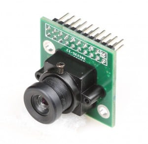
Key specifications active array size: 2592 x 1944 power supply: core: 1.5VDC + 5% (internal regulator) analog: 2.6 ~ 3.0V I/O: 1.7 ~ 3.0V output formats : (8-bit): YUV(422/420) / YCbCr422, RGB565/555/444, CCIR656, 8-bit compression data, 8/10-bit raw RGB data lens size: 1/4...
subtle tree
I'm having a bit of an issue with my code and can't seem to figure out what I'm missing. I have 2 potentiometers I'm using to control 3 LEDs. One pot controls which LED lights up, one pot controls the blink delay, and I have a photoresistor to set the brightness of the LEDs. So far I have the first two objectives done, I can control the LED color and the blink rate, but the brightness isn't changing for some reason. I can print the values to the serial monitor and see that it is indeed reading correctly, but for some reason it isn't applying it to the LED. Can someone possibly give me some assistance?
My code was too long to place here so here is the .ino file
opaque hollow
@subtle tree let me check.
@subtle tree I see what the problem is.
You need to use AnalogWrite instead of DigitalWrite. You will also need to make sure you are using pins with PWM.
 opaque hollow
Are you using a Arduino Uno?
subtle tree
I was indeed using PWM pins but completely forgot I needed analogwrite not digital
I am, yes
opaque hollow
Yep, that would do it.
So yeah, you should just have to change that part of the code and it should work.
subtle tree
hm. Now it is refusing to upload my code to the arduino 
However I believe that would have fixed my issue, so thank you so so much for that
opaque hollow
No problem.
opaque hollow
Good to hear!
subtle tree
I just had the glitch where it has multiple com connections and needed to reset my comp real fast
opaque hollow
Yeah, it hate it when that happens. A quick reboot sure does the trick.
woven fox
Ok. I’ve tried different things. I checked the voltage on the 5v on the wemos and no voltage. Voltage on the 3v. Switched and it and it worked for a bit. I tried changing the pins on the other board and no go there as well. 🤔 Both can run a blink sketch and can be set up as access points. What the french toast.
opaque hollow
So the RGB LED won't light up?
woven fox
Nerp
opaque hollow
Hmm....
woven fox
I have the library is installed for the new pixel library. So that’s running a PWM sketch on the one with the one wire LED. The other one is running a simple Hilow sketch.
opaque hollow
So for some reason there is not 5 volts on the 5V line?
north stream
On which one? The one with the USB connection or the one without?
opaque hollow
⬆
north stream
You're running PWM with the one-wire LED and FastLED with the common cathode RGB LED?
If so, that's backwards...
woven fox
The one that has the USB and is the one running the. Hi low sketch
FastLed on the ws leds
Im sorry 5050
north stream
Yeah, there should be 5V on the Vusb pin on the one connected to USB.
woven fox
Right, but no 5v. What’s interesting is I’ve also seen every example online using the 3v
opaque hollow
Does the Neopixel one work?
woven fox
The new pixel one did work for a short period of time.
For a moment I did think that I burnt out the new pixels. I use the same ones on my multi rotors and I tested it out and they still work
opaque hollow
It should not have burned out, it's possible. But in the photo you have it wired to 3.3V when the strip says 5V, so the LED should not be fried. It may be underpowered.
woven fox
Just kind of has me scratching my head right now
I understand I was going to run into some kind of problems trying to do my first project but I didn’t know it was this easy to run into a problem so soon.
opaque hollow
So, I forget if you have to select a certain board when programming the WEMOs, did you select the right board type?
woven fox
I believe I did I chose the WeMos D-1 lite on Arduino IDE and I’ve also been able to upload to other simple sketches successfully
opaque hollow
So, I don't think the 5V pins is connected to anything since the Wemos D1 Mini Lite D1 only operates at 3.3v.
opaque hollow
Hmm...
woven fox
opaque hollow
Try this in a new sketch:
int redLed = 5;
int greenLed = 7;
int blueLed = 2;

void setup() {
     pinMode(redLed, OUTPUT);
     pinMode(greenLed, OUTPUT);
     pinMode(blueLed, OUTPUT);
}

void loop() {
     digitalWrite(redLed, HIGH);
     digitalWrite(greenLed, HIGH);
     digitalWrite(blueLed, HIGH);
}
For the RGB LED.
If the LED still does not turn on, try changing HIGH to LOW.
woven fox
Ok
opaque hollow
What is the color code of the resistors you are using? Is it: Red Blue Yellow Gold?
north stream
The (common) cathode is connected to ground?
north stream
Yeah, common cathode won't work connected to Vdd
opaque hollow
Put a ; at the end of each line.
pinMode(greenLed, OUTPUT);
Sorry, I forgot to add those at the end.
Nope, I added them.
     pinMode(redLed, OUTPUT);
     pinMode(greenLed, OUTPUT);
     pinMode(blueLed, OUTPUT);
I also want to know the color code of the resistors
opaque hollow
Yeah, they look like they are Red Blue Yellow, which is quite high.
woven fox
Yellow purple red gold
opaque hollow
4.7k
north stream
4.7k, that's reasonable
woven fox
Yes. 4.7
opaque hollow
Hmm... I usually just use 220 ohm. 😆
woven fox
I’ll give anything a go at this point. I think i know a voodoo lady on 82nd.
Might do it for a hotpocket
north stream
Try hooking r
3V to a resistor to one of the LED anoders
woven fox
I’ve performed this very same test kind sir and it works.
north stream
Ok so the Led, resistor, input and power supply are good
opaque hollow
Running a little test with a RGB Common Anode LED with 4.7kΩ resistors on the RGB pins connected to a Adafruit Feather 32u4 RFM69HCW at 3.3v logic, using analogWrite with a value of 0 (Full Brightness for me, Common Anode), the LED is not all that bright. I would not want to stare at it for a couple of seconds. So, the LED should light up for you if your LED is common cathode and you have the common connected to GND (which you do in the picture).
woven fox
Would having the wrong programmer still allow me to upload some sketches and not all?
opaque hollow
I think so. You have the WEMOs D1 Mini Lite board selected in Board right? (It might not be that exact name)
opaque hollow
That is a lot of options.
woven fox
Yes sir. Di mini lite
opaque hollow
I got to go. I will be back soon. I should be back in maybe 10 - 20 minutes.
woven fox
Awesome
opaque hollow
@woven fox Back.
woven fox
Yes sir
opaque hollow
@woven fox did the Sketch that I told you to try, did it work?
woven fox
No it did not. I’m wondering if i should move my project over to an arduino nano
opaque hollow
So, why are you using the Wemos D1 Mini Lite? Was it because you wanted it to be triggered remotely?
opaque hollow
Oh.
woven fox
Yeah. Maybe a bad decision to use these guys. I’ll move over to the Nanos and see if i have luck there
opaque hollow
Try probing with a Multimeter, from the GND pin to one of the digital pins for the LED, Probe D2 and GND.
You should get ~3.3v.
woven fox
Ok. I’ll do that. And see constant 3v?
opaque hollow
Yes. If you are running the sketch that I sent.
woven fox
Ok. I’ll do it.
opaque hollow
Hmm... I may have found something.
opaque hollow
Try this:
int redLed = 14;
int greenLed = 13;
int blueLed = 4;
Ok I’ll do it
opaque hollow
Instead of what you have currently. So instead of:
int redLed = 5;
``` do
```CPP
int redLed = 14;
Uploading
opaque hollow
🤞
opaque hollow
I should have tried typing the pinout in google sooner. 😄
pinout of a Wemos D1 mini
opaque hollow
So, back to your original sketch, just change the pins to what you have now.
opaque hollow
Yeah, I guess. The pin definitions are different from what they are on the board. I have had that issue before. I just wish I would have thought of that sooner.
woven fox
U rock my friend. You have restored my confidence in this new coding adventure of mine. Never stop being a rockstar
So many thanks to u
opaque hollow
Here is a key I snagged from the Arduino Forums.
You are welcome. Let me know if it works.
woven fox
I can’t thank u enough
opaque hollow
As for the NeoPixel, try changing the pin in the code.
opaque hollow
Sweet.
opaque hollow
Okay. No Problem. Have a great night.
woven fox
Like no other now my friend. My first effin project bc of u.
opaque hollow
If you have any more issues or questions, just let us know.
woven fox
Yes sir.
opaque hollow
@woven fox make sure to save that picture of the Board Pinout Key.
@woven fox Here is a better one:
The teal color is the Arduino Pin.
woven fox
Lol i ran back to do just that!
opaque hollow
Hmm... Now I want to play with some RGB. Good thing I bought a 100 pack of 5mm RGB LEDs, well it's not 100 anymore, I used a few.
pine bramble
.oO(.. a bag of candy)
pine bramble
question
could a uno power a portable midi board?
25 keys, velocity sensitive, 8 pads and knobs
pine bramble
Model number and brand?
 sharp turret
@pine bramble The Uno itself isn't a power source. It depends on what IT is powered by and what the device connected to its power pins draws.
woven fox
Where would be a good place to find code for a PIR sensor? I’m trying to get a pir to set off some leds. Is there an example sketch in the arduino ide program?
pine bramble
Model/part number?
 odd fjord
 pine bramble
@pine bramble for the midi controller: Akai Pro MPK Mini MKII
 north stream
To transmit from the Uno to the Pi (5V to 3.3V), a voltage divider is sufficient. To send data back from the Pi to the Uno (3.3V to 5V), it might work without a level shifter.
proven mauve
how sensitive are 328P's to soldering irons?
north stream
The DIP packaged ones are fairly robust, the SMT ones somewhat less so, presumably.
proven mauve
I think I fried one soldering it =/
embedded it into a project... then nothing worked. ook it apart part by part. Ended up with nothing hooked up to it except a clock... took that off, hooked it up to a programmer with a known working clock, no dice
I might be able to take it off the pcb when my new flux comes tomorrow, then I can test it more
north stream
It is possible, of course. Also, if you don't have a grounded iron you could have issues with static or other voltage damaging it.
mild elk
I've been tinkering a bit with that rotary encoder and I still can't get it to work - maybe anyone has some more suggestions? And if not I guess I'll stick with good old buttons
Although my Arduino doesn't even register buttons properly
Well, I replaced ATmega328 in my uno and it does the same, so Arduino is probably perfectly fine
This is getting increasingly annoying
rocky igloo
@mild elk I'm sorry that I haven't followed all that closely so I don't know what you've tried, but when I get stuck on something I like to go back to the most basic test. For example: https://playground.arduino.cc/Main/RotaryEncoders/#Example1
If that doesn't work, your code isn't the problem. Then it could be your wiring, the MCU pins, or the encoder.
potent ferry
Hi Guys. Is there anyone that could share a line of arduino coding for controlling 1 servomotor's rotation by the frequency of the movement of 2 accelerometers ? Meaning, lower frequency of alternating movement of 2 accelerimeters => rotation of 1 servomotor of a small angle ; higher frequency of alternating movement of 2 accelerometers => rotation of the same servomotor of a bigger angle ?
Thanks
north stream
@potent ferry Why two accelerometers? What kind of accelerometers? What kind of acceleration?
potent ferry
I wear 1 accelerometer per foot to control the rotation of 1 servomotor. I am using for now the Gy-521 MPU-6050 , but i also have these 2 accelerometers
https://www.analog.com/media/en/technical-documentation/data-sheets/ADXL345.pdf

As you can see, i am moving 1 accelerometer at a time, walking. The acceleration would be both vertical acceleration (if walking in place) and lateral acceleration (when walking accross the room)
Would you please be able to guide me to what type of function could be used and code lines, for controlling the rotation of 1 servomotor with 2 accelerometers that are moving up and down 1 at a time, by considerimg the frequency of their movements ?
Tx
pine bramble
function and code lines? No nononon... It works the other way around. What, in human, do you want it to do?
north stream
I'd probably have something like "note the timestamp when the acceleration goes through zero in a positive direction", "note the timestamp when the acceleration goes through zero in a negative direction", subtract the timestamps to get the elapsed time, then if it's small (more frequent motions) set the servo to a bigger angle, if it's large (less frequent motions), set the servo to a larger angle. Probably need to fold in logic to look for reasonable sized peaks in-between, to avoid spurious crossings, and to cross-check the two accelerometers for alternate motion.
pine bramble
Sounds like you'll need a good mapping function..
I got to stop hitting return.
Here's the .h
https://github.com/leftCoast/Arduino/blob/master/libraries/LC_baseTools/mapper.h
Here's the .cpp
https://github.com/leftCoast/Arduino/blob/master/libraries/LC_baseTools/mapper.cpp
Takes 4 numbers to setup. In your case it would be. mapper servoMapper(MinFreq,MaxFreq,MinServo,MaxServo); Then you just use it by servoVal = servoMapper->Map(FreqValue);
Gives back a float, you can round it to an int.
potent ferry
Way above my basic knoledge of arduino :(
Thank you so much for the replies. I am lost. Too complicated for me
lost notch
So what does it mean again when an HC05 Bluetooth Module blinks slowly twice every 8 seconds?
 minor sinew
trying to understand the demo code that came with the breakout board i got: is this code just for writing to the serial monitor?
i'm trying to send the output of my thermocouple to my 4d sys screen
which operates off of genie.WriteObject(GENIE_OBJ_GAUGE, 0x00, ___);
i think i also have a conflict with my serial ports, and i'm working on learning that 😬
north stream
You might need something like ```c
genie.println(thermocouple.readCelsius());
I don't know offhand what the 4D Sys screen supports, however.
minor sinew
i'll write that down and try that, still gotta figure this serial issue out lol
whole thing was going fubar yesterday. can't wait till i try to run 8-12 of these things.
north stream
Looking more closely at what you wrote, perhaps ```c
genie.WriteObject(GENIE_OBJ_GAUGE, 0x00, thermocouple.readCelsius());
And to answer your other question, yes, the Serial.print() type statements write to a serial monitor, or at least they attempt to, depending on your board, how it's hooked up, etc.
minor sinew
the 4d screen already graphically renders stuff, you just send it a number value from 0-100 (in the case for the value range that object in particular has) and it'll do the rest
and if i'm running 8-12 of these boards i shouldn't need more than on serial port, from my understand?
north stream
8-12 of which? The thermocouple boards, the CPU boards, the displays, or some combination?
minor sinew
thermocouple boards
going into one arduino host (a mega 2560 currently that i'm working on right now), which translate it to code for my screen
i'm just trying to understand if there's a hard limit to how many of these thermocouple boards i can read (the max31855)
north stream
They're basically an SPI interface, so they can all share the CLK and DO/MISO pins, and each board will need its own CS pin. With a Mega, you should have plenty of I/O pins to do this.
minor sinew
yeah i got plenty lol
i think i'll need to order another board here soon to experiment with
 spare otter
Hi! I've been in this group for months. but this is my first time interacting around. So, I am learning how to use an Arduino UNO board, as well as learning how to utilize the IDE. I hope I ask this on the right place, is there any guide, tutorial or resource you may recommend to effectively learning arduino from its core, and not just following a set of instructions blindly? I am technically a 'noob' and only know the very very basics (hello world kinda). I know Python, basic Java, and have some slight notion of C
pine bramble
@mild elk I'm working on releasing my rotary encoder code for Arduino IDE.
The original project had GPS, LED, RGB LED and a piezo buzzer (sending messages in morse code) and a large character LCD.
The initial port will just be for the rotary encoder and an LED indicator.
mild elk
I'm interested
I wish to be pinged when it's released
pine bramble
My github is user wa1tnr .. easy to find there. ;)
mild elk
Alright, thanks
pine bramble
I just have to sort out any license snafus from the upstream source(s) as the first time I did this I didn't pay attention to licensing.
mild elk
Well, when I was releasing my DS3231 library I was really surprised when it asked me which license I want to use, I didn't think about it earlier
Although I'm not sure if it makes any sense to keep that repo up since no one seems interested and I can deal with DS3231 without any libraries
mild elk
@spare otter I always prefer learning by experience, so just like now I got a rotary encoder and I'm trying to do something with it. Before I got started with Arduino, I also didn't know anything. Just a little C++. And if you ever have trouble with something, you can ask around and hopefully get your problem solved
north stream
Unfortunately, I come from an assembler background, so my route to learning Arduino is probably not particularly useful, nor do I know of any good beginner tutorials (although I assume they're out there). You didn't ask in the wrong place, but not a lot of people may be around at any given time, and sometimes (as now), the people who are around may not have much to offer. I don't consider it helpful to speak up when I don't have something constructive to add, so I generally don't.
 novel hinge
I have an annoying problem, this loop function only runs once and takes far too long to run, on the order of seconds when I should be able to get 60hz full frame dumps.
I'm not sure why it's so slow
pine bramble
@novel hinge bracket every registerRead() with Serial.println("test"); and see if it's fast or slow.
also, initialize every variable.
north stream
I'm guessing it's getting delayed by the "hold" logic, so may be getting slowed down waiting for the peripheral to be ready.
novel hinge
Hrm, will give these a shot when I get back to the computer tonight
I think it could be the hold logic but I already did a logic cap of the SPI bus, and it's definitely dumping at the correct rate
north kelp
@spare otter I'd suggest poking around in the Adafruit Learning System for projects that look interesting. There's also this series of lessons for the basics:
https://learn.adafruit.com/series/learn-arduino
minor sinew
so i got my screen to write the code, and my serial input issue resolved @north stream
but my c is being ripped from the temp ontop of the board, rather than my thermocouple that was attached, any ideas as to what's messed up here?
{
  inttemp = thermocouple.readInternal();
  Serial.print("Internal Temp - ");
  Serial.println(inttemp);

  c = thermocouple.readCelsius();
  if (isnan(c)) {
    Serial.println("Something wrong with thermocouple!");
  } else {
    Serial.print("C = ");
    Serial.println(c);
  }
  genie.WriteObject(GENIE_OBJ_GAUGE, 0x00, c );
  genie.WriteObject(GENIE_OBJ_CUSTOM_DIGITS, 0x00, c );
  delay(1000);
}```It looks right to me: do the internal temperature and celsius temperature vary?
north stream
No change by heating/cooling the thermocouple?
novel hinge
sounds like you might have polarity of the thermocouple leads reversed
*if the chip is polarized
minor sinew
chip is, but i know they aren't messed up
both of those numbers on the monitor change when i put my finger on the chip
so it's already verified it's not reading the tc
minor sinew
before when my tc was reading properly if it's temperature reading changed, the chip temperature wouldn't change
it's weird because the C = are rounded
north stream
I'm looking at the source code for the library, and it's a little odd.
As far as I can tell both readInternal() and readCelsius() read the junction (not chip) temperature.
However, they do different scaling/rounding calculations for some reason.
Erf, maybe not. I'm looking at the chip's data sheet, and it's a little odd. It's not a register-based device so reading different numbers of bits from it give different functions. 🤔
minor sinew
just tried
{
  Serial.print("Internal Temp - ");
  Serial.println(thermocouple.readInternal());

  double c= thermocouple.readCelsius();
  if (isnan(c)) {
    Serial.println("Something wrong with thermocouple!");
  } else {
    Serial.print("C = ");
    Serial.println(c);
  }
  genie.WriteObject(GENIE_OBJ_GAUGE, 0x00, c);
  genie.WriteObject(GENIE_OBJ_CUSTOM_DIGITS, 0x00, c);
  delay(1000);
}```instead and that did nothing
north stream
Did nothing or no change?
north stream
I don't know. My best guess is your TC is broken or hooked up wrong, but you said you know it isn't messed up.
minor sinew
i just double checked everything
the whole thing is
#include<SPI.h>
#include<Adafruit_MAX31855.h>

#define MAXDO  3
#define MAXCS  4
#define MAXCLK 5

double inttemp;
double c;
double t = 10;

Adafruit_MAX31855 thermocouple(MAXCLK, MAXCS, MAXDO);
Genie genie;

void setup()
{
  Serial.begin(9600);
  while (!Serial) delay(1);
  Serial1.begin(9600);
  while (!Serial1) delay(1);
  genie.Begin(Serial1);
  Serial.println("MAX31855 test");
  delay(2500);
}

void loop()
{
  inttemp = thermocouple.readInternal();
  Serial.print("Internal Temp - ");
  Serial.println(inttemp);

  c = thermocouple.readCelsius();
  if (isnan(c)) {
    Serial.println("Something wrong with thermocouple!");
  } else {
    Serial.print("C = ");
    Serial.println(c);
  }
  genie.WriteObject(GENIE_OBJ_GAUGE, 0x00, c );
  genie.WriteObject(GENIE_OBJ_CUSTOM_DIGITS, 0x00, c );
  delay(1000);
}```Looks right as far as I can tell. Make sure there's a solid connection to the thermocouple wires, they're an odd composition and even a small amount of resistance can cause issues with such small signals.
minor sinew
just did that
i hate bots
anyway
something might be f'd up with this tc
i'll try a different once
minor sinew
yeah i did that and now the tc is reading it seems
but it's going lower when i touch it
which doesn't make much sense
if i reverse the polarity weird out big time and goes past where it should be by a lot
pine bramble
Would be more readable (by a lot) if you:
```cpp
at the beginning and
```
at the end of that. ;)
pine bramble
cpp is c++ basically (or maybe C preprocessor)
Discord markup, basically. You can name the language on the first line.
minor sinew
ah
pine bramble
When it's correct it'll be syntax highlighted in colors.
Your brain starts to see it differently and can skip over stuff it doesn't want to know right now.
minor sinew
i think i figured out was what wrong. cheap chinese goushi didn't mark the polarities right it seems.
pine bramble
Hey, plus now you know it's durable if you do reverse it. ;)
pine bramble
I used TMP36 but my accuracy requirement was in chunks of 3 degrees F as good enough.
Still it happens to read room temperature literally, which is nice.
(if the numbers that come out of it .. in milivolts .. are near 725 (72.5 * 10) (0.725 volts) then it's 72.5 degrees F currently).
That doesn't map very far from 72 F but still it's a nice mnemonic while working on the prototype.
Temp °C = 100*(reading in V) - 50
So,
59 F = 15 C 15 = 100*(.65) - 50
68 F = 20 C 20 = 100*(.70) - 50
72 F = 22.22 C 22.22 = 100*(.72) - 50 = 72 - 50 = 22
77 F = 25 C 25 = 100*(.75) - 50
86 F = 30 C 30 = 100*(.80) - 50
 hidden finch
Are there any basic troubleshooting steps I should go through with my microSD card reader if it isn't working, and I know it is wired correctly?
north stream
What kind of "reader"? Just a socket, or does it have a level shifter or USB interface or something? When you say "wired correctly", it sounds like a breadboard, but "reader" sounds like a USB widget?
hidden finch
The microSD card breakout board 254
I modified the chipSelect variable in cardinfo to be 10 to be clear
north stream
How are you powering it?
hidden finch
Off of the 5v connection on my Nano
north stream
How far does the sketch get?
hidden finch
it fails at initializing
Initializing SD card...initialization failed. Things to check:
* is a card inserted?
* is your wiring correct?
* did you change the chipSelect pin to match your shield or module?
Hmm, something pretty basic then. I think the hardware SPI pins on the Nano are the same as the Uno.
Hmm, maybe call card.errorCode() and card.errorData() for clues?
north stream
Hmm, 1 is SD_CARD_ERROR_CMD0 https://github.com/arduino-libraries/SD/blob/master/src/utility/Sd2Card.h#L120
That's the very first thing it attempts to do, and the card doesn't seem to answer.
north stream
Could be. At this point, I'd either try software SPI or reach for an oscilloscope.
Or grab another SPI peripheral and see if it works.
rocky igloo
This is where I swap MISO and MOSI. (Only half 😁)
north stream
I like the concept of MISO and MOSI (easier to figure out than "transmit" and "receive" and trying to figure out the point of view)
But SPI is still a slightly goofy protocol where both the master and slave both send and receive 1 bit per clock.
rocky igloo
I agree that it's clearer than rx and tx, unless we over-think it and forget that they don't have to cross.
But it's more me being "slightly goofy" and looking at it a dozen times being totally sure that it's hooked up right, but it isn't.
Anyway... @hidden finch is the activity LED on the breakout lighting? All that tells you is that the SPI clock is toggling, but it's something.
north stream
Oh, good catch, I forgot that breakout has an LED
rocky igloo
Not a heck of a lot going on there. It's a CD4050 hex buffer and a voltage regulator.
hidden finch
no it doesn't light up at all
rocky igloo
OK, lemme think...
Nano is like Arduino Uno, right? So hardware SPI is 11-MOSI, 12-MISO, 13-SCK. Is that what you've got connected? I'm thinking that the example Blink sketch which turns digital pin 13 on and off should also turn the breakout led on and off, since they're on the same pin.
I would try that. If the led on the Nano blinks but the one on the breakout doesn't, it's connections or no power or a bad voltage regulator.
 low thistle
Idk if this is the right place to ask but, I'm trying to hack a IKEA FANTAST Thermomether: https://www.ikea.com/se/sv/p/fantast-stektermometer-timer-digital-svart-20103016/
I want to tap into the temperature readings with an arduino. I could probably monitor the display pins and figure out which pins correspond to which lines on the display, but there must be an easier way of reading the temperature. Does anyone know what kind of temperature probe this kind of thermometer usually uses?
Edit: Figured out the probe is just a NTC thermistor, so it'll be easy enuf.

IKEA
IKEA - FANTAST, Stektermometer/timer, digital svart, Magnet på baksidan - kan fästas på t.ex. kylskåp. Batterier säljes separat; 1 st LR03 AAA 1,5V behövs. Mäter temperaturer upp till 250°C/480°F. Sladden är värmetålig upp till 250°C/480°F.
karmic stream
how would I simulate a software interrupt on PORTD2(Pin D2) on an ATmega328p if the "hardware" interrupt already works?
When the INT0 bit is set (one) and the I-bit in the Status Register (SREG) is set (one), the external pin interrupt is enabled. The Interrupt Sense Control0 bits 1/0 (ISC01 and ISC00) in the External Interrupt Control Register A (EICRA) define whether the external interrupt is activated on rising and/or falling edge of the INT0 pin or level sensed. Activity on the pin will cause an interrupt request even if INT0 is configured as an output. The corresponding interrupt of External Interrupt Request 0 is executed from the INT0 Interrupt Vector.```
How do I enforce this activity from software?Maybe just call the ISR function.
Or write a parallel one that doesn't talk to the hardware.
maybe gdb
Someone familiar with debugger technology might be of service.
karmic stream
hm. I wonder how much of a difference it would make to simply call the function. kinda cheaty..
proven mauve
Hey, am I able to take a standard atmega32u4 and turn it into a circuitPython device? I don't think I have any other chips with onboard usb
north stream
No, the AVR chips don't have the capability to run CircuitPython. That's generally the realm of 32-bit CPUs.
north stream
There are some surprisingly affordable Python-capable boards available. The Trinket is about the cheapest, but I have a real fondness for the ItsyBitsy M4 Express, which is much more capable and still not expensive.
 cosmic steppe
anybody know how to calculate temperature with a calibration curve of voltage and temperature?
north stream
Not much to it, really: https://www.ametherm.com/thermistor/ntc-thermistor-calculating-the-temperature-coefficient-of-a-thermistor Look up "Steinhart equation" for all the gory details.
cosmic steppe
thanks
 rough torrent
hey there, I am using the arduino ide to program the pygamer, but I always get exit status 1 error compiling. i can upload the blink sketch fine and .uf2 works but the arcada_pygamer_test doesn't work.
before it wasn't working but i removed the device from device manager and it worked
i've also tried reinstalling all the libraries
here are my error messages
circuitpython works though when i install the uf2
pine bramble
@rough torrent The error messages were a good idea, but seeing the source code that generates them would also be useful, here. ;)
Shorter recap of the error:
https://termbin.com/4o8dv
okay you're on 1.5.1 not 1.5.7 on the
.arduino15/packages/adafruit/hardware/samd/1.5.7/variants/pygamer_m4/variant.h
path ..
It's quite important to upgrade the Adafruit related SAMD support (the BSP) and exit Arduino IDE.
This, for example, in 1.5.3 (I Think; not sure):
https://github.com/adafruit/ArduinoCore-samd/commit/ff2cb608a9d2506b3279dd287628c9962dbba249#diff-cbd2aea5bc0eb917dc72a00c363b2ccf
aka
https://preview.tinyurl.com/long-nis-uri-cfbda42 same thing made tiny
@rough torrent I'm thinking that upgrade might be the only problem here.
rough torrent
@pine bramble , I used the example pygamer arcada test in full board tests
 paper ledge
Alright i'm at a loss
attempting to connect my adafruit huzzah esp8266 to an arduino uno with serial communication
I do have a level shifter to handle the different logic levels
but communication is not being established.
north stream
Which end is not receiving data?
paper ledge
@north stream Just now seeing your message. Well turns out it actually WAS communicating, the baud rates were the same on both sides but at 115200 baud rates the output was getting corrupted
I bumped down to 19200 and everything is working like a charm now
Just one of those times that I needed to ask for help before my light bulb finally turned on 😉
north stream
That's known as "rubber duck debugging": sometimes just the act of sharing your problem is what gets the brain going. One person decided instead of bothering their co-workers, they'd just explain their problem to a rubber duck, and it worked! https://rubberduckdebugging.com/ However, we're happy to be the rubber ducks here, because reading about people solving problems is instructive, and it lets us know that we're not the only people who don't get it right the first time.
 undone oracle
Hey i have a question. I wrote a program that rotates a servo(using arduino nano) every 15 minutes. For some reason once it hits the specified angle, it stays there for a minute or 2 then returns back to the original position. Do i need to put servo.detach in the void loop?
I do not want the servo to return to its original position. I need it to remian where i want it to be until the next for loop.
 crude magnet
@undone oracle can you share your code on pastebin or something so we can see what you're doing?
undone oracle
@crude magnet sure just give me a few minutes
crude magnet
general advice: you shouldn't need to do servo.detach() in loop()
and if your motor is moving before you want it to, it's because somethin in your loop() is telling it to earlier than you think 😸
seeing your code will help us figure out where that's happening
crude magnet
@undone oracle are you using the RTC thing because you need things to happen at a specific time, or do you just need things to happen at a certain interval?
crude magnet
so you will be setting this up to get the correct date and time when it turns on?
undone oracle
Then it reverts back to the original position in the void setup
I already set up the rtc
It has the correct date and time
crude magnet
ok
undone oracle
I just dont know why it reverts back to the original position after every for loop
north stream
You could simplify your code by making the computer do the math: ```c
//--------------------------------9AM---------------------------//
if (myRTC.hours == 9) {
if ((myRTC.minutes % 15) == 0) {
switch (myRTC.seconds) {
case 1:
servox.write(180 - (27 + myRTC.minutes / 5));
break;
case 10:
servoy.write(24 + 2 * minutes / 15);
break;
}
}
}
Oh ive wanted to do that but couldnt figure it out, thanks @north stream
The break statement is interesting
Reminds me of pass in python
pine bramble
break just stops it from dropping through
north stream
That just tells it to jump out of the switch statement: otherwise it "falls through" to the next case statement.
It's closer to continue in Python
undone oracle
So in my code, do i put a break in each for loop?
north stream
You can put break statements in for loops, but I don't see any in your code.
pine bramble
🤔
north stream
I'd probably make the minutes % 15 the outermost if, and fold the hours into the position calculations.
pine bramble
cant you label loops in cpp?
crude magnet
@tight gyro the loop() function isn't a loop in the traditional sense
it's a method that gets called repeatedly by the arduino stuff
for and while loops are features of the language
control statements
break affects control statements
pine bramble
yeah, and loops are control statements
crude magnet
for (int i = 0; i < 10;  i++)
{
    // Do something

    if (//some condition)
    {
        break;
    }
}
the above code snippet is the kind of loop that @north stream was talking about
in this snippet, the loop will run the code inside the {} 10 times
each time it runs through, the if statement will check some condition
if it's true, the break will exit the for loop early
meaning that it won't run any further iterations
even if you're only on the 5th time through
undone oracle
Ok but my question is, why does it run the void setup even after it enters the void loop?
crude magnet
what makes you think it's running setup()?
undone oracle
Bc when the void loop runs, after a minute it reverts back to the position in the void set up
crude magnet
have you tried putting a Serial.println(...) in your setup() method and checking if that appears on the console?
undone oracle
I have a serial.print to read the rtc
crude magnet
print statements are very useful for debugging 😸
@tight gyro that's in your loop() function
add a print statement to your setup() so you can verify that it's actually running setup() again after running the loop()
undone oracle
Im not rlly sure how to do that lol
crude magnet
just add the line Serial.println("Setup is running!"); anywhere in the setup() method
then after you upload the code, you can open the serial monitor in the Arduino IDE
you'll find it in the Tools menu
or you can just type Ctrl-Shift-m
undone oracle
Ok i could do that
But if the setup loop is indeed running, what could i do to fix that?
Adding breaks or something like that?
crude magnet
let's make sure it's doing what you think before we try to debug it 😸
when the Serial Monitor opens, you'll see a dropdown at the bottom right of the window that says XXXX baud
you'll have to select 9600 baud in that dropdown, since that's the speed you chose on the arduino
undone oracle
The reason why i believe the setup is running is bc after the for loop runs, the servo goes back to servox.write(180) and servoy.write(0)
crude magnet
otherwise, you'll just get gobbledygook 😸
undone oracle
Which is only specified in the setup
But ill try adding the setup is running now line
crude magnet
oh
when i said anywhere in setup() earlier, I meant anywhere after Serial.begin(9600);
😸
crude magnet
keep an eye on the serial monitor and see if it prints your new message when the motor moves back
 ⏰
crude magnet
⏰
crude magnet
the loop is actually running every second
which is why you get the "Current Date..." on the serial monitor repeatedly
your code just doesn't do anything unless it's a certain time. 😸
undone oracle
Yea i meant the next time the servos move
It orientates a solar panel in the direction of sunlight using a timer and servo motors. I entered the azimuth and elevation angles for the x axis servo and y axis servo
Here is a picture of what happenes right after it hits one of those if loops
The panel is orienated in the correct position, but after a minute, it goes back to pointing at the ground :(
crude magnet
neat project! 😸
so, when it points back at the ground, do you see that message in the serial monitor?
undone oracle
We need to wait 1 more min
I set it up so it moves 4 times per hour (every 15 mins)
It didnt go back quite yet...
Maybe it goes back only when both the x and y axis move
Bc for 12pm (my time now) i have it so only the x axis moves but not the y axis
crude magnet
it's possible that's the case
if it really is running setup() again
that means the arduino reset itself, generally
undone oracle
Guess we have to have another half hour to see what happenes
Yes that is what it would mean
crude magnet
if you have the servos hooked up directly to the arduino, they may be drawing too much current when both moving to keep the arduino powered
this would cause a brown-out reset
what's your circuit look like?
undone oracle
The circuit is really simple
No resistors or capacitors. Just
1 arduino nano
2 servo motors
1 ds1302 rtc
1 5v power supply module
crude magnet
so, you can test if it's browning out pretty easily
undone oracle
So if i understand this properly, the arduino wants to revert the servos to the original position bc they are drawing too much current? This is a bigger problem than i thought.😳
crude magnet
comment out all the code in your loop() and replace it with something simpler
some code that you think will cause the brown out
i.e. moving both servos at the same time
undone oracle
What does brown out mean?
And yes, i did have code that moved both servos at the same time. It worked but i prefer if the movements were 10 seconds apart so it doesnt jerk back and forth
crude magnet
it basically means that the ic isn't getting enough power to keep running
so it ends up resetting
meaning it will run your entire program from the start again
undone oracle
Hmm.. im using a 5v power supply tho
crude magnet
which is why you would hit setup() twice
@tight gyro when the motors are running, they draw a decent amount of power
this means less power is available for the arduino
undone oracle
Ok that makes sense
crude magnet
i don't know for sure if this is your problem. this is just one possible explanation 😸
undone oracle
We need to wait 15 more mins to find out.
crude magnet
reproducing it with some simpler code in loop() is a good way to find out if that's happening
undone oracle
In 15 mins both servos are scheduled to move
crude magnet
@tight gyro well, you could just upload new code that moves both servos after a few seconds. 😸
undone oracle
Thing is, i tested that so many times. And it seemed to have worked fine
crude magnet
a good method in debugging code is to reduce your code down to the simplest program that reproduces the problem you're seeing
undone oracle
So from the looks of things, im gonna have to add capactiors and stuff like that? Oh no, i already soldered my pcp
crude magnet
verify the problem before you come up with solutions 😸
undone oracle
True, ive been up for about 21 hours working on this, i really hope i can fix my problem
crude magnet
that also doesn't help make debugging any easier :-P
how much current is your power supply rated for?
undone oracle
Hm, idk. It a Rex Qualis power supply module. It does look extremely cheap tho
undone oracle
Wow my professor mightve been right, i may need to get driver cuircits for the servos😱
crude magnet
well, yeah... :-P
undone oracle
Right now, the arduino nano is plugged into my laptop. When it away from my laptop i use a portable phone charger to power it
And plus the nano has to be plugged in to the laptop to read the serial monitor
crude magnet
so, i think in either case, you're getting 500mA out of your power source
undone oracle
Is that good or bad
undone oracle
SG-90
crude magnet
are you trying to make this rotate all the way around, perchance?
undone oracle
The x axis goes from 0 to 141
The y axis goes from 0 to 35
Ok this is interesting.. it seems that when i power the arduino with my laptop, it works fine. But when i use the power supply module it starts acting crazy
crude magnet
oh!
there's a problem that a lot of phone charger battery things have for this kind of thing
undone oracle
Maybe i should power the arduino with my portable battery charger, and not through the power supply module
crude magnet
they turn off
undone oracle
Oh do they?
crude magnet
yes
undone oracle
I have a really good battery pack tho. Anker
crude magnet
if the circuit isn't drawing much power, it shuts off the charging circuit automatically
in this case, really good would make it more likely to have this feature 😸
basically, it shuts the charging circuit off when the battery is fully charged or not plugged in
after some amount of time
(possibly 2 minutes :-P)
undone oracle
Huh, idk if my battery pack has that feature
crude magnet
it most likely does
especially if this problem only happens when you're powered by the battery
undone oracle
Ok so im gonna try powering it with a wall outlet and an extension chord
And if i want to go portable, im gonna have to use a lipo battery with a 5v booster circuit
And a lipo battery charging IC ofcourse
crude magnet
or, you can just use one of these: https://www.adafruit.com/product/3784

Here's another addition to our growing family of AA battery holders. A holder for four (4) AA batteries! It's got an 8" long power cable with a 2.1mm DC jack ...
undone oracle
Holy crap i need that
crude magnet
lol
undone oracle
Thanks for helping me figure out the issue, even though it took hours😂 @crude magnet
I really hope this is the true solution
Im very bad at power calculations, just power supplying in general
Im just glad my 300 line code is fine lol
Thanks again bro @crude magnet ill keep u updated on my project👍
undone oracle
Yea its my design project. I need to complete it to graduate! Lol
 wet crystal
Does the ESP32 Wroover module accept 5v logic?
wet crystal
Kk
Does the FTDI chip on a nano for example cares if there is another chip than the atmega168 on rx and tx?
Shouldn´t bother right?
mild elk
@wet crystal you have to ground the reset pin on that Arduino to use it as a USB to serial converter. I used to do that with an UNO and ESP 8266
north stream
There's a 1k resistor between the FTDI chip and the AVR, so the AVR can talk to something else without fighting with the FTDI chip.
mild elk
Although I don't think any Arduino uses FTDI chip anymore
Uno has ATmega16u2 and Nano has I think CH340
And some boards like Leonardo, Micro or new Nano series have no USB to serial chip
Nah, I was wrong, the old Nano indeed has an FTDI chip
pine bramble
I'm having trouble using Serial1 on my ItsyBitsy M4. Serial(115200) is the USB connection, Serial1(9600) to a GPS module. It worked fine on an Uno with SoftwareSerial but i'm getting garbage from Serial1 (rx = pin 0). No logic analyzer here now. Any ideas?
rough torrent
@pine bramble , I tried updating arduino samd and adafruit samd but it still doesn't work
here are my new errors
and i am using the arcada_pygamer_test
pine bramble
I'll take a look @rough torrent
rough torrent
thks a lot
pine bramble
Arduino\libraries\Adafruit_Unified_Sensor/Adafruit_Sensor.h:146:37: warning: unused parameter 'enabled' [-Wunused-parameter]
Either that means something, or there's another error that causes the compiler to lose track (and then this error isn't real).
You need to compile entirely unmodified code (ideally) to test when you aren't sure what's going on.
Once the distributed example code compiles successfully, then you can do modifications.
The more mods you do without testing against the C compiler, the more errors the compiler will throw. ;)
(more or less)
rough torrent
i'm using the arcada_pygamer_test in the examples column
pine bramble
Did you update all your libraries? The unified sensor lib may be out of date, for example.
rough torrent
yes
to my knowledge
i selected latest version and installed on every required library
pine bramble
Maybe compile something simpler that will definitely run correctly, to get some experience.
rough torrent
blink runs
pine bramble
Yeah but you're still asking, so the experience can be valuable.
pine bramble
Build something up from scratch until it breaks, and fix it.
Every fix that you do on your own will potentially give you an 'aha' moment.
And those are great.
All of a sudden you'll decide to tackle the one that gave you trouble, and you'll see something you hadn't noticed before. ;)
rough torrent
that s me in a nutshell
pine bramble
Link to the example code here in case someone comes along who already has an idea what's going on (I don't).
pine bramble
rough torrent
even this isn't working:
#include <Adafruit_Arcada.h>

Adafruit_Arcada arcada;

void setup() {
  // put your setup code here, to run once:

}

void loop() {
  // put your main code here, to run repeatedly:

}
nor this:
#include <Adafruit_FreeTouch.h>
#include <adafruit_ptc.h>
#include <pinmux.h>
#include <samd21_ptc_component.h>
That was a good idea .. the first block you cited, there. Empty setup and loop. ;)
Try quoting the include
rough torrent
this is what I have so far:
WORK:

#include <Adafruit_PixelDust.h>

#include <Adafruit_ImageReader.h>

DON'T WORK:

#include <Adafruit_Arcada.h>

#include <Adafruit_FreeTouch.h>
#include <adafruit_ptc.h>
#include <pinmux.h>
#include <samd21_ptc_component.h>
#include <"Adafruit_foo"> or #include "Adafruit_foo"
rough torrent
what do you mean by quoting the include? defining an object like Adafruit_Arcada arcada;?