#help-with-arduino
1 messages · Page 41 of 1
 jade lichen
Here's my code:
playState = digitalRead(PLAY);
// compare the buttonState to its previous state
if (playState != lastPlayState) {
// if the state has changed, increment the counter
if (playState == 0) {
TrinketHidCombo.pressMultimediaKey(MMKEY_PLAYPAUSE);
} else {
// if the current state is LOW then the button went from on to off:
}
// Delay a little bit to avoid bouncing
delay(5);
}
lastPlayState = playState;
I've increased the delay() and that seems to reduce (but not eliminate) the erroneous presses, but it's a little excessive - I'm up to delay(200) now.
 north stream
I usually use a debounce library (like Bounce2) to deal with that for me.
However, you're right, bouncing should be done within 5ms or so.
Do you have a pull-up resistor?
 pearl vale
I'm doing some hacking on the M$Eyes code but an having troubles getting to deploy to the hardware. From the Arduino IDE it works maybe 1 of 10 attempts. Is there a way to have the IDE generate a UF2?
jade lichen
@north stream Not in my circuit, INPUT_PULLUP to use the internal ones
north stream
Yeah, that should work, which leaves the question of why it's still producing spurious input after 200ms.
jade lichen
200ms is pretty clean and useable. every now and again I've seen multiple inputs, and I'm wondering what havoc it's wreaking on the USB polling, which is /supposed/ to be done ever 10ms
 tough estuary
Is the bootloader on the Feather32u4 the standard arduino bootloader?
 neon trench
Hi! Just got one of the cool CircuitPlayground Express Gizmos. I've noticed that the Uncanny Eye project mentions the CPX and the lsat commit mentions Gizmo support. I've bolted on my Gizmo, loaded the sketch in Arduino, selected the CircuitPlayground express board, and it looks like the sketch is loading up, but I just see a backlight underneath a black screen - no eye movement. I don't seem to see any guides on the CPX Gizmo. Any help on this is most appreciated. Thanks! John https://github.com/adafruit/Uncanny_Eyes/blob/master/uncannyEyes/config.h

GitHub
Contribute to adafruit/Uncanny_Eyes development by creating an account on GitHub.
 narrow thorn
Is there any special trick to uploading to the ESP32 Huzzah ?
I have the usb driver loaded..
esptool.py v2.6
Serial port COM7
Connecting....
Chip is ESP32D0WDQ6 (revision 1)
Features: WiFi, BT, Dual Core, 240MHz, VRef calibration in efuse, Coding Scheme None
MAC: 80:7d:3a:f0:58:ec
Uploading stub...
Running stub...
Stub running...
Configuring flash size...
Warning: Could not auto-detect Flash size (FlashID=0xffffff, SizeID=0xff), defaulting to 4MB
Compressed 8192 bytes to 47...
A fatal error occurred: Timed out waiting for packet content
A fatal error occurred: Timed out waiting for packet content
Arduino 1.8.10 with esp32 stable branch 1.0.3.. Adafruit ESP32 Huzzah selected.
I get the same error when I try and load one of the example sketches for ble
weird.. now it is working
 river osprey
I'm trying to code something on an old CircuitPlayground classic I have, and the only board available I see is "Circuit Playground Express" and when I select that, it fails to be able to upload - is there a better device for me to us, or is something else going on?
the sketch compiles (both blink, and the one i actually want) it's upload that fails
I only have 1 device showing up in "ports" and it's listed as Citcuit Playground, the error I get is: No device found on COM24
An error occurred while uploading the sketch
OK - turns out there is a "circuit playground" device later on in the list that allowed it to work
jade lichen
Have you selected Circuit Playground from the boards manager before looking for it in ports?
 somber geode
Hello, I am not certain what 'Programmer' I need to have selected to program a Feather M0 (not the express one) in the ardiuno IDE.
 honest nimbus
It looks like it may be ignored, since the M0 has native USB. But the screenshots in the learn.adafruit tutorial show both AVRISP mkII and USBtinyISP selected, so either should work.

 rocky igloo
I had one of those boards right next to me so I plugged it in and tried 4 different programmer choices, and it worked each time. I was a little surprised because some of them seem like reasonable hardware that someone might really use, but as you say it didn't make a difference which one I chose.
somber geode
Thank you so much.
honest nimbus
I'm trying to work around the old-version Trinket Arduino IDE bug by programming it as a bare ATTiny85. Problem is, I keep getting failures from avrdude such as
avrdude: Expected signature for ATtiny85 is 1E 93 0B
Double check chip, or use -F to override this check.```The device signature keeps changing. Sometimes it's the same weird value, other times it's 0x000000 or just random garbage.
I'm pretty sure the connections are good??? So is this a bricked chip?
Solved it. Oy. Silly issue but a real brain-buster
The Arduino UNO I was using was getting power from a source that sags to about 4.7V. The Trinket was getting power from a different source that sits nicely at 5.2V.
I powered the Trinket from the Uno's 5V out header and re-burned the bootloader and it works just fine
Correction: It worked once, and now I get a bunch of avrdude: verifying ... avrdude: verification error, first mismatch at byte 0x0000 0x00 != 0x23 avrdude: verification error; content mismatch
Changed the power input to the 3V pin (i.e. post-regulation so the 328P and ATTiny are getting the same juice) and made sure to use "Upload using programmer" and it seems to work reliably now
 mossy plume
I've been doing a tonne of reading, and I'm not certain about a solution I've got so I'd like some advice. I'm on the Adafruit Huzzah32 boards attached to some sensors. The chip includes 4MB of flash memory. One of the seonsors is the Adafruit 3464 9DoF sensor for AHRS (Attitude and Heading Reference System) to tell me which direction the board is facing. Each board must have individual calibration done because both the documentation and my own experience shows the sensors pick up slightly different bias on each axis. So I've calibrated each one and come up with the modifiers, 14 values unique to that build. Now the problem. I have three different devices built but I want to maintain only one set of source code. I'm trying to figure out how to write the configuration programs to some type of persistent memory on each of the three boards so they can use the same program but different data. I know how to use the EEPROM library, but I'm wondering if I can use the 4MB flash memory, if that's the same thing, or if it uses another library, or what.
I suspect I should just write using the EEPROM library, especially since I'm struggling to find documentation on how to write to the remainder of the 4MB of flash that isn't used by the program. I know it is there, I just don't know how to use it.
Any ideas for where to look for documentation on that?
honest nimbus
From the ESP32 datasheet: ESP32-D2WD has a 16-Mbit, 40-MHz embedded flash, connected via pins GPIO16, GPIO17, SD_CMD, SD_CLK, SD_DATA_0 and SD_DATA_1.
judging by those pin names, it's like an SD card???
mossy plume
¯_(ツ)_/¯
I'm googling now, but would that mean a library like SPIFlash or something?
Also, curse people who put tons of information into a youtube video instead of text like God intended.
I'm finding a bunch of pages that say things like "The device has four megabytes, you can access 512 bytes of it using the EEPROM library..."
I suppose that's enough for my storage, but now I'm wondering how to access the other 3.9 MB of it.
And that info unlocks a potential winner. https://randomnerdtutorials.com/install-esp32-filesystem-uploader-arduino-ide/
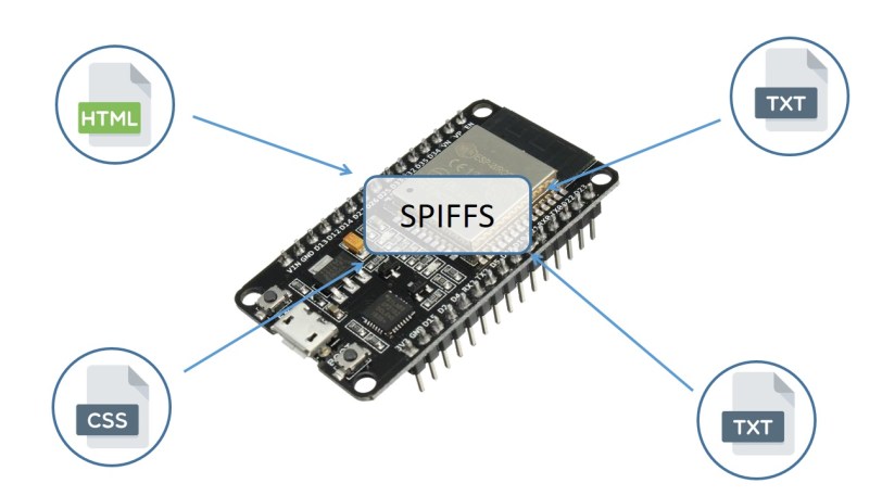
In this article we''ll show you how to upload files to ESP32 filesystem (SPIFFS) using a plugin for the Arduino IDE: the ESP32 filesystem uploader.
Naturally it needs another library, but SPIFF seems to work similar to a traditional file system and includes wear leveling. https://github.com/pellepl/spiffs

And here's the drop from Espressif who makes the boards: https://github.com/espressif/arduino-esp32/tree/master/libraries/SPIFFS

GitHub
Arduino core for the ESP32. Contribute to espressif/arduino-esp32 development by creating an account on GitHub.
That's the route. Thanks for helping me find the magic keywords.
narrow thorn
release 1.8.10 is out.. https://www.arduino.cc/en/Main/ReleaseNotes
@mossy plume Check this out https://github.com/me-no-dev/arduino-esp32fs-plugin
GitHub
Arduino plugin for uploading files to ESP32 file system - me-no-dev/arduino-esp32fs-plugin
and if you are into leds and cool things you can do with an ESP32 and leds.. https://github.com/jasoncoon/esp32-fastled-webserver

GitHub
Work in progress ESP32 port of https://github.com/jasoncoon/esp8266-fastled-webserver - jasoncoon/esp32-fastled-webserver
I didn't have to do the SPIFFS fix at the bottom of the page. I think they fixed the mainline since Jason made his guide.
 undone oracle
Im having an issue with my arduino nano. I build a circuit on a breadboard, uploaded the code, and it runs fine. Then i put my arduino nano on my pcb and the RX and L leds light up. Not sure why it is doing this. Maybe i made a mistake while soldering?
 mild elk
Most likely. Triple-check your soldering @undone oracle
narrow thorn
use a light and magnifier. I once had a short from a single strand of multi stranded wire.. they are like the size of a hair! Was very hard to see/find. The board was so small that the wire insulation was touching each other.. It's cool how we miniaturize everything, but that creates a whole new set of challenges.
north stream
As I get older and my eyes get worse, electronics gets smaller. I would have been better off with teeny surface-mount stuff when I was a kid, and big chonky vacuum tubes now. Ah, well.
narrow thorn
We all need to pull a Benjamin Button
undone oracle
Thing is, when i first plugged in the pcb, it was working fine for a second. Then the rx and L leds light up
Do i have to burn off all excess flux?
north stream
Depends on the flux. Some fluxes are a bit conductive and should be cleaned (generally not burned) off after soldering.
undone oracle
Interesting. The first pcb i made failed i didnt use any flux on that one. Then i made a new using flux and it worked for only a second. I think i have to program the chip to turn off the rx led
What should i use to clean the flux? Rubbing alcohol?
north stream
Again, depends on the flux. Alcohol will work for some, others need a saponifier.
narrow thorn
I have never seen a fux or rosin core solder tell you what was needed to clean off the flux. I just "assumed" that rubbing alcohol would always work.
 vernal sail
Hey everyone! I've run into some issues with Uno in Assembly. I'm wondering if anyone have some insight perhaps..
Basically i'm trying to read a value from PIND, which has worked flawlessly in the past.
The basic gist of it is that i set the DDRD to input by masking it with
0b1101_1111 or 0xDF
However when i'm reading PIND it returns 0x09 in the simulator for no reason.. I've tried manually setting it to 0x20 but it's overwritten..
I don't get why PIND5 would return 0x09..
vernal sail
yeah i'm only reading from it
 pine bramble
Did you turn on the clock?
the gpio clock
I dont know if its has a gpio clock
haha
pine bramble
the clock ?
haha
nmice 😛
👌
You were lucky I just learned that from a course haha
😂
vernal sail
me and my pal sat in the lab for like 2 hours struggling..
my issue was
ldi READ_INPUT, PIND
instead of
in READ_INPUT, PIND
vernal sail
been at it for like 6 hours today.. a whole day of assembly takes its toll
pine bramble
Is it fast ? with assem?
vernal sail
yeah magnitudes faster
pine bramble
yeahh that's the moment when you have to realize you have to stop. because doing more will do more damage haha
nicee!!!
undone oracle
@narrow thorn @north stream @mild elk after cleaning the flux, it works like a charm! I successfully created my first PCB!! Thanks guys for the help guys!😃
pine bramble
Nice xD
vernal sail
this should say something about the speed of assembly xD
mild elk
@undone oracle nice ;)
undone oracle
@mild elk thanks
mild elk
What does it do?
undone oracle
Its a solar tracking system, it orientates a solar panel to ahieve maximum sunlight @mild elk
@pine bramble thanks
mild elk
This is great 😃
Really good idea for a first project
I just finished writing a software update for my clock
It adds support for DS3231s aging offset register
vernal sail
cool projects guys
mild elk
By holding a button when powering it up you can access a secret menu that lets you manually change the value
So if I notice that it's running fast I can slow it down by modifying that register
undone oracle
Oh thats cool. I plan on attaching a DS1302 RTC to give my motors some more movement
pine bramble
Nicee ! 😛
mild elk
@undone oracle go with DS3231 or DS3234. They are the best of the best. Really accurate and easy to use.
undone oracle
Yea i wanted to use the DS3231 but my local microcenter only had the DS1302
mild elk
I encourage you to get your hands on one. It's one of my favourite ICs
I can even share my code
Also: don't bother with pre-made libraries for DS3231. They are a waste of time from my experience. Have a good read of the datasheet and write access routines using just wire library. It will save you a lot of frustration.
@undone oracle
undone oracle
Awesome👍ill look into it
 elder hare
With the adafruit_neopixel lib they all ran at the same time but i switched to fastLED and now you can see they run uneven :( why?
im running the "Theater Chase" pattern btw
narrow thorn
hard do say without the code and how they are wired up.
maybe put the code on pastebin and give us a link and describe how you have them wired up, what the controller is etc
 next siren
hello all. new to the whole thing here but trying to get the lcd 16X2 wired up to an itsy bitsy m4. i was getting intermitten flashes on the backlight now nothing
was following the wiring a character lcd tutorial
 wintry berry
Hi,
Is there a way to connect RTC module and OLED to arduino nano at the same time using the same i2c pins?


 solar sail
Multiple I2C devices can share the same bus as long as there isn't address contention and the voltage is the same (otherwise you'll need voltage translation)
next siren
please dont be too harsh lol
ive tried connecting the lcd and backlight to both power supplies, the 3v and the vhi
and got some flickering
ive also tried with and without the resistor
rocky igloo
@next siren The tutorial for character LCD modules looks good and is very detailed. Are you following that? If you are, where are things going wrong and not matching what you expect to happen? https://learn.adafruit.com/character-lcds/overview

I haven't used exactly the module that Adafruit sells, but from my experience with them generally they are very touchy about the contrast adjustment. I absolutely needed to use the potentiometer to set that and it had to be set just right. Set too low, nothing appears. Set too high, the display is all white.
next siren
thats the guide there ive been trying to follow
basically i can get the screen to flash. im just still trying to get the backlight to display
next siren
super stuck im trying to use the power rails now but nothing gets the backlight to stay on and going further with the the meter i tried and went back as it dint seem to help
could it be the board not holding or passing the charge?
is it possible that the itsy bitsy being 3.3 v dosent have enough power to run it?
north stream
Which pins are you using for power and ground? Have you tried it without hooking up the power leads for the LCD? Why is the resistor there?
next siren
i got rid of the resistor. it was in the original guide i was using
i have tried the 3v, vhi, and usb for power sources
both directly and through the power rails
im starting to think the issue is voltage related
the itsy is 3.3v and the lcd must be 5v
i think its one of the only adaruit lcds so its weird they dont have something compatible with the itsy bitsy m4\
is there a recommended lcd for this chip?
north stream
I think it's a bad wire, bad connection, or bad LCD.
next siren
ill switch some stuff around
can you use a 5v lcd off a 3.3v microprocessor?
i guess by some mods but straight up?
north stream
Depends. Some LCDs will work fine that way. But you should probably figure out what the problem with the backlight is first.
next siren
wouldnt the backlight not power on though or not stay on if the volts wernt sufficient
north stream
That's one thing I'm trying to figure out. If you use Vusb, it should light right up and stay lit. If you use the 3V output, it should still light, but dimmer.
 sharp idol
heya
i am working on a smart watch and my ESP32 Wrover constantly resets every time it connects to the display ( a gameduino3 )
wintry berry
@solar sail thanks!
sharp idol
Nvm, my library was built for Arduino so it isn’t using the right spi protocol
 surreal pawn
How fast can the display on the hallowing m0 be run? I think I'm doing SPI at 12mhz now and I'd like to do at least 16mhz
 cyan jasper
can i not do this on arduino environment? mplab (xc8 with PIC) didn't mind. How can I solve this? (since double is 4bytes iirc, so couldnt figure out doing with 4 seperate bytes.)
Please ping me just in case I forget about it
 limpid ether
how do i use the trinket m0/pyruler's capacitive touch with arduino?
looks like there's an Adafruit_FreeTouch library for the actual capacitive pins
but apparently one of the buttons doesn't actually use capacitive touch and is instead a hack :/
...k
    t0_count = 0
    t0 = touches[0]
    t0.direction = Direction.OUTPUT
    t0.value = True
    t0.direction = Direction.INPUT
    # funky idea but we can 'diy' the one non-hardware captouch device by hand
    # by reading the drooping voltage on a tri-state pin.
    t0_count = t0.value + t0.value + t0.value + t0.value + t0.value + \
               t0.value + t0.value + t0.value + t0.value + t0.value + \
               t0.value + t0.value + t0.value + t0.value + t0.value
    cap_touches[0] = t0_count > 2
@cyan jasper I'm not sure I understand: the code you show does do it as 4 separate bytes, and should work in the Arduino environment. You should also be able to use ```c
EEPROM.get(read_address, a);
It does bit by bit because that's how I see in examples
I read bit by bit and shift the bits
 pulsar charm
Has anyone ever managed to use an OO class method within a callback function?
cyan jasper
@north stream gives out this error
invalid operands of types 'double' and 'int' to binary 'operator|'
north stream
Oh, tricky. For floating point values, you'll have to do it a little differently.
cyan jasper
EEPROM.get(read_address, a);
this works
well, compiles
IDK if it works yet
The part I didn't understand I didn't have to send pointer to a instead i just send a. pointer would make more sense. 🤔
But thank you very much@north stream
north stream
It's a little odd (it's apparently doing some stuff under the hood for you, like taking the address and calling sizeof() and so forth).
I just lifted the code from https://www.arduino.cc/en/Reference/EEPROMGet
 mint island
I am trying to upload the blink example to a Adafruit Circuit Playground Express. The board and port seem to be recognized. When I start an upload, the board goes into bootload mode but never runs the sketch. Eventually, I get the error messages below.
Suggestions?
Arduino: 1.8.10 (Windows 10), Board: "Adafruit Circuit Playground"
Sketch uses 3868 bytes (13%) of program storage space. Maximum is 28672 bytes.
Global variables use 149 bytes of dynamic memory.
avrdude: butterfly_recv(): programmer is not responding
avrdude: butterfly_recv(): programmer is not responding
avrdude: butterfly_recv(): programmer is not responding
avrdude: butterfly_recv(): programmer is not responding
avrdude: butterfly_recv(): programmer is not responding
Found programmer: Id = "�"; type = �
Software Version = i.
 inland crag
it looks like you have arduino set to program the circuit playground classic not the express
do you have "Adafruit SAMD Boards" installed?
@mint island
 fickle night
Hello again, folks. I'm trying to work with the little 8ohm speaker I've attached to A0 on my HalloWing m4 and I'm not having a whole lot of luck getting it to work. I've been analogWrite-ing random values and various things I've come across to A0 but no love. Any sample c++ code anyone has handy?
surreal pawn
The m0 hallowing sample code might be worth a try

Adafruit Learning System
This is Hallowing..this is Hallowing... Hallowing! Hallowing!
rocky igloo
@fickle night You could try to adapt the NeoTrellis M4 synth demo. https://github.com/adafruit/Adafruit_NeoTrellisM4/blob/master/examples/trellis_synth/trellis_synth.ino
GitHub
Example sketches for the NeoTrellis M4 board. Contribute to adafruit/Adafruit_NeoTrellisM4 development by creating an account on GitHub.
It uses the PJRC Audio library which supports the SAMD51. https://github.com/adafruit/Audio/
GitHub
Teensy Audio Library. Contribute to adafruit/Audio development by creating an account on GitHub.
fickle night
Thanks, guys. I'll give both things a look over. I really appreciate it!
 minor flax
I'm interested in the M4, but not in CircuitPython.. I want to stick to Arduino, as well as doing lower level/native AVR stuff... has anyone done this? Is getting a regular arduino bootloader easy enough?
mild elk
You can make your own arduino really cheaply, but I don't think there is something as powerful as the M4. But if you make your own arduino you can use other microcontrollers that are not supported by default, for example ATmega328PB or ATmega1284P. If you want to stick with low level arduino C++, I don't think you will ever fully utilize M4s power.
@minor flax
minor flax
@mild elk I want built in USB support and 2 UART's minimum, so I think that's either SAMD21 or SAMD51... ATMega doesn't have a chip that meets that requirements according to the Microchip selection tool. (I notice SAME51 also has CAN bus support which is needed, but I could do that with the more-supported SAMD51 and Arduino CAN libraries.)
mild elk
There is ATmega32u4 with native USB
It does only have one UART though
minor flax
Yeah I have the 32U4, but I need two UART, one for CAN, one for LIN, so I started looking at the SAM series. I could try and play with Python but I've barely touched it, so it would probably add some overhead. Plus I'm assuming the ecosystem might need to catch up, although I did notice CAN support in MicroPython.
mild elk
Alright, that makes sense
minor flax
So I'm back to the original question if running the basic Arduino environment (PlatformIO actually) is doable. 🙂
But it looks like in the documents it says even with the default UF2 bootloader it should be Arduino compatible.
north stream
There are several choices with two UARTs. SAMD is one possibility, but hardly the only one. I'm not sure why you're mentioning UF2, I don't the the Arduino environment cares about that mechanism.
minor flax
@north stream I think the M4 Grand Central express comes with the bootloader flashed. I guess if I'm programming via the programming pins then the bootloader wouldn't matter.
I did want to stick to "something" in the Arduino compatible world as it will be much more attractive to others who want to try out the design/project versus if it's just an AVR needing Atmel Studio and deeper knowledge.
north stream
Understood. Fortunately, there are Arduino plugins for a variety of architectures. I built one multi-UART project using Energia (an Arduino clone that supports the MSP430 chips). There's even an original style AVR-based Arduino with an extra UART (ATmega328PB).
minor flax
I'll go with the M4 grand central... it would lend itself to possibly native CAN support of the ATSAME21* variants if I want to go down that path.
north stream
It's a much more powerful chip than the AVR ones, and as you point out, has a bunch of useful built-in peripherals too.
narrow thorn
the grand central is a really nice board. With all the extra space, output/inputs it's really nice for prototyping and it's a lot smaller than I thought it would be. No it's not small compared to a feather or istybitsy.. but it's smaller than I thought it would be.
I seem to be turning into a bit of a board collector 🙂
minor flax
😄
 safe shell
If I set a pin as INPUT, I can digitalRead() it fine. But if I then analogRead() it, subsequent digitalRead()s will be wrong. I can't find anything discussing this scenario, or a step to change a pin b/t analog and digital reads. Am I missing something obvious?
(First time back in Arduino after a couple of years... I was pretty rusty)
rocky igloo
@safe shell This is where I always end up reading the source. The ATmega code is different from the SAMD code but it's all pretty simple.
Basically packages/arduino/hardware/avr/1.6.15/cores/arduino/wiring_analog.c and packages/arduino/hardware/avr/1.6.15/cores/arduino/wiring_digital.c for ATmega...
safe shell
Thanks, I'm on an ESP32. I may be chasing the wrong problem, even switching to OUTPUT then back to INPUT between the digital and analog reads doesn't fix it.
minor flax
@safe shell analogRead will probably set the pin to analog in the function call, so you need to set it back to pinmode digital again.
safe shell
pinMode(pin, mode) doesn't seem to have that option. I haven't found any other function to do it.
oops, some of these pins aren't output-capable and crash the ESP32 if I try o_O
safe shell
Fixed a few things and concluded all that's necessary is to re-pinMode(p, INPUT) after an analogRead to re-init it for digitalRead.
 humble ravine
hello! Has anyone had any experience programming an arduino with an ESP-01? i'm looking to experiment with sending the arduino commands over the internet and having a hard time finding an example of that
safe shell
@humble ravine Are you going with the AT firmware (e.g., https://www.instructables.com/id/Getting-Started-With-the-ESP8266-ESP-01/ ) or Arduino with WiFi library (e.g., https://create.arduino.cc/projecthub/ROBINTHOMAS/programming-esp8266-esp-01-with-arduino-011389 )?

Instructables
Getting Started With the ESP8266 ESP-01: The ESP8266 ESP-01 is a Wi-Fi module that allows microcontrollers access to a Wi-Fi network. This module is a self-contained SOC (System On a Chip) that doesn’t necessarily need a microcontroller to manipulate inputs and outputs as y...

Arduino Project Hub
ESP8266 is an impressive, low cost WiFi module suitable for adding WiFi functionality project. By Robin Kanattu Thomas.
humble ravine
i managed to get the AT firmware working in the first link
the second link i found confusing and needed something simpler.
i suppose i could take a second stab at the second link. was just hoping I could find an example of programmatically using the ESP-01 without changing the firmware
 hollow helm
Can someone please explain the difference between https://www.adafruit.com/product/2772 and https://www.adafruit.com/product/3403 ? They look identical, and they have the same processor and other specs.

Feather is the new development board from Adafruit, and like its namesake it is thin, light, and lets you fly! We designed Feather to be a new standard for portable microcontroller ...

We love all our Feathers equally, but this Feather is very special. It's our first Feather that is specifically designed for use with CircuitPython! CircuitPython is our ...
minor flax
One has flash memory
safe shell
@humble ravine It may be possible to put NodeMCU (Lua scripting language) on it, or some other environment. I don't know much about those. My 8266s were shipped with NodeMCU, but I quickly wiped them over to Arduino.
hollow helm
Is the latter the only Feather that can run circuit python, or can they both run it?
humble ravine
@safe shell ok, I'll check out NodeMCU. thanks!
minor flax
@hollow helm Not sure but since they are both the same price I'd go for the one with the flash memory.
safe shell
@hollow helm There are other Feathers that work with CircuitPython: ~~ https://learn.adafruit.com/adafruit-feather/feathers ~~ M4-based will have more RAM and more flash, if needed.

sorry, wrong link... https://learn.adafruit.com/adafruit-feather/circuitpython ...plus there's a HalloWing M4 now (and a bunch of non-Feather CircuitPython devices) ...better link of all the CircuitPython devices: https://circuitpython.org/downloads
CircuitPython Organization
hollow helm
Oh wow, thanks!
The guide I was using (https://learn.adafruit.com/how-to-choose-a-microcontroller?view=all) didn't mention the M4 Feather
Thanks, this is much better
rocky igloo
@hollow helm I can confirm that the Feather M0 Basic Proto does run CircuitPython, but it's very limited without the extra flash memory chip. There's hardly any space left for your program. And the Feather M4 is indeed a very nice board.
cyan jasper
Anyone know a RTC library for DS3231 that doesn't use some sort of time library/class and implements alarm functions?
north stream
@mild elk suggests just rolling your own.
mild elk
Exactly
I can even provide code example that uses nothing but wire library to interface DS3231
north stream
The chip is fairly simple to talk to, and will do the alarm functionality for you.
mild elk
All you have to do is read the datasheet
Please ping me if you're interested in my code.
@cyan jasper
I might consider writing my own library once I learn how to do it and when I'll have some time to spare
cyan jasper
I just wanted a library that i can call like rtc.year() and it returns year register
not like complicated constant DateTime objects
not that complicated but that's not what I want
@mild elk TBH I started to consider writing my own code from wire library
mild elk
My code example fetches data from DS3231 and updates corresponding variables when getDateTime() function is called
cyan jasper
maybe even jumb back to avr/twi
would be awesome if you could give corresponding part
mild elk
Give me a sec, I'll get my code since I forgot to upload it to my OneDrive :/
cyan jasper
not a git user?
north stream
It should be possible to support both with a little #ifdef code: while the different libraries support the same methods, the objects have different signatures.
mild elk
@cyan jasper
cyan jasper
♥
mild elk
Make sure to ping me if you have any questions. I can also add some other functions to have you understand the working principle
cyan jasper
ovvv
this doesn't have comments
well maximum effort
@mild elk what is wire1.h?
it was wire?
cyan jasper
is it i2c bitbang?
if so I kind of need that too, at some point id like to migrate this thing to Atmel Studio
😁
mild elk
no, it's for second I2C on 328PB
north stream
I like that chip, but a bit-bang mode would be handy as well.
mild elk
@cyan jasper this should be the correct version
mild elk
Which one? 328PB?
mild elk
It's just a regular 328 with some additional I2C, SPI, UART and digital pins
Like 328 version 2
cyan jasper
yeah but even 328 is plenty for %90 of people
I tend to go cheaper/smaller route with these type of things ^_^
mild elk
1284 I'd call powerful
128k flash
4k EEPROM
16k RAM
32 I/O pins
328PB is just as cheap as regular 328, but things like two hardware UARTs often come in handy
cyan jasper
can imagine
mild elk
Sure, It's not as easy to set up as a regular Arduino
But if I did it then anyone can
cyan jasper
well, you always can move to atmel studio 😉
mild elk
Does it run on Raspberry Pi? Because that's kinda the only computer I use
Also, what about my code example? Does it work now?
@cyan jasper
cyan jasper
I think they don't even have linux version
manufacturer utilities they don't really care linux or osx
oh IDK I'm still merging your code and my code
mild elk
Alright
Also: if you want to set a value into a register, instead of transmitting the address, ending the transmission and requesting a byte, you just transfer the register address, then the value you want to write into it and then end transmission. All register addresses and functions are well described in the datasheet
undone oracle
Does anyone know what kind of lipo battery i can charge using this solar panel?
mild elk
Short answer is none
Long answer is that it only outputs 0.5V and you need I think 4.2 to charge a li-po
And you cant directly connect it and expect it to work. You need some kind of charging circuit. @undone oracle
undone oracle
@mild elk i already have a lipo charging ic
@mild elk what about this solar panel?
mild elk
Well, the second panel has too high voltage for your charge IC. I has USB input so it probably expects 5V
undone oracle
Huh so i should return these panels and buy another one?
mild elk
I would suggest connetcing 10 smaller panles in series
undone oracle
I just need enough charging power to power 2 LEDs
So maybe i need a smaller lipo battery?
mild elk
Battery size doesn't matter. It's nominal voltage will always be multiple of 3.7V
mild elk
If you connected 10 smaller panels in series and used them to power charge IC it wolud charge your battery in about 4 hours
7.2 is indeed too much
undone oracle
What if i buy a 5V panel?
mild elk
You could use a buck converter but it wastes your precious clean power
Well 5V panel does the trick
undone oracle
I dont want to use alot of panels, i just want to mount 1 panel onto my bicycle which powers a battery that turns on red LEDs at night
Maybe ill get a smaller battery and a different panel
mild elk
200mAh battery should be enough
undone oracle
Why are all/most lipo battery 3.7v?
mild elk
Because of the technology
It's like asking why AA batteries are 1.5V
undone oracle
So if i need a 5V power source, a 3.7V battery wouldnt work as a power source?
In other words, can i use a 3.7V lipo battery to power an arduino nano? I think i read somewhere that the nano needs requires a 5V operating volatge
mild elk
Well, no and yes
You can't just power a stock nano like that, but with some small modifications you can pull that off
mild elk
What do you expect this to do
undone oracle
Use a solar panel to charge a lipo battery which powers a LED circuit
mild elk
Do you have that 5V panel?
undone oracle
No i need to go buy one
Bc the one i have is no good
I may also buy a different kind of lipo battery too
I think it should go
Panel --> ic
ic --> lipo
Lipo --> led circuit
mild elk
Panel's red wire to + input on charge IC
Panel's black wire to - input on cahrge IC
Li-po red wire/+ terminal to + battery input on chare IC
Li-po black wire/ - terminal to - battery input on charge IC
Battery connections are also your output terminals
And don't overdischarge the li-po because things might get nasty
undone oracle
Lipo says it has overcharge protection
mild elk
I said overdischarge
mild elk
Then you should be fine
undone oracle
How come some wires have multistrand wires and others have single strand? Do you know what i mean?
mild elk
There are no dumb questions, only dumb answers
You mean solid core and these ones with tons of thin copper wires inside?
mild elk
Single strand are less flexible but can carry more current than the same thickness multi strand wire
undone oracle
This is hard to see, but its multi stand and connected to the panel i bought
So theres literally no difference?
mild elk
For your application yes
undone oracle
Ok and i can cut the pre made wires/usb connetion on the panel and solder my own wires right?
mild elk
Yes
mild elk
Correct, just make sure it's 5V and that you get the polarity right
undone oracle
@loud wing this the charging ic im using
mild elk
If you swap + and - your charge IC will get destroyed quicker than you can say "oh snap"
mild elk
I see that polarity is clearly marked on the pcb
 loud wing
also you need to consider a different charging circuit
the TP4056 is great but for solar you should look at ones that use a different IC
eg. Adafruit Solar Lipo charger
undone oracle
This is the only charging circuit microcenter has
loud wing
I think Microcenter carries adafruit stuff too?

NOTE: This product is only designed for use with solar panels sold at the Adafruit store. We cannot guarantee this will work with solar panels purchased elsewhere. Please purchase this kit ...
something like this
mild elk
I guess it should do the job
We just want to light an LED
undone oracle
Basically i want to charge a lipo with a panel, but the panels they sell at microcenter arent great.
 frail pawn
if you find a 5v panel you can probably use that charging circuit
loud wing
@undone oracle https://www.youtube.com/watch?v=dBx-g1dkdDQ
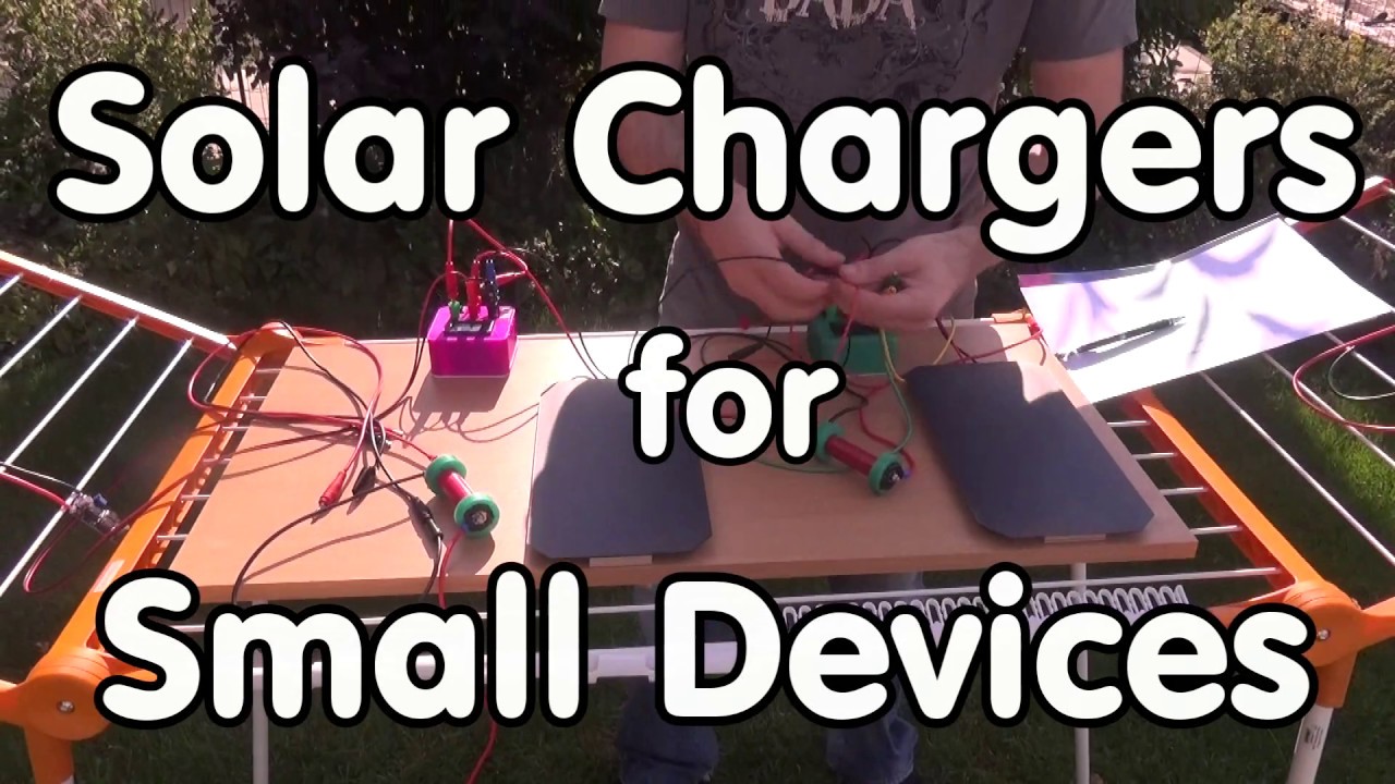
In video #142 we started a journey to power or small devices with solar power. Today, we continue this journey. We will - Have a look at the available boards...
frail pawn
though the tp4056 says maximum voltage is 8v it might cause issues with whatever else is on the little board
loud wing
The video references his other video which describes panels
In video #142 we started a journey to power or small devices with solar power. Today, we continue this journey. We will - Have a look at the available boards...
this one links to the TP4056 bit
undone oracle
This is my first attempt, so i dont want to overcomplicate the circuit. I just want to make sure i can make something that works. Then i can add an arduino to it etc..
mild elk
You need a modded arduino to run directly from a lipo
loud wing
I don't think the video is about adding more to a circuit... it's a review of the different chargers and how they behave.
It also covers some details that you might want to be aware of... the circuit and it's complexity remains in your hands
frail pawn
you would need to convert the voltage higher for the arduino anyway
oh kaktus said that, nevermind
undone oracle
Just got to microcenter
mild elk
You can burn 8MHz bootloader and connect li-po to 5V pin.
Just never plug the usb in when lipo is connected
loud wing
are those lithium batteries?
mild elk
They could be 3 ni-mh in series
undone oracle
Im confused bc the ic says its for single cell lipo batteries
mild elk
But the batteries you just showed us say "cordless phone battery" and these usually aren't li-po but rather ni-mh
loud wing
yep!
mild elk
And since ni-mh voltage is 1.2V, 1.2V * 3 = 3.6V
undone oracle
Ok now for the panel
loud wing
5V!
mild elk
^
loud wing
wish we had a microcenter here ~
undone oracle
Is 200mah good?
frail pawn
it means it will, in ideal conditions, supply 200ma
undone oracle
Theres also a 200mah, 3.6v panel
mild elk
You need 5V
undone oracle
Ok, would 400mah be better?
loud wing
Yep
mild elk
It would charge twice as fast
undone oracle
No idea
mild elk
I bet no more than 100mA
undone oracle
Thats why i wanted a smaller battery
mild elk
You can always change it
undone oracle
Ok so theres 2 5v panels here.
One is 200ma and the other is 100ma
Im getting the 200 ma one
mild elk
Yes
loud wing
Different Chemicals inside those batteries
undone oracle
Yea..
frail pawn
right short easy version, theres a bunch of different battery types, you specifically are looking for LIPO or LION
your 18650 is a lion
anything else is a no go
undone oracle
frail pawn
lipo usually look like flattish silver rectangles
loud wing
Is that a rechargeable Lithium? or just lithium
frail pawn
also no, the charger youhave is designed for a single cell 3.7v
undone oracle
loud wing
non-rechargeable
undone oracle
Ohhh ok
mild elk
So don't get it
mild elk
It's the same as the one you already have
undone oracle
Yea but i like the color blue
Thanks for taking this trip to microcenter with me guys😂
frail pawn
np, for your project if you need less look for a flat silver battery with 3.7v on it, dont know if microcenter stock them though
loud wing
LIR2032 right @frail pawn ?
frail pawn
hmm i meant the rectangular onbes, i have no idea if his charger would work for the button cell, never looked
undone oracle
Yea but the battery i have is fine right?
frail pawn
probably bigger than you need, but should work
do you know if your battery has any sort of protection ?
loud wing
the recent photo above shows it has built-in charge protect
frail pawn
oh yeah i see, thats good
undone oracle
Oh well, i guess its go big or go home around here
frail pawn
its not really a problem unless you needed something more mobile, im using two smaller lipo batteries for my robot because hes only little 😛
loud wing
🇨🇦
undone oracle
ah
mild elk
Alright guys, I'm going to sleep
Bye!
loud wing
@mild elk Good night!
undone oracle
Night, thanks for the help. Really appreciate it @mild elk
undone oracle
Question,
If im using a 3.7v lipo battery to power am arduino uno, which pin do i use for power? 3.3V, 5V, or Vin?
inland crag
Vin I believe
mild elk
Vin only accepts 7-12V I think
You need a modded arduino to run at 3.3V
Or use a 3.3V pro mini
undone oracle
Interesting, it only seems to work with the 3.3V pin
This is gonna be an interesting project, i finally made a functioning circuit. Tomorrow i will solder the PCB and pray that the solar panel charges the lipo
The IC does have a few led indicators. So ill test that out
But now its time for bed. Goodnight everyone
mild elk
???
3.3V pin is an output from onboard regulator
Maybe if you connected it to Vin nothing happened because it only accepts 7-12V
And on 5V pin maybe it was drawing so much current that usb port shuts down
I'm telling you: you need a modded arduino or 3.3V pro mini
undone oracle
Um heres the thing...
My circuit uses the 5v pin for a push button. Idk why, its just how the schematic works.
I can show you everything tomorrow
mild elk
Sure
 covert sky
I am attempting to use the bmpDraw(bmpfilename, x, y); of the ImageReader library. However I'm having issues creating a dynamic bmpfilename for example I was to display image1.bmp, then image2.bmp and etc.
In the .h file I can see ImageReturnCode drawBMP(char *filename, Adafruit_SPITFT &tft, int16_t x, int16_t y, boolean transact = true);
covert sky
I figured it out.. baseFile.c_str()
undone oracle
Hm, it doesnt seem to be doing anything
Oh nvm
When i shine a light on the panel, a red led turns on on the ic
Indicating that the battery is charging
undone oracle
Is it ok if i solder a wire directly to the postive end of the battery
pine bramble
@undone oracle Everything I've read says you should be very careful when soldering to a battery as it could explode. I would recommend a battery holder.
pine bramble
When they're not you may well pursue one that is. ;)
undone oracle
True
pine bramble
I usually don't think about the easy ones during my time away from the bench.
As you age, redoing an old one you've totally forgotten how it works -- becomes a recreation (hah, literally).
undone oracle
Inovation👍
pine bramble
I redid a dotstar (apa102) driver the other day, this time in Arduino IDE. Took a few hours, but the entire time I was pretty sure I had nothing think about, so much as just finding things I already understood. It was pretty satisfying to 'knock one out' and get it done in an evening. Pretty unusual.
(oop, accidentally on-topic haha)
Now I'm going to redo it again, written entirely in Forth. ;)
cyan jasper
This might sound stupid buuuut is there a way to check available memory on arduino while in sketch? I know it says how much left for variables when you compile but I want to adjust my array size on the fly
 burnt island
I don't think so. I don't think there is any dynamic memory allocation in arduino
cyan jasper
found it
there is a library for that
technically its supported by arduino
for now I'll try not to bother with it
 errant geode
What can i do if my libraries are bigger than 1MB? And my esp does not have enough space to contain them? Also i read somewhere that esp32 has 4MB flash, but platformio thinks that t have only 1MB.
loud wing
@errant geode 4 Megabit vs. 4 Megabyte
@errant geode you can use an external flash storage? like a microsd or spi flash
errant geode
Sd for code?
loud wing
is your esp32 a module?
@errant geode https://www.esp32.com/viewtopic.php?f=12&t=1738 might be related to your query
Espressif ESP32 Official Forum
if you are using arduino, IIRC you are able to determine how much of the flash is used for code vs. other stuff
errant geode
Yes. I change partitions size from 1MB to 2MB (i got answer on another discord), but my program uses 1.5MB with only libraries. It is ok for now, but if i add more code...
loud wing
your solutions can be the following (but not limited to):
1.) Optimizing your code so you don't reach that limit.
2.) Upgrade the ESP32 flash internal or external
what are you building @errant geode ? if you don't mind me asking
errant geode
something like... smartwatch
loud wing
cool 🙂
errant geode
Can someone explain me why esp32 lite does not have scl and sda pin for i2c communication? And how to connect i2c device to this?
Nevermind, I found that i can Wire.begin(SDA, SCL) with any pins.
pulsar charm
I just saw a little bit of code in a scheduler library that defines 211 microseconds like this:
#define T1_INIT (211L)
can someone explain what does the L refer to?
is this a shorthand for (long)211?
 untold elk
hello all
looking for a little help. I got my arduino working with astepper motor and a joystick I want to write a program that allows me to toggle between manual control and a auto program that will allow the motor to loop a specific set of movements endlessly. Is this possible?
pulsar charm
@burnt island Thanks! I'll google that up!
pulsar charm
Oh the magical lands of C
north stream
@untold elk It's doable, but the tricky part is checking for manual input while cycling the stepper motor. It boils down to the same "multi-tasking" approach used in other situations where you want the processor to (appear to) do multiple things at once. https://learn.adafruit.com/multi-tasking-the-arduino-part-1
 atomic bay
Arduino only has 1 thread?
north stream
Yeah, it's a fairly simple CPU, but it's possible to write a simple scheduler for it (several people have done so).
untold elk
thx mad
mild elk
I honestly think it's better that Arduino (ATmega328 or other) has only one core because it's easier to program and also there wouldn't be many people that would benefit from multi core performance. I'm not even sure how multi-core programming would look like on Arduino
north stream
For multi-core type stuff, a Propeller is a popular choice.
pulsar charm
@untold elk I use a library called TaskScheduler which is a software scheduler
What is Propeller?
north stream
The Propeller has co-processors (known as "cogs") to take care of tasks while the main CPU is doing other things. https://dev.to/evantypanski/parallax-propeller-chip-for-programmers-9c0
untold elk
Thx lackdaz
pulsar charm
Fascinating, have you used any parallax propellor boards yet?
I was just doing something with the scheduler today, and was trying to implement task prioritization. Didn't end up well
I was running 4x pid control whilst juggling stepper control and some other sensor controls.
The software scheduler library I used worked well enough juggling a few simple sensor inputs and the stepper without jitter (context switch for an uno is about 15 uS, I was running the stepper at a 200uS duty cycle).
The multiple PID control though, were very expensive and caused me to rethink about the use of microcontrollers to do too many things at once. It'd be nice if I could try this out with the propellor or one of those pseudo-parallel DUE/MKR boards
north stream
I haven't personally used a Propeller board, usually I just use fancy coding or multiple boards when I'm doing more than one thing at once. However, the Propeller seems like it's designed for such use.
cyan jasper
Can I use ArduinoISP to read EEPROM of another uC (probably atmega328p without external oscillator, also considering downgrading the chip so itd be so nice if it just works)
I found AVRDude can do it but I don't know if i should specify certain parameter to it for ArduinoISP
Also found AVRDude gui (avrdudesss) it has 2 options named "Arduino" and "Arduino: FT232R connected to ISP" maybe one of those could work for it but not sure
PS. I know I should be reading more on AVRDude at this point but I am kind of exhausted trying to find the right information online.
undone oracle
@mild elk @frail pawn @loud wing @inland crag GUYS!!! it works! When you push the button the 4 leds start blinking so cars can see me while im riding my bike at night. The solar panel is connected to a 3.7V lipo battery which powers the arduino
mild elk
Hey, that's great! I'm glad you got it working
undone oracle
Thanks 😁 and thank you for the help. Couldnt have done it without you guys
At night ill record a video if it working and i post it here
frail pawn
Awesome!
mild elk
Also: tomorrow I'm releasing my DS3231 library, anyone interested in checking it out?
I'll post a link here as soon as I finish it
cyan jasper
@mild elk may i get a ping when you release it?
mild elk
Sure
cyan jasper
when you're around can you take a peek question above? @mild elk ^
mild elk
I think I saw some sketches that could perform some advanced ISP stuff like burning .bin files from SD card, although I'm not sure if one of them could read EEPROM data
Give me a sec, I'll look into that
cyan jasper
thank you man
mild elk
No, seems like the sketches I was thinking about cannot do that. So you have three options: do some searching and hopefully find whay you want, give up or create something like this yourself
north stream
My understanding is that ArduinoISP simply uses an Arduino as an intermediary to allow access to another CPU. It seems like it ought to be possible to do something like avrdude -p m328p -c arduino -U eeprom:r:eeprom.dump
(along with the appropriate other flags for port and so forth)
undone oracle
Now im mad😡 turns out i used some cheap 50 cent jumper wires instead of good ones and they broke. Now i have to replace them😒 🙄
 waxen flare
Has anyone ever written an app to control their arduino board? like, through bluetooth or something?
north stream
That's kind of what Blynk does.
cyan jasper
IDK anyone else is as crazy as me but you can use arduino as ISP with avrdude just gotta add some stuff to .conf file for future reference. I'll check with avrdudess and update.
https://forum.arduino.cc/index.php?topic=535617.0
@undone oracle try out length (cut) whatever those jumpers called (the ones that doesn't come as rainbow ribbon) the wire is quite nice even if its cheaper. And for breadboard you wont get lost in pack of wires.
@waxen flare I am starting an app that control/read from arduino with qt over USB serial but you could probably change it to any other serial (Bluetooth if you want) probably can share when im done with it if you want (gotta ask teacher first).
waxen flare
hmm sounds good to me. I'll look into QT
cyan jasper
It's CPP which is almost arduino
cyan jasper
@north stream was -c arduino for arduino as isp to something on breadboard or to program uC on arduino?
gui doesn't work non gui programs chip on arduino, arduino IDE does same
north stream
The -c option controls which programmer to talk to. I'm guessing "arduino" is for arduino as ISP, but I'll admit I'm not sure. One nice thing about the Arduino IDE is you can see the command it's issuing and copy-paste them somewhere, edit them, and run them directly from the command line. I'll usually do that to get the bulk of the correct command then modify/add whatever arguments I need to.
cyan jasper
Naaah I think I get scammed with my uCs
Their id doesn't match m328p's id
That's one of the error I got when I try to flash it
Or someone fried all of them
north stream
What ID do you get? If it's something like 0xff, it's more likely a communication error.
If it's something like 1e 92 10, it's a -PB chip, which is a newer, better version with goodies like an extra UART.
cyan jasper
I think it's 0x000
And can't be sure if something with wiring wrong or chip wrong or something with Arduino being funny
Because it's on breadboard
north stream
Yeah, 0000 seems like it could be a more basic problem.
Does it have a clock source?
cyan jasper
Actually it doesn't say 00000 straight up
mild elk
Here it is!
if You find any bugs, please contact me immediately either here or on github

GitHub
DS3231 library for Arduino. Contribute to K4ktus123/kDS3231 development by creating an account on GitHub.
@cyan jasper
cyan jasper
In past mega8 show an id these chips do not so I assumed that they send 0x000 and for Arduino that's like null
mild elk
so now please tell me if it downloads, installs and works
mild elk
oof
what's wrong?
north stream
I can download the repo, but I'm not at a place where I can test it right now.
mild elk
Alright, so at least that works
north stream
I don't think any chips would send 0000, which is why I'm wondering if there's some other problem impacting communication so avrdude is getting nothing back so it just reports 0000
mild elk
Yeah, 0000 is usually due to bad connections or dead chip
north stream
Heh, at first "git clone" didn't work, but that was because I had to accept a package license to execute git on the command line (silly Apple)
mild elk
I hope I included the license correctly
undone oracle
@cyan jasper thats for the jumper wire tips. I have really nice wires back at home i just need replace the cheap ones
cyan jasper
oh god tahts 2 now 😬
rocky igloo
@mild elk Here's an issue that's really easy to fix: More people will find your project if you include, "The DS3231 is a low-cost, extremely accurate I²C real-time clock (RTC) with an integrated temperature-compensated crystal oscillator (TCXO) and crystal." in the README. Also perhaps put "Maxim Integrated" in there somewhere. We do searches on stuff like that.
cyan jasper
might get kicked soon :/
@mild elk BTW I got problems with burning bootloaders or uploading directly with arduino as isp sketch
rocky igloo
@akir I just scrolled back a couple of pages and don't see a link to this page, which has always been my guide for Arduino ISP bootloader burning. Have you seen it? https://www.arduino.cc/en/tutorial/arduinoISP
Open-source electronic prototyping platform enabling users to create interactive electronic objects.
Arduino ISP was the second Arduino sketch I ever ran, right after Blink. Being able to use an Arduino to make a blank ATmega chip into another Arduino was the thing that sold me on the platform.
As @north stream says, if you're getting a chip id of 0000, you aren't getting any data from the chip. It isn't powered or reset isn't getting pulled down like it should or maybe you've crossed miso and mosi. It usually takes several tries to get it right!
mild elk
@rocky igloo alright, will do that
north stream
Also, make sure it has an appropriate clock source
mild elk
On ATmega series reset is active low so you probably want to put a 10k resistor acros reset pin and +5V
And if your chip has multiple vcc and ground pins connect them all to respective voltage potentials
Sometimes a chip might require 0.1uF ceramic capacitor across its power pins to work, a good example is 328PB
cyan jasper
@rocky igloo I know all those thank you for your effort. but arduino programs just the wrong chip when i try to directly program. I did all those things. I've managed to get it work before with bootloaders. It's just this batch of chips doesn't work. Tomorrow I'll try with oscillator just incase someone already bootloaded them. Also aim wasn't just flashing bootloader it was being able to use with avrdudees(avrdude gui) and dumb eeprom.
rocky igloo
@akir Sorry that didn't help. Good luck with it!
mild elk
Maybe your chip is DOA? Always buy parts from trusted stores. I get mine at TME
I really like how they pack all the stuff in ESD bags and for moisture-sensitive parts they even seal the bag with silica gel inside and moisture indicator card
It's just insane how much effort they put into making sure your parts are going to work no matter what they went through during shipping
This is ATmega8, right?
In DIP?
It should work just with 16MHz quartz on XTAL pins and some 22pF caps to GND
And as we already said check your connections
Did you put a 10uF electrolytic across reset and GND on programmer Arduino?
You can also try your setup with known-good chip if you have one
rocky igloo
@mild elk If you don't put the 10uF cap from reset to ground on the programmer, avrdude will report the chip id of the ATmega328p on the programmer. Guess how I know this. 😁
cyan jasper
@mild elk doa?
It's mega328p
Dip
I bought it from local microprocessor/chip vendor in a passage but that's pretty much where you go for anything you need resistors caps motors etc. Etc.
 slim shell
I could use some help with my CPX. Using the "Hello_Buttons" and "Hello_SlideSwitch" demo sketches produces odd results. The button sketch has the left button working and produces the correct Up/Down response in the Serial monitor when toggled. The right button always prints Down to the monitor, even when the button is unpressed.
The Slide switch sketch just prints a negative to the monitor. It will not print + when toggled. Occasionally it prints + when I touch the board, not just toggle the switch.
I have tried two boards, two usb cables, and two usb ports. One board is unused, but has been sitting in a plastic box with some other microcontrollers for a few months.
 agile anvil
I’m wanting to use an Arduino Mega with an ATmega2560 to power some LED strips that have WS2812B’s on them. I was going through the NeoPixel library ReadMe on the GitHub page, and it didn’t list the ATmega or Arduino Mega as a supported chipset. Instead it says to check the forks for architectures not listed here. Does anyone know if the original will support the Arduino Mega, or which fork(s) do.
north stream
I'm guessing it would work, or the FastLED library is another option.
errant geode
What is best to use if i want to make a lot of connections in very small project? Jumper wires? I mean, that i want to connect sd crad reader, touchscreen display, some sensors and other things to my esp.
north stream
Depends on which board. There are some nice breakouts for NodeMCU and Feather.
errant geode
I am want to make something like smartwatch, but i dont know how to connect all this things to my esp.
north stream
Usually the prototype is much larger to figure out how everything is going to work and what connections are required. After that is the usual time to miniaturize.
Are you looking for how to miniaturize in the short term, or ways to do it eventually?
errant geode
I want to connect all my sensors and other things to my esp, but i dont know how to do that. I think it must be cables. But what cables? Jumper wires works good, but take a lot of space. Simple wire is smaller, but it is hard to solder everything propearly for me.
north stream
For some things like I2C sensors, you might be able to daisy-chain them with Grove or Qwiic connectors.
errant geode
But this make the project too big. I want everything will fit in 5cm x 4cm x 1.5cm box.
north stream
Ah, you mean in the long run. Your best bet might be a flexible PCB that you attach everything to then fold it up to fit in the enclosure.
mild elk
Has anyone tried my libary yet? I know I'm impatient but I'm sure there are bugs it it that I didn't notice and I'd like to get them fixed
I'll also do some testing myself, but because I created it I have a higher chance of overlooking something
north stream
I'd have to dig up an Arduino, a DS3231, and some time. I think I have at least two of those.
mild elk
Arduino and DS3231?
Well I know that pain of not having enough time
Don't push yourself though, I can wait
 digital island
I have an intentionally incredibly stupid idea: I want to try to make a really impractical keyboard using a sparkfun Pro Micro, where you ground different pins to write letters, but since I only have 12 pins, I'll have to make it so you type a combination of two pins to make each character. Any help with the logic in between there though? (I know how to read pins and print characters, I just need a push in the right direction for how I can do the logic in between) (please @ me)
 mighty raft
@digital island FYI that's called a chorded keyboard. I've wanted to make one for a while. My plan is to assign a power of 2 to each button (pin) and then interpret their state as an integer, and then use a lookup table to match the state of the pins to a character (or word).
Hi! Tl;Dr I'm having a medical issue related to my sleeping posture. I'm thinking of making something that helps train me to sleep on my back & not my side, by waking me up if I start sleeping on my side. I'm wondering how I could detect which position I'm in? My only thought so far has been a giant capacitive sensor under my sheet, but that neither sounds comfortable nor reliable.
Ie, it's an environment with a lot of static, the potential is probably unpredictable
I'd also appreciate an @. Thanks!
rocky igloo
@mighty raft Face detection is something that most digital cameras do now. I get the impression that it isn't super hard, not nearly as bad as object recognition in the general case. Could you put a camera overhead, do some image processing, and trigger an alarm when it can't see your face? Dunno if you could free-ride on a camera's face detection. I know there are hacks like Magic Lantern firmware for Canon cameras. Or maybe do it yourself with a Raspberry Pi.
(Assuming infrared light/night vision, let's say...)
mighty raft
@rocky igloo hmm, thanks for the idea, but I feel like there must be a simpler, more analog way to do it. That seems a bit brittle. Like maybe my hair gets in my face, or the pillow, and there's a false alarm. Might be able to supplement it by wearing like a headband with tinfoil on it or something. But I feel like there must be a clever way to rig a switch or something like that.
rocky igloo
@mighty raft There are usually simpler and more clever ways to do things than what I come up with.😁
cyan jasper
@agile anvil It works they are actually same architecture both AVR and its arduino library so arduino natively supports their products
@digital island you want to make a key matrix? there should be a library for that I remember using a keypad with arduino pretty easily and reliably
cyan jasper
         Double check connections and try again, or use -F to override
         this check.

Error while burning bootloader.
would that give any idea to any of you?@mild elk @north stream @rocky igloo
I tried with clock too now
mild elk
What chip is this?
mild elk
It suggests to check all connections, so I encourage you to do that. Put 0.1uF capacior across VCC and GND pins. You are using Arduino ISP, right?
cyan jasper
oh god i hate breadboards
🤦
1E 95 0F finally read something
only had to do same circuit 3 times
mild elk
Loose connections
I never had problems like that
Always use quality breadboards
cyan jasper
I guess this is what happens if you steal from your brand new makerspace
I might literally be first person to use this bb
I think its non p model
just m328
wait avrdude says its ATmega328P too
waht?
north stream
These are handy for setting up chips for flashing if you don't want to fight with breadboards (add a ZIF socket for extra utility): https://www.adafruit.com/product/174

We took the business-card-sized AVR target board from Evil Mad Scientist Laboratories and added a few components to make an AVR dev board that has only the bare minimums!Comes unassembled ...
cyan jasper
for now I dont need that
I have my own green zif things but im not gonna solder that not yet
 icy cypress
Can I have help? I have an esp8266 and I am trying to flash some code to it. The ide can't find the serial port and no drive shows up when I plug it in.
The light only flashes twice
and then nothing happens
mild elk
Have you selected a correct serial port? What kind of usb to serial converter are you using?
Do you have correct driver installed?
mild elk
Also: you need to pull GPIO 0 low when powering up the esp to enter programming mode
 elfin elbow
any good examples of playing audio files on the MonsterM4sk (or some other SAMD51 board) I can have a look at? Done some searching, but haven't found any, unfortunately 😦
surreal pawn
I have a bad example on an m0
seems there's one for the m4 hallowing too
GitHub
Gaming library. Contribute to adafruit/Adafruit_Arcada development by creating an account on GitHub.
unfortunately play_tune() is blocking, so you can't continue to update the display while the sound is playing
I'm working on an hallowing m0 so I've modified the corresponding sketch to use a timer interrupt to output sound samples instead, but it likely won't play at the correct rate on m4 without changing the timer parameters
cyan jasper
what about timer interrupt to update the screen 🤔 lock it to 30fps
surreal pawn
I'd like to play more than one sound at a time eventually. I'd rather drop frames than audio
cyan jasper
makes sense but if you do interrupt sound then you won't be able to do anything else.
because it'll be on interrupt all the time when playing tone
(perhaps an i2s sound module would be perfect)
surreal pawn
I don't think you understand what I changed then
play_tune() is no longer blocking. it returns immedately after just setting the current sample index to zero
at 16khz a timer interrupt sends the next sample to the DAC, and increments the next sample index
cyan jasper
oh okay
surreal pawn
I also don't have enough memory to update the screen all at once. the m0 hallowing framebuffer would use the entirety of ram
128 * 128 * 2 bytes = 32KB
elfin elbow
Thanks for that - the plan is for a PIR to trigger the eyes of a MonsterM4ask and to play a sound. It does the voice changing simultaneously so it should be possible, but it's worrying if its blocking.
burnt island
from Arduino you should be able to setup the DMA engine to feed the DAC with fewer interrupts
surreal pawn
can you have two DMAs running at once?
I wanted to use DMA to update the screen
on the hallowing m0 you only get about 43fps if all you do is DMA pixels to the screen at the default 12mhz
I don't know what SPI is set to on the hallowing m4, but if also 12mhz you'd only get 13fps
looks like samd51 has MAX_SPI defined to 24mHz
GitHub
Contribute to adafruit/ArduinoCore-samd development by creating an account on GitHub.
so 26fps unless you override that
 verbal mason
Anyone know how I would code different gamemodes (each with a diff code) to be initiated when a specific button is pressed? I have the arduino uno
surreal pawn
on the documents tab look at the example code for the danger shield: https://www.sparkfun.com/products/retired/11649

The SparkFun Danger Shield mounts on top of your Arduino or [Arduino Pro](http://www.s
it switches between 7 modes
verbal mason
Is that for me or someone else
surreal pawn
for you @verbal mason
the demo sketch there has one button switch between doing 7 different things in loop()
verbal mason
Ah okay ty
surreal pawn
is there a newer bootloader for the hallowing m0? I can't reliably upload to mine
downloaded newest circuitpython and it's working much better now
surreal pawn
back to having trouble again. ugh
surreal pawn
ugh, platformio test is finding /dev/cu.Bluetooth-Incoming-Port instead of the correct port but only when waiting for test results
 north kelp
@surreal pawn Double clicking the reset button sometimes is necessary for uploading. Sometimes a different USB cable will be more reliable. Restarting the PC or Mac can help, too.
surreal pawn
@north kelp Yeah I've been double-pressing the reset button to get around this. It'd be nice if it rebooted reliably when asked
surreal pawn
... or I can use brute force: just upload using atmel-ice
 hazy wadi
hi there im trying to use HSV vaules on a nieo pixel strip i have found adafruit library but we cant seem to use HSV https://github.com/adafruit/Adafruit_NeoPixel heres the libary we found links to that is meant to have HSV support any one get any ideas ?
GitHub
Arduino library for controlling single-wire LED pixels (NeoPixel, WS2812, etc.) - adafruit/Adafruit_NeoPixel
north stream
What happens when you try to use HSV?
hazy wadi
it cant find the libary just stays grewed out
north stream
How did you install the library?
pine bramble
HELLO i have some problem about adafruit io and ifttt linkage. does anyone help me?
hazy wadi
through the libary maneger but i think we are just using rgb for now
north stream
Where is it greyed out? Do the example sketches show up?
verbal mason
I have a mini 8x8 LED matrix that's already been connected/soldered to the "backpack" it came with, can I connect it to my arduino uno and breadboard to use as a text scroller thing? https://www.adafruit.com/product/861, I got it as a kit/project like this https://learn.adafruit.com/trinket-slash-gemma-space-invader-pendant
 north stream
Yeah, should work fine with an Arduino, and the library offers text scrolling among other things.
elder hare
anyone alive in here?
verbal mason
Debatable
elder hare
https://www.youtube.com/watch?v=qJ68fRff5_k can this be done with a nodeMCU (ESP8266 based) ?

This is a beginner tutorial how to set up VGA with the least effort on the ESP32. My new Arduino library makes ist super simple to get started and provides m...
loud wing
@elder hare https://github.com/smaffer/espvgax

GitHub
ESP8266 VGA Library for Arduino. Contribute to smaffer/espvgax development by creating an account on GitHub.

Using a digital pin, shifting out a signal at 80 MHz to broadcast analog tv to an analog tv on channel 3. Whooh! Github: http://github.com/cnlohr/channel3 I ...
elder hare
doesn't a 3.5" TFT LCD shield work with a mega ?
all i get is
TFT LCD test
Using Adafruit 2.8" TFT Arduino Shield Pinout
TFT size is 240x320
Unknown LCD driver chip: 0
If using the Adafruit 2.8" TFT Arduino shield, the line:
  #define USE_ADAFRUIT_SHIELD_PINOUT
should appear in the library header (Adafruit_TFT.h).
If using the breakout board, it should NOT be #defined!
Also if using the breakout, double-check that all wiring
matches the tutorial.
You probably need a different pinout for the Mega?
 eager jewel
@elder hare it should. The 3.5" uses the HX8357D driver and you probably need to connect SPI to the 6-pin ISCP header.
 lament parcel
I have a string of 10 5mm neopixels and the last 2 in the string don't seem to respond to arduino instructions
they only go blue
do I have an issue with signal in?
surreal pawn
@elder hare https://www.arduino.cc/en/reference/SPI
Open-source electronic prototyping platform enabling users to create interactive electronic objects.
Instead of pins 11,12,13 the SPI pins for the mega 2560 are 50-ish. see that page
lament parcel
can anyone help me with my neopixel issue?
surreal pawn
you could also have an issue with power
lament parcel
well both neopixels are lighting up just not responding to instructions for the nano
they sometimes flicker and most often go to blue
surreal pawn
have you checked your wires leading out from the last working pixel going into the first not working one?
lament parcel
the rest of the string works perfectly
I did once but now they are not accessable
I am thinking I will have to rewire those 2 leds to the beginning of the string
I guess the real question is Blue an common color for a signal failure?
elder hare
@eager jewel is it possible to hook it up to a nodeMCU? 😮
eager jewel
I forget, is that the ESP8266 version?
elder hare
ye
eager jewel
In theory, yes. You can get the arduino HX8357D library and the examples should have the pins, but you would probably have to crosss reference with diagrams.
elder hare
currently im using the MCUFRIEND lib
eager jewel
Also, if you're hooking up the shield rather than breakout, that makes it a little tricker, but still possible.
elder hare
cause i saw this guy doing it -> https://www.youtube.com/watch?v=6yhLlb2ihBc but i dunno what lib he is using
Enjoy the videos and music you love, upload original content, and share it all with friends, family, and the world on YouTube.
eager jewel
It says ST7781 which is probably close to ST7789
completely different library
Usually the pins you hook up are MOSI SCK CS DC RST and power, but some displays are different than others.
Most TFTs are SPI thought
Oh, ok. Thought you meant the Adafruit one. Not sure which library for that one.
I think I tried hooking one up like that to a NodeMCU like a year ago, but I never got it working.
elder hare
😦
reeeaaally need it on a nodeMCU
the thing is, the lib im using MCUFRIEND does not support nodeMCU -.-
eager jewel
Like I said, it's possible in theory based on what I've learned since then, but you will need to cross reference diagrams and schematics to figure out the right combo of pins.
Problem with those displays is it's hard to find diagrams or schematics. 😕
Perhaps somebody else on here has gotten that combo working
eager jewel
If it's 8-bit then there's probably not enough pins on the ESP8266
elder hare
erh :/
From a forum with the same screen
Simply put: that TFT requires a lot of GPIO pins - 10 at an absolute bare minimum, but better if you have more available. The ESP8266 doesn't have many IO pins - and some of them are very sensitive about what they can be connected to without affecting the boot process.

If you are careful with your GPIO selection it may be possible to work with that screen. There are no specific requirements for what pins need to be connected to where (as far as hardware functionality goes), so it's up to you to find the right combination that doesn't cripple the boot process (stay away from GPIOs 0, 2 and 15 if you can).
i've seen youtube videos where they did exactly that, got it down to 10 and working
elder hare
but im still at a loss tho, MCUFRIEND lib doesnt support nodeMCU -.-
eager jewel
Maybe it's in some kind of half duplex mode and it only uses 4 data lines at a time. I'm just unfamiliar with that display nor do I have any documentation on it.
elder hare
got that tft shield from a friend so i have NO clue as to what make/product this is :S i just found out that it works with MCUFRIEND
eager jewel
I think I've seen it on Amazon. Maybe start there and see if there's any documentation links.
or at least get a manufacturer name
elder hare

eBay
Screen material: TFT. Interface mode: parallel 8 bit. It is used to repair faulty screen: display problems, dead pixels, cracked LCD screens, wrong color issues. Module pin: 8+8+6+6. Module size: Approx.
there it is
found it on ebay
north stream
Some of the more common displays have library support for port expanders so you can use an interface chip and fewer GPIO pins, but if your display doesn't have a library like that available, it's possible (but a little complicated) to roll your own.
elder hare
erh realy need this to work
north kelp
What are you making, @elder hare ?
And which exact microcontroller product are you using?
The driver chip for the model you found on eBay is a ILI9481. Note that there are a lot of display shields/breakouts that look similar. Adafruit themselves make quite a few. Like this one:
https://www.adafruit.com/product/2050

Add some jazz & pizazz to your project with a color touchscreen LCD. This TFT display is big (3.5" diagonal) bright (6 white-LED backlight) and colorful! 480x320 pixels with ...
north stream
Common port expander chips are PCF8574 and MCP23017. They're both I2C so only take two GPIO pins to operate.
There are libraries to drive (presumably HD44780) LCDs via PCF8574 https://github.com/mathertel/LiquidCrystal_PCF8574 and https://bitbucket.org/fmalpartida/new-liquidcrystal/wiki/Home
safe shell
Has anyone else had trouble getting the SiLabs CP2104 Driver to work in macOS 10.15 (Catalina)? I re-installed it, but no sign of the port (and nothing in System Preferences Security & Privacy).
safe shell
n/m, seems to be a hub issue that wasn't an issue in 10.14
mild elk
There are also 74hc595 and 74hc165 which can be used as spi pin expanders
elder hare
@north kelp i want to hook my TFT LCD to my nodeMCU so i can display the info im pulling from my twitch stream onto the TFT screen
This is a ESP8266 based UNO form factor
i bought it from a guy in germany on Ebay 🙂
north stream
You'll probably need to use one of the chips @mild elk or I mentioned, I don't think your board has enough I/O pins to hook it up directly.
elder hare
i've seen so many people do it with a nodeMCU and max 10 pins :S but im wondering what lib they are using
north stream
Ask them?
mild elk
You can also use for example an Arduino Mega or ATmega 1284P with esp-01 programmed separately. They both have two hardware UARTs, so no need to bother with software solutions
pine bramble
can someone help me how to send data from arduino uno to esp8266-12 nodemcu. i just locate all the mqtt path to adafruit io, its work. but the data shows all 0 every data arrive😫
i think its just the problem in the arduino ide
river osprey
I have a trinket, and it says that the pins can be used for pullup/pulldown, which I assume means they have a pulldown resistor that's optional, if I want to use that in arduino, do I just use this: pinMode(buttonApin, INPUT_PULLUP);
pinMode(buttonBpin, INPUT_PULLUP);
pine bramble
That should enable the pullup resistor on the pin
river osprey
Thank you!
does pullup or pulldown matter much, besides the expected reading? Since it's on an "always on" device, should I use pulldown?
so i only get a HIGH when the button is pressed, or do I have things backwards?
north stream
It's generally a matter of convenience or personal preference. You can have a pullup and a switch to ground, or a pulldown and a switch to +V. I generally like switches to ground, since it's generally easy to find a ground signal to hook a switch to, but electrically, either way is fine.
river osprey
one more question - with Windows 10, every time i upload code, the device resets, which causes the device to get a new COM port, but then if I manually reset the device it goes to the old one, so it swaps to like 30, 31, and 32, and I start to see tons of copies of COM ports and then at some point it stops working and I have to restart. Is there a fix/workaround for this?
river osprey
Oddly my macbook works perfectly fine with it...
north stream
Curiouser and curiouser
 odd fjord
@gentle kraken FYI -- I just tried M4_eyes on Monster mask from updated Learning Guide and "voice" seems to be broken. If I enable it, I just get blank screens, nothing.. Without voice, everything is working fine. Is this a known issue?
I tried this example https://learn.adafruit.com/adafruit-monster-m4sk-eyes/voice-changer-2#example-config-dot-eye-file-14-8 as well as just adding voice : true to other woking "eyes"
 gentle kraken
Please file a github report so it's documented and can be looked into.
verbal mason
Oof
 left cairn
Hi all, having some issues with uploading a sketch to my Arduino Nano. I have two, and the first one worked (yay!) but I'm having trouble with the second. They're both the same model (black Robotdyn Nano), and I think they should both use the same tools settings - or am I wrong? Either way, this is the error message I'm receiving:
Arduino: 1.8.9 (Windows Store 1.8.21.0) (Windows 10), Board: "Arduino Nano, ATmega328P (Old Bootloader)"
Sketch uses 924 bytes (3%) of program storage space. Maximum is 30720 bytes.
Global variables use 9 bytes (0%) of dynamic memory, leaving 2039 bytes for local variables. Maximum is 2048 bytes.
C:\mycomputerlocations
CC:\morelocations
avrdude: Version 6.3-20190619
Copyright (c) 2000-2005 Brian Dean, http://www.bdmicro.com/
Copyright (c) 2007-2014 Joerg Wunsch
BDMICRO, LLC
Delivering Atmel AVR and SAM ARM ATmega128 ATmega2560 Micontrollers, SAMD21, SAME51, Relay Control, Optical Isolation and Isolators, H-Bridge Motor Control, Robotics, Automation, IoT (Internet of Things), Electronics, DIY, Industrial Automation, since 2002. Author of AVRDUDE ...
System wide configuration file is "C:evenmorelocations
     Using Port                    : COM4
     Using Programmer              : arduino
     Overriding Baud Rate          : 57600
avrdude: stk500_recv(): programmer is not responding
avrdude: stk500_getsync() attempt 1 of 10: not in sync: resp=0xfc
avrdude: stk500_recv(): programmer is not responding
avrdude: stk500_getsync() attempt 2 of 10: not in sync: resp=0xfc
avrdude: stk500_recv(): programmer is not responding
avrdude: stk500_getsync() attempt 3 of 10: not in sync: resp=0xfc
avrdude: stk500_recv(): programmer is not responding
avrdude: stk500_getsync() attempt 4 of 10: not in sync: resp=0xfc
avrdude: stk500_recv(): programmer is not responding
avrdude: stk500_getsync() attempt 5 of 10: not in sync: resp=0xfc
avrdude: stk500_recv(): programmer is not responding
avrdude: stk500_getsync() attempt 6 of 10: not in sync: resp=0xfc
avrdude: stk500_recv(): programmer is not responding
avrdude: stk500_getsync() attempt 7 of 10: not in sync: resp=0xfc
avrdude: stk500_recv(): programmer is not responding
avrdude: stk500_getsync() attempt 8 of 10: not in sync: resp=0xfc
avrdude: stk500_recv(): programmer is not responding
avrdude: stk500_getsync() attempt 9 of 10: not in sync: resp=0xfc
avrdude: stk500_recv(): programmer is not responding
avrdude: stk500_getsync() attempt 10 of 10: not in sync: resp=0xfc
avrdude done. Thank you.
It's clear to me that my Arduino isn't communicating properly with the IDE, but i've tried both available processor versions (which was the problem when I was using the first board). When I changed to the old bootloader, the program was able to be put on the Nano. But with this second board, nothing seems to be working.
I've reinstalled my drivers as well as Arduino IDE
left cairn
Oh and the L LED on the board flashes every second so I know the bootloader is on the board
surreal pawn
Try pressing the reset button when it starts trying to upload or just before
left cairn
I’ll give that a go and update you in a half hour or so, I went out and about lol
north stream
Yeah, if that works, it's probably a reset issue (some boards use DTR for reset, some use RTS, a few use some other mechanism).
left cairn
About to give it ago. Should I press the reset button while it’s compiling? Just when it finishes?
surreal pawn
I don’t remember the exact timing but yeah near the end of compiling before it prints uploading...
left cairn
Doesn't seem to be working
This is actually super annoying cuz like when I close the IDE the L LED clicks on and off and resets back on the 1 second cycle
so I KNOW it's communicating
It's just not with the IDE
It's showing up in my ports under device manager
Gonna give another PC a try...
left cairn
Second PC did the same thing
left cairn
When the IDE goes from compiling - uploading, the flashing LED on my board blinks really fast and resets. So I know it’s recognizing the program, even if it’s not getting written
 wind token
My new Circuit Playground Alpha Bluetooth Low Energy board just arrived (yay!). For my current project I would like to upload an Arduino Sketch I already wrote and have uploaded to some Circuit Playgrounds Classic and Circuit Playgrounds Express. However, I don't see anything about using the Arduino IDE with this board. A COM port appears when I plug it in, but I'm not able to upload to it ("No device found on COM<x>"). Does this board work with regular Arduino? I only see Circuit Python mentioned in the primary guide for it.
surreal pawn
the instructions on https://learn.adafruit.com/introducing-the-adafruit-nrf52840-feather/arduino-bsp-setup are probably a good place to start

Adafruit Learning System
The first Bluefruit Feather with USB and CircuitPython support
then the board should be "Circuit Playground Bluefruit" I think
wind token
Fantastic that worked.
Thank you so much. I submitted feedback to include similar instructions on the primary guide and about a broken link I encountered.
pine bramble
@left cairn I've seen that on some pro mini's, most often pressing the reset right after you see the first avrdude: stk500_recv(): programmer is not responding will kick it into download mode.
safe shell
Hmm... "Guru Meditation Error" doesn't sound any better than "Stack smashing protect failure!"
north stream
But better than "Error creepout has begun"
safe shell
That one does not sound good.
I've got 99 data structure problems, and it broke in a place where I didn't change anything, which probably means I did something especially bad somewhere else.
north stream
Or found a weird corner case.
left cairn
Gave that a shot, @pine bramble No luck. Thanks anyways!
Okay, I'm gonna find a forum to post this on. Maybe Arduino.cc. But basically my problem was that I had it soldered in connection with another Nano, the one that was able to be programmed
The second Nano, with the issues, was a slave to the first one
I got the program uploaded by holding the reset button of the first Nano
Just wanted to pass on the info so that people could learn and stuff lol
north stream
You soldered two Nanos together? I'm not sure I understand.
left cairn
They’re on a PCB
So like yes but no lol
I didn’t make a Nano sandwich if that’s what you’re thinking
north stream
I expect a few of us do.
neon trench
I seem to have lost the ability to re-connect to my ItsyBitsy M4 on my Mac OS Mojave 10.14.6. It was working & I'd been able to upload sketches but am now getting "couldn't find a board on the selected port". Using same data cable as before. I've tried the steps on this page re: blink & double-press reset - no luck. https://learn.adafruit.com/adafruit-feather-32u4-basic-proto/feather-help#faq-2 Have tried restarting both Mac & Arduino IDE. I checked the bootloader before I started the project & it was UF2 Bootloader v2.0.0.
 cyan jasper
@left cairn you can get couple of bucks uart converters too 🙂 and if you wanna go fancy you can ignore arduino bootloader all around with arduino as ISP program and avr dude
north stream
@neon trench Maybe it re-enumerated to a different port? Try doing a USB scan and see if it shows up there.
 dense kiln
How do I connect a 3S Battery, an Arduino, ESC and a brush less motor?
More exactly, how do I power them? (6 motors and 6 ESCs)
cyan jasper
do you use BMS? if so just connect output of BMS
if not just connect it normally but make sure you connect a voltage divider and monitor voltage with arduino
you could make an opamp circuit that has zener reference and if voltage divider's voltage decreases more than zener reference it changes state 1 to 0 and monitor that by arduino interrupt
or changes state 0 to 1 so that you can wake the system up when you have sufficient battery
north stream
@dense kiln The ESCs you can power directly from the battery, you could power the Arduino from the ESCs, but you're better off using a UBEC as the Arduino power supply (note, you may want to isolate the power leads from (not to) the ESCs from the Arduino power bus and each other).
cyan jasper
oh yeah forgot to mention about regulator part
@north stream how do you even isolate DC power?
I don't quite get the concept
north stream
The ESCs helpfully produce 5V which they provide in the 3-pin control connector to power a CPU. I usually just cut/remove the 5V line and just connect signal and ground to the Arduino. That protects the Arduino from possibly-noisy power coming from the ESC, and protects the ESCs from fighting over what the voltage should be.
cyan jasper
not meaning optocouplers though I was meaning how can i isolate high current 5v and get low current 5v? (hmm is it just low pass amplifier? inductor and a capacitor)
north stream
If you have a high current 5V supply with a varying load and noise, you can use a decoupling network to get a quiet low-current supply.
 sudden surge
I am trying to connect my Arduino to my N64, and the tutorials I have found make it seem straight forward, but the wires won't fit and I can't get a good enough connection for the N64 to detect it. Any ideas how to attach them?
honest nimbus
If you're using bare solid-core wire, you can make a little loop out of the stripped end to make a springy connector out of it.
If you're using jumpers.... Try adding a little shim to keep pressure on them for contact.
like a second unconnected jumper lead.
sudden surge
Even holding the jumpers on by hand it still doesn't detect it very well. The farthest I've gotten is it pressing start and moving the analog stick to one side.
honest nimbus
Do you have a controller or extension cord you don't mind sacrificing? You could cut the wire and connect to the wires rather than the connector, and let the cord's connector handle making contact
Or you could open the N64's case and use alligator clips to connect to the back side of the connector
to the pins directly
sudden surge
I might be able to do that. I have a few extension cables for the N64 I'm not using.
honest nimbus
You can also re-use the other side as a way to hook a controller to the Arduino, too. Gamepads are great robotics controllers
sudden surge
The connection seems to be better now at least to the N64, but I think some of my other wires are loose because it doesn't seem to be working still
sudden surge
I got it working. Turns out I was using the wrong version of it.
dense kiln
@north stream so I would need to use a voltage regulator? My ESCs do provide 5V but I asked because I wasn't sure it was safe to use those
north stream
You can try using the 5V from the ESCs, but it may cause problems, so I generally use a separate voltage regulator.
safe shell
Has anyone tried running the Arduino IDE on a Pi Zero (W)? How painful is it?
honest nimbus
Programming probably won't be that bad, actually, though if you need to open a web browser to look something up, that will stink
Like, 20-30 seconds waits while it loads things before you even get to enter a URL
Compiling will be slower, but since microcontroller programs aren't that big and complex generally, I don't see it being all THAT awful.
rocky igloo
I've done it. No big drama for Arduino Uno/ATmega code anyway, which was all I did. It worked fine.
 slender spruce
Hi all, New to electronics and Arduino's. I have the Mega2560 and im playing with a SG90 Servo Motor. Im trying to make sense of the Data sheet. It inticates its controlled with timed pulses but doesnt indicate how it is delivered these pulses. Is it the PWM lead?
I was trying to ofload the 5V to a breadboard with a powersupply attached to it but that doesnt seem to work and im trying to understand why
north stream
Yeah, it's generally done with a PWM pin. There are servo libraries available to generate the proper timing.
slender spruce
Thanks mad so could i offload my power and ground to the breadboard with the powersupply attached and just have the pwm plugged into a digital pin?
north stream
Yeah, and hook the ground pin to both your power and your Mega.
slender spruce
how would i go about doing that. do i need to connect the ground from external power supply to the mega somehow?
this is what I was trying
ok so i connected the negative rail to the ground on the Arduino and it all worked. I don't really understand why though. More research to do! thanks all
I found a nice article explaining why https://hackingmajenkoblog.wordpress.com/2016/12/06/the-importance-of-sharing-grounds/ Though im sure you all know this
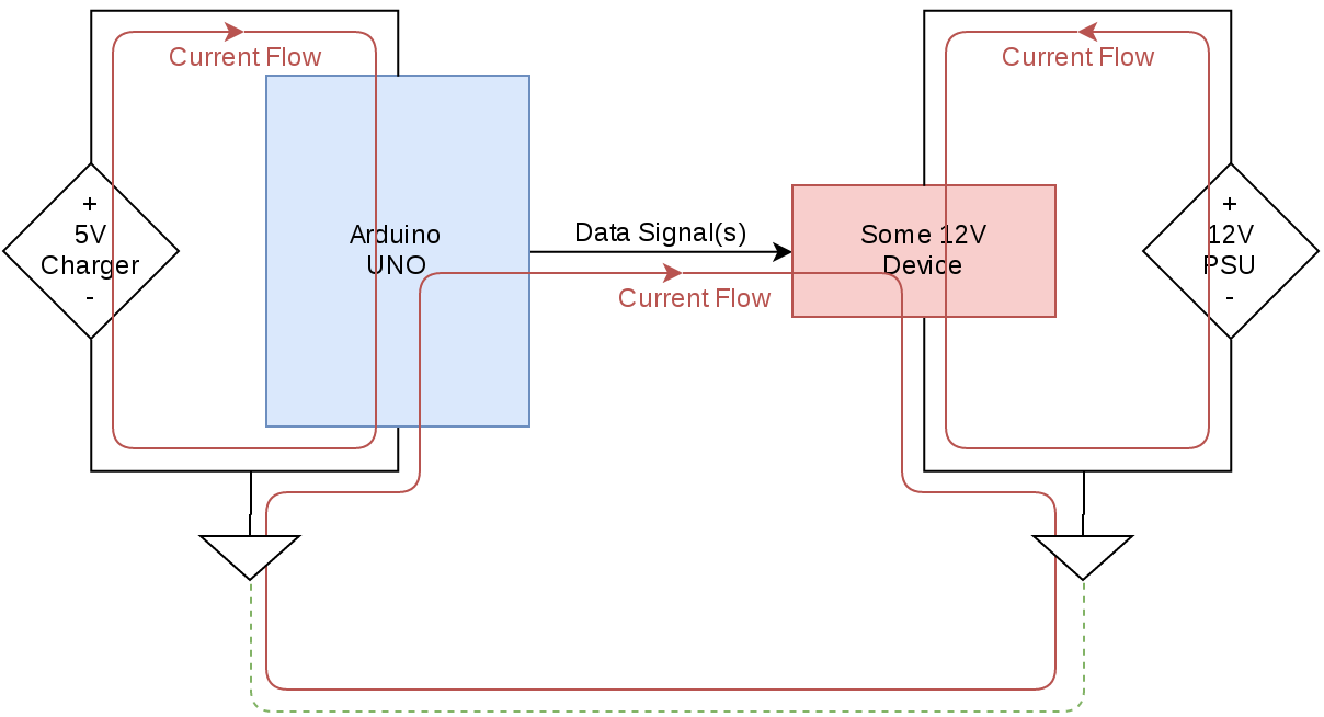
Due to Wordpress’s abysmal handling of code blocks this blog post is now hosted at A lot of the time on the Arduino forums we get questions regarding wiring things together. One common format…
haha
north kelp
@honest nimbus I've used Arduino IDE with success on pi 3.
 ivory fulcrum
is there a way that i could hook my arduino up to my TV somehow and program it like a TFT?
honest nimbus
Look into the TVout Arduino library. With just a few resistors you can generate a composite video signal. https://playground.arduino.cc/Main/TVout/
Composite isn't very high quality, but it's the best you'll get out of an 8-bit micro and without external video processing
And that said, black and white composite can be pretty sharp
If your TV has a VGA input, you can use that as well with just a few more resistors
VGA will be a bit difficult though. Like with first-generation 8-bit personal computers, most of the processor time is going to be spent generating the video signal
Any compute you want to do will have to be crammed into the blanking intervals
More common with VGA is to have one Arduino be a pure video controller and use a second one to run TinyBASIC or otherwise handle the code you want to output

Instructables
Arduino Basic PC With VGA Output: In my previous Instructable I have shown how to build a retro 8-bit computer running BASIC, by means of two Arduino, and with an output signal in B&W for a TV screen. Now I will show how to build the same computer, but with the output signal i...
cyan jasper
can I supply atmega328p with 3V (button lithium cell) and use 5v UART?
north kelp
@cyan jasper There's some discussion of running an atmega328p from coin cells here:
https://electronics.stackexchange.com/questions/87700/how-do-i-power-a-atmega328-with-a-coin-cell-battery

Electrical Engineering Stack Exchange
Ok, so i am really keen to try replicate this project here
I'm still a noob and my knowledge of electronics stretch as far as making a light blink using an Arduino (Maybe a bit more).
I was think...
north kelp
Coin cells aren't designed for heavy draw, so I'd personally consider a small LiIon/LiPo battery instead.
Like one of these:
https://www.adafruit.com/category/574
Adafruit Industries, Unique & fun DIY electronics and kits : Batteries - Tools Gift Certificates Arduino Cables Sensors LEDs Books Breakout Boards Power EL Wire/Tape/Panel Components & Parts LCDs & Displays Wearables Prototyping Raspberry Pi Wireless Young Engineers 3D printi...
cyan jasper
there wont be heavy draw
I just need to know if I damage with 5v uart when I power with lower voltage
It's mostly in sleep condition
north kelp
I don't know if 328p GPIO pins are 5V tolerant when operating at 3V, so I'd also consider a level shifter.
cyan jasper
baah voltage divider it is
north kelp
I've used this, which in addition to being powered by a coin cell, is tiny, fast, and includes Bluetooth LE.
https://www.adafruit.com/product/3372

The Espruino Puck.js is a low energy Bluetooth smart button that can be programmed and debugged wirelessly with JavaScript. It is both multi-functional and easy to use, with a custom ...
cyan jasper
that's way over price range
north kelp
What are you making?
north kelp
What's it logging?
cyan jasper
temperature
north kelp
@cyan jasper Cool. That reminds me, @topaz ferry recently published a really in-depth, 8-episode series on power optimization of microcontroller projects:

This video discusses project design power optimization to maximize battery life. Using a Digilent Analog Discovery 2, Shawn Hymel demonstrates the step by st...
cyan jasper
does it have deep sleep currents?
north kelp
Yep – I'm pretty sure he covers that.
cyan jasper
I couldn't find it anywhere expect a random electronics stack exchange
and it send me to old forum post
awesome!
pine bramble
noob question - if I power a shift register from the 5V pin and have all 8 outputs of the shifter register power LED's then will the power from the LED's be drawn from the 5V pin? If not then it must come from the data/clock/latch pins via the arduino digital out pins which can only supply max 40milliamps and it will die? 🤔
north kelp
The 328P has been around for a decade, so there's probably a lot of interesting stuff in old dusty forum posts.
solar sail
@pine bramble Yes, outputs should be driven with current sourced from 5V or sunk to the ground pin
slender spruce
I am working on a GUI for a project and im using a TFT touchscreen. I had it working fine with a few images but now that im trying to load more in it seems to be having a sook and creating odd graphical loading images. Could i be exceeding the amount of memory
north kelp
That's a good guess, if you're using an Arduino UNO, as it appears.
slender spruce
Using a Mega
north kelp
Or Mega.
slender spruce
Would there be a more suitable Arduino to use?
Or should i look at storing the images on SD card and loading them from there?
north kelp
That would be a great first step.
slender spruce
Guess i need to go buy a SD card then 😛
north kelp
Have you looked at the Grand Central?

Are you ready? Really ready? Cause here comes the Adafruit Grand Central featuring the Microchip ATSAMD51. This dev board is so big, it's not named after a Metro train, it's a whole ...
The Mega has 8K of RAM. The Grand Central has 256K of RAM.
slender spruce
No I havent explored outside of my Mega yet
north kelp
Note that the Grand Central is 3.3V, so I'd be sure to check compatibility with shields based on the older 5V standard.
slender spruce
Hmm the screen seems to be 5v 😦
north kelp
Less expensive would be the Metro M0 Express, with 32K of RAM:
https://www.adafruit.com/product/3505

Metro is our series of microcontroller boards for use with the Arduino IDE. This new Metro M0 Express board looks a whole lot like our original Metro 328, but with a huge upgrade. ...
Do you have a link to that specific screen?
slender spruce
320x240 Colour TFT-LCD Display Shield with Touch for Arduino
Id rather not be twiddling my thumbs waiting for a new board to arrived via shipping. not that i know how long itd take
north kelp
Yeah, guess it's a good opportunity to optimize for the Mega you have.
slender spruce
Is there any advice on how to find a library for interfacing with the SD card on my particular shield?
One complaint with this screen is the lack of direction for configuring it
slender spruce
? I linked that above already 😛
north kelp
Ooops! Fixed the link above.
slender spruce

GitHub
MCUFRIEND_kbv Library for Uno 2.4, 2.8, 3.5, 3.6, 3.95 inch mcufriend Shields - prenticedavid/MCUFRIEND_kbv
This is the library
north kelp
OK, try the examples:
showBMP_kbv_Uno
showBMP_not_Uno
Well, at least you now have examples that run with your imaginary SD card. 😄
north kelp
That's what I'd do.
You're clearly motivated to solve it, and there's an SD card nearby! You can always reformat it when you're done, and put it back. Unless there's special software on the SD card that the dashcam needs.
slender spruce
haha. Ill just buy one on the way home tonight
north kelp
How about just reducing the number of displayed graphics, instead?
slender spruce
well the thing is i didnt even change the number of displayed graphics
just increased the amount loaded in
slender spruce
extern unsigned short mitresaw2[];
north kelp
Have you used PROGMEM before?
slender spruce
I only started Arduino two days ago 😛
slender spruce
yes #include <avr/pgmspace.h>