#help-with-arduino
1 messages · Page 38 of 1
 barren scaffold
 harsh wedge
Laser cutter and other makerspace equip uses the printer interface to receive jobs
So it might be able to work via cups
But yeah not ideal as it's another system for me to maintain 😅
barren scaffold
If cups queueing is a possibility, you can make a front-end queue with auto-hold, and define which computers can touch the web interface to release jobs to the real device. I've had that running on a large-format printer for at least 10 years, maybe 15 at this point.
harsh wedge
Good idea, we'll see what happens! For now I'm going to test this hack upon a hack and see if I can trick this microcontroller
Will report back 🖖
I've got a bunch of octoprint servers to deploy anyways so if it comes to it I'll just deploy a cups server too haha
Thanks for the idea
 north kelp
The part that smells bad to me is putting a mechanical switch on an digital i/o. Yeah, USB is supposedly plug-and-play, but this approach feels brittle.
It's analogous to plugging/unplugging a speaker while the volume is up, in my mind.
 north stream
That's why the USB switch board is being used instead of a simple relay
harsh wedge
Well if it doesn't work we can just unplug it and we're back to where we are now lol. If the cups server went down though there might be more to do on software to fix it. I've been using a similar switch manually for a couple months daily with no issues.
Yeah my end goal is to design a circuit to do this directly. And then I'd need to ensure I'm doing things properly. In general this is kind of complicated but it should work
north kelp
So I could use a nice, optoelectronically isolated solid-state switch in a pretty cabinet, instead of a relay. Hmm.
 humble anchor
The Serial.available function needed for the 32-bit boards?
https://www.arduino.cc/reference/en/language/functions/communication/serial/available/
The Arduino programming language Reference, organized into Functions, Variable and Constant, and Structure keywords.
north kelp
Any reason you don't want to use Serial.available(), @humble anchor ?
humble anchor
@north kelp Hmm nevermind, I now understand the function of it
 cursive knot
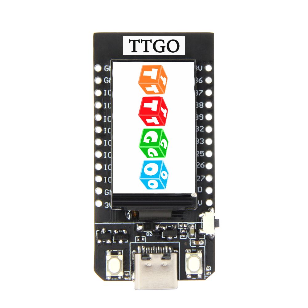
hi all, so i've recently received an esp32 arduino i bought during a flash sale on aliexpress, and im having trouble getting the tft_espi lib to work with it
https://www.aliexpress.com/item/33048962331.html?spm=a2g0s.9042311.0.0.17164c4dbbJh63 purchased from here
points to using https://github.com/Xinyuan-LilyGO/TTGO-T-Display?spm=a2g0o.detail.1000023.9.796d9ca74TE8x9 config here to interface with the display, and despite following the instructions it seems to still not do anything -- anyone have any ideas?
aliexpress.com
Smarter Shopping, Better Living! Aliexpress.com

GitHub
Contribute to Xinyuan-LilyGO/TTGO-T-Display development by creating an account on GitHub.
north kelp
What happens when you run the sample code in the TTGO-T-Display library, @cursive knot ?
cursive knot
/home/nurse/TTGO-T-Display/TTGO-T-Display.ino: In function 'void button_init()':
TTGO-T-Display:50:30: error: no matching function for call to 'Button2::Button2()'
     pBtns = new Button2 [args];

                              ^
In file included from /home/nurse/TTGO-T-Display/TTGO-T-Display.ino:5:0:
/home/nurse/Arduino/libraries/LennartHennigs-Button2-4105e70/src/Button2.h:55:5: note: candidate: Button2::Button2(byte, byte, unsigned int)
     Button2(byte attachTo, byte buttonMode = INPUT_PULLUP, unsigned int debounceTimeout = DEBOUNCE_MS);
     ^
/home/nurse/Arduino/libraries/LennartHennigs-Button2-4105e70/src/Button2.h:55:5: note:   candidate expects 3 arguments, 0 provided
/home/nurse/Arduino/libraries/LennartHennigs-Button2-4105e70/src/Button2.h:29:7: note: candidate: constexpr Button2::Button2(const Button2&)
 class Button2 {
       ^
/home/nurse/Arduino/libraries/LennartHennigs-Button2-4105e70/src/Button2.h:29:7: note:   candidate expects 1 argument, 0 provided
/home/nurse/Arduino/libraries/LennartHennigs-Button2-4105e70/src/Button2.h:29:7: note: candidate: constexpr Button2::Button2(Button2&&)
/home/nurse/Arduino/libraries/LennartHennigs-Button2-4105e70/src/Button2.h:29:7: note:   candidate expects 1 argument, 0 provided
/home/nurse/TTGO-T-Display/TTGO-T-Display.ino: In lambda function:
TTGO-T-Display:62:26: error: 'TFT_DISPOFF' was not declared in this scope
         tft.writecommand(TFT_DISPOFF);

                          ^
TTGO-T-Display:63:26: error: 'TFT_SLPIN' was not declared in this scope
         tft.writecommand(TFT_SLPIN);

                          ^
Multiple libraries were found for "TFT_eSPI.h"
 Used: /home/nurse/Arduino/libraries/TFT_eSPI
 Not used: /opt/arduino-1.8.9/libraries/TFT_eSPI
Multiple libraries were found for "WiFi.h"
 Used: /home/nurse/.arduino15/packages/esp32/hardware/esp32/1.0.2/libraries/WiFi
 Not used: /opt/arduino-1.8.9/libraries/WiFi
exit status 1
no matching function for call to 'Button2::Button2()'
appears to complain about Button2
which is installed
removing all the button stuff and it does seem to power on now
OH
TFT_eSPI tft = TFT_eSPI(135, 240); // Invoke custom library
north kelp
new Button2 [args]; doesn't look like a proper constructor.
north kelp
Sample code should hopefully work. At least it should compile.
Maybe file an issue at https://github.com/Xinyuan-LilyGO/TTGO-T-Display
I'd expect at least parentheses around [args].
cursive knot
hmm, trying to intiailize the library with that doesn't seem to work but whatever they did in that project made it power on
i'll give it some closer reading and file an issue if i can't get it working
north kelp
Also, Arduino tends not to use new.
cursive knot
memory inefficient?
north kelp
We tend to do things like Button powerButton(6);, which creates an instance of Button called powerButton, on pin 6 in this hypothetical constructor example.
cursive knot
so it appears theres a manual control for the backlight pin
north kelp
I think that line is trying to create an array of Button2 objects. I'd comment it out.
Secondly, I'd try changing this line:
Button2 *pBtns = nullptr;
to
Button2 pBtns[2];
TTGO-T-Display:25:16: error: no matching function for call to 'Button2::Button2()' Button2 pBtns[4]; @north kelp
seems to still spew errors,
cursive knot
yes, ive tried with just two buttons as well
just set it to four as kind of a desperate prod to get it to do something
north kelp
Maybe simplify the sketch so that it doesn't store the buttons in an array of pBtns
Just use a separate variable for each button.
Is the board an ESP32 and an ST7789V display?
cursive knot
check the above
its a nonstandard display
has you import a custom profile of sorts f or the tft espi lib
 urban robin
hello
cursive knot
i'd have gotten a proper one with standard hardware but the flash sale for $1/free shipping wasn't a bad idea, wanted to see if i could get a dollars worth out of it
north kelp
Hmmm. I'd file an issue on the sample code you've been provided, and in the meantime, poke around to find other ESP32+ST7789V libraries/examples.
cursive knot
i wouldnt mind just ordering one that's a known model and have less headcahes
north kelp
I'm sure you can get a dollar's worth out of it, with some effort.
cursive knot
any suggestions for ones with included lcds in the mean time?
north kelp

GitHub
Full featured TFT library for ESP32 with demo application - loboris/ESP32_TFT_library

GitHub
ST7789V TFT Driver for ESP32. Contribute to REVOtic/TFTDriver development by creating an account on GitHub.

GitHub
GitHub is where people build software. More than 36 million people use GitHub to discover, fork, and contribute to over 100 million projects.
urban robin
i just got here and i have some questions for the project I've been working on
north kelp
Welcome, @urban robin
urban robin
thx
I've been working this project for a while and i'm kinda stuck
can you help me out with this
north kelp
That's what we're here for.
north kelp
Cool. What's an issue you're dealing with?
harsh wedge
@north kelp @north stream @barren scaffold so I ended up not being able to use the trick I found, but my friend told me he was able to get it working using itself, as long as it's mapped properly. So this effectively tricks the switch into thinking there are two devices plugged in and allows me to have one device plugged in and effectively switch it on/off. Thanks again for the ideas 😄
urban robin
ok so the first problem is that i have been trying to find a way to pause the program when a certain gesture is made and resume when the same gesture is made
but not matter what i try i cant seem to get the desired result
north kelp
How are you detecting gestures? Bend sensors?
urban robin
ya
north kelp
What do you want to have happen when the program isn't paused?
urban robin
i made a number of different gestures that execute certain commands when do
meant to say done
north kelp
Instead of pausing, I'd just have the gesture change the state of a variable. That way the program can continue running, which it has to in order to detect gestures.
urban robin
what do you mean
north kelp
something like:
if (gesture1) {
  if (paused == TRUE) {
    paused = FALSE;
  } else {
    paused = TRUE;
  }
}
then later,
// check if we're not paused
if (!paused) {
  blinkMyLED();
}
oh ok thx
north kelp
Have you run the tutorial at:
https://learn.adafruit.com/force-sensitive-resistor-fsr

That one is for force-sensitive resistors, but it also applies to bend/flex sensors.
urban robin
oh ya i actual have one of those
urban robin
i was trying to make the pressure sensor into a kind of on/off button
for the glove i mean
like stop the voidloop when done
sorry meant to say when pressed
north kelp
The void() loop never stops.
Instead, I would use something like a paused variable inside that loop, as I showed above.
urban robin
ya ok
north kelp
Up at the top of the code, I'd declare a global variable, paused:
bool paused = FALSE;
this right suppose to be inside void setupright
north kelp
Then, each time through the loop, I'd look at paused, and if it's TRUE, I'd do nothing.
north kelp
Actually, that variable declaration would be before setup().
urban robin
ok cool
north kelp
That way, it's global, and available inside any of your functions.
urban robin
i do have one other question though
north kelp
Go on. Yes?
urban robin
ive been trying to make this glove Bluetooth for the longest but no dice
north kelp
What device do you want to pair it with?
urban robin
my pc
north kelp
Which BLE board are you using?
north kelp
Which bluetooth module are you using, then?
north kelp
I don't know how to get a Classic Bluetooth device, like the HC-05, to talk to a PC.
urban robin
what module would you recommend
north kelp
I'd search the https://learn.adafruit.com for Bluefruit for example projects and boards.
Specifically, you'll want Bluetooth LE modules for the most cross-platform compatibility (iOS, Android, Mac, PC).
I've only connected my Bluefruit LE projects to an iPhone.
urban robin
ok thank you
north kelp
Does your PC support Bluetooth LE?
north kelp
Yes.
north kelp

The Adafruit Feather nRF52840 Express is the new Feather family member with Bluetooth Low Energy and native USB support featuring the nRF52840! It's our take on an ...
That board is all in one: Arduino compatible, with built-in Bluetooth LE.
north kelp
It's also got about 100x the RAM of an Arduino Pro Micro.
urban robin
can it send keyboard comands because ive run into that problem in the past
north kelp
You also may need this for your PC, if your PC doesn't have native Bluetooth LE:
https://www.adafruit.com/product/2269

Interested in learning how Bluetooth Low Energy works down to the packet level? Debugging your own BLE hardware, and trying to spot where something is going wrong? Or maybe you're ...
This project demonstrates sending keys to an iPad:
https://learn.adafruit.com/atarifruit-2600-joystick/overview

Adafruit Learning System
Turn a classic Atari joystick into a wireless controller with the Feather nRF52 Bluetooth!
north kelp
Some PCs don't have built-in Bluetooth LE support.
urban robin
dont worry i already have one
north kelp
Cool.
cursive knot
@north kelp got it working :) turns out i actually had a duplicate library installed, of all things that could have been going wrong
urban robin
thanks so much you solve every problem i had
north kelp
@urban robin One thing I suggest all the time is to try to get each component working separately, with separate Arduino sketches, before you build one big project.
urban robin
thx i will
 sinful saffron
Think I might have run into a problem with the Capacitive Touchscreen library https://www.adafruit.com/product/1947 . I had it working with code running on the UNO without issue. I then moved to the YUN, which required me to jumper the 3 pads and cut the other 3 pads for SPI/ICSP. The display works correctly when just the display is connected to the YUN (with no additional connections). When I add an input to a digital pin (beam break sensor) the program fails to run (still uploads). As soon as I remove the beam break sensor inputs, it runs correctly. It also works if I don't include ts.begin(); . I had the beam break sensors on pins 2 and 3.

Add some sizzle to your Arduino project with a beautiful large touchscreen display shield with built in microSD card connection and a capacitive touchscreen. This TFT display is big ...
north kelp
@sinful saffron Are you using a digital pin that isn't otherwise used by the shield? I'd check the schematic of the shield; specifically the capacitive version, to figure out which pins are available for your break beam sensor:
https://learn.adafruit.com/adafruit-2-8-tft-touch-shield-v2/downloads

Adafruit Learning System
Spice up your Arduino project with a beautiful large touchscreen display shield with built in microSD card connection.
Can you make the break beam sensor work on the Yun without the touchscreen shield?
sinful saffron
yeah, the beam break sensors work as long as I only do tft.begin() and not additionally ts.begin()
The display uses digital pins 13-9. Touchscreen controller requires I2C pins SDA and SCL. microSD pin requires digital #4. That means you can use digital pins 2, 3, 5, 6, 7, 8 and analog 0-5. Pin 4 is available if not using the microSD
I had it fully working on the UNO also (before having to cut and solder the 3 pads)
 indigo apex
Can someone please assist me in SQW alarms for the DS3231? (oeserle helped me start it the other day, but i have a few questions)
north stream
I think SQW is the square wave output but the pin might double duty as the alarm output
 simple horizon
How many i2c devices can I have on 1 board
 burnt island
in theory 127 per bus. Realistically much less because of address conflicts and eventually noise from all of the wiring. Some boards can drive multiple busses.
humble anchor
If you want to have a bunch of devices with the same address you can use something like this:
https://learn.adafruit.com/adafruit-tca9548a-1-to-8-i2c-multiplexer-breakout @simple horizon

Adafruit Learning System
I2C addresses collisions? No prob!
Not technically what you asked for but it might be interesting to know!
indigo apex
@north stream regarding how to code it :)
north stream
It's basically a matter of writing numbers in registers to set the alarm time and enable it.
simple horizon
I want to have a trinket m0 have 3 i2c "slaves" and 1 uart
Is that possible?
They shouldn't have the same addresses
indigo apex
@north stream im looking for an example.
north stream
I'm on my phone right now so I don't have any examples hand but can answer questions
I'm guessing you can have an i2c bus and a part. May have to use soft i2c
 carmine sun
Does any one know anything about VL53L0X Time of Flight sensors?
These guys https://www.adafruit.com/product/3317
The VL53L0X is a Time of Flight distance sensor like no other you've used! The sensor contains a very tiny invisible laser source, and a matching sensor. The VL53L0X can detect ...
I'm using them in a test lab setup and I'm getting weirdly inaccurate readings. I have 3 sensors, an lcd, and the adafruit data logging shield plugged into an arduino mega. I've ruled out the sensors interacting with each other and I'm shining them on a piece of reflective tape as the manufacturer recommends idk what's causing them to be off. I'll post my code if someone wants to see it.
The inaccuracies are no more than 1 inch off but they're supposed to be much much tighter than that.
north kelp
@carmine sun Can you share a sharp photo of your wiring?
How are you setting the I2C addresses of your sensors?
carmine sun
My wiring isn't terribly pretty in a picture so gimme a sec and I'll make a diagram, as far as addresses go I'm using the method described in the adafruit guide above. With sequence of shutdowns to the appropriate pins and the line " lox.begin(insert address here)
I checked that the adresses are being set correctly with the i2c scanner provided on the arduino website and they were all what I set them to and the data logger and lcd screen were different entirely
30, 31, and 32 are what I set the sensors to be
north kelp
What's the range of distance you're aiming at?
“My wiring isn't terribly pretty in a picture so…”
I get it, no one's is, but it helps me a lot to diagnose. That and source code.
north kelp
You mention reflective tape. Like mirrored Mylar?
carmine sun
More like the shiney stuff they put on ducting in your house
north kelp
What about aiming at non-shiny, white or gray? That's what I read being tested in the datasheet.
(Also, are you getting reasonable measurements with a single sensor, using the example code?)
carmine sun
I did sheets of printer paper and cardboard boxes
also when I was building it the sample code ran fine but then again I didn't put a ruler up next to it to see
north kelp
You say "weirdly inaccurate"; can you quantify that?
Related issue in the Forums:
https://forums.adafruit.com/viewtopic.php?f=8&t=154212&p=760718&hilit=Adafruit_VL53L0X#p760718
carmine sun
yeah I was expecting that level of variance, mine is more in the range of a half inch or more
(I'm converting to inches in my code by doing mm/25.4)
the other products I'm using are:
https://bit.ly/2IsceN5
https://bit.ly/2KSnmYo

This new Adafruit shield makes it easy to use a 16x2 Character LCD. We really like the Blue & White 16x2 LCDs we stock in the shop. Unfortunately, these LCDs do require quite a few ...

Here's a handy Arduino shield: we've had a lot of people looking for a dedicated and well-designed data logging shield. We worked hard to engineer an inexpensive but well-rounded ...
north kelp
Your code looks decent, and compiles fine.
carmine sun
yeah it works the results just float weridly all over the place
north kelp
If you point a sensor at a surface 100mm away, what readings do you get?
carmine sun
sorry, I work in inches here's the file from placing a static blue notebook in front of all three sensors at about 3inches
all reading slightly different values ranging from 3.1 to 3.7 inches even though they were just resting on the table
that's +/- 13mm ish
are there at least some other strategies I could use to get more accurate data other than smoothing by taking an average reading?
carmine sun
oh, maybe I'm just nuts
north kelp
I am, too!
carmine sun
aren't we all
is there anything I can do to get more accurate data?
in code I mean
north kelp
Checking…
carmine sun
also, super thanks for the help I really appreciate it
north kelp
From the datasheet. High accuracy mode might be an option, if supported by the Adafruit library. But even then, it's +/- 3%, which is +/- 36mm at 1.2m distance, if my calculations are right.
I'd also try turning on the sensor library's debugging, like this, and see if there are any silent errors happening:
if (!lox1.begin(LOX1_ADDRESS, true)) {
But other than that, the variance you're seeing looks within spec for that sensor. What range of accuracy would you be happy with, @carmine sun ?
 crystal mesa
Is this a case where you need to take the average of multiple readings?
carmine sun
Sorry I had to drive somewhere @north kelp I'll definitely try that when I get back to my set up tomorrow, I'd like to get an accuracy of around 2.5mm or 0.1 inches
and yes, I already take an average of 10 readings taken at 1 ms intervals and averaged for each sensor
crystal mesa
I figured, you seem pretty on top of it, but I know I've overlooked "obvious" stuff before so I figured it didn't hurt to ask
at the very least someone else reading along might realize "oh, hey, that's a thing to do with sensors"
carmine sun
no problem, thanks for checking, every little bit helps
harsh wedge
Hey guys, I need some guidance on reading a GPIO pin from a high voltage source
This is the device whose relay (specifically relais 2) will be opening or keeping closed a relay which I plan to read on an Arduino
the "maximum rating" for said relay is 250v at 10a, but the Arduino GPIO probably won't be able to interpret this signal directly. How can I ensure I can read this on the Arduino's GPIO pin safely?
 fleet pewter
There's probably a more efficient way, but the solution that immediately comes to mind is a simple voltage divider circuit to scale it down
fleet pewter
If nothing else it lets you move on with prototyping with parts you probably already have, while you're searching out the optimal solution
 harsh wedge
good to know! can you tell I'm new to electronics?
fleet pewter
Try our easy to use Voltage Divider Calculator. Enter any three known values and press Calculate to solve for the other.
harsh wedge
Also with a big voltage like this is it possible to use just one of these circuits?
fleet pewter
No biggie!
I honestly don't know how well voltage dividers scale, but I assume the resistor will go poof in a dramatic way if it does. Please don't take my word on high voltage safety, though
harsh wedge
cool stuff, should be simple enough. I'll just measure the voltage with a multimeter and plug the numbers in here 😄
lol yeah just some smoke probably
I'll test before plugging into the arduino lol
fleet pewter
This looks relevant lhttps://www.evilmadscientist.com/2012/basics-power-dissipation-and-electronic-components/
Tbh half of expertise these days is knowing just enough to figure out the right Google keywords. Don't feel bad, you'll get there someday too!
We love teaching here
And even if a voltage divider doesn't turn out to be the right tool for this job, it will teach you a few very important things that are vital for many projects
harsh wedge
awesome! yeah I had a question here earlier this week about another part of this project
sweeeeeet 😄
got a lot of good ideas
lol
hoping to get a good grasp on electronics soon enough. everything with it seems like logic puzzles
fleet pewter
Ohm's Law is super important in general, so playing with voltage dividers will be educational
I mean, you're not wrong?
The scope of the puzzles just gets bigger
harsh wedge
yeah currently I'm pretty boggled when I see schematics
fleet pewter
Ok I gotta go to bed, but I hope this gives you a place to start! The experts on here will probably give you some better guidelines on working with mains power when they see this convo
harsh wedge
thanks for the power dissipation article btw! seems perfect for me.
cool cool! have a good night
fleet pewter
Glad it helped!
 frank linden
One other thing, I'd recommend using an opto-isolator (https://en.wikipedia.org/wiki/Opto-isolator) just to be safe, you could feed the voltage divider output into the opto-isolator and then read the output of that.
harsh wedge
Good idea! I learned a lot from this. One thing I was wondering for when I initially measure the relay's output voltage is if most multimeters can handle 1000V or 1kV? Then after I measure I can just get a component rated for the initial output voltage.
fleet pewter
uhhh... aren't you working with mains power? I assumed you'd be under like 250 volts or somtehing
I'm scared of working with 1kV and you probably should be too
that said, your multimeter should be able to tell you... and I suspect multimeters are rated for mains power. your multimeter should tell you what its limits are, either in the manual or if you google it
your multimeter probably also has different modes for different voltage ranges - if your meter can switch into a range that's above the voltage you expect, you'll be good

oh, you actually want the range with the wiggly line if you're working with AC power, not the solid + dotted line
your multmeter should have both
harsh wedge
gotcha, thanks!
sinful saffron
Anyone know why I would be getting such a wide range of values on an analog read from a beam break sensor that is set for high and not changing?
#define beambreakin A3
const int beambreakinled = 4;
int beambreakinstate;
#include <Bridge.h>
#include <BridgeServer.h>
#include <BridgeClient.h>
void setup() {
Bridge.begin();
pinMode(beambreakinled, OUTPUT);
pinMode(beambreakin, INPUT);
digitalWrite(beambreakinled, HIGH);
}
void loop() {
beambreakinstate = analogRead(beambreakin);
Console.println(beambreakinstate);
delay(100);
}
getting 0 all the way up to around 1023
harsh wedge
not sure if this is the correct answer, but one thing I needed to do when I was getting a range of values was to ensure there's a resistor to pull up any voltage between reads.
so whichever pin you're reading from should have a resistor there to take care of any remaining voltage that would otherwise change the output of your read
sinful saffron
Thanks for the help, I've been moving pins all around and didn't even think to check that (was previously working on digital pins but had to move some to analog pins since I ran out hah).
harsh wedge
so I'm in America and haven't found any octocouplers/isolators that are "110V". If I feed 110V through this 220V one will it still come out as 5V on the other side? I have a general idea of how the isolator works, but I'm not sure in this context what it's doing. https://www.ebay.com/itm/5Pcs-1-Bit-Ac-220V-Optocoupler-Isolation-Module-Testing-Board-Adaptive-For-Plc-h/132711128303?epid=0&hash=item1ee6331cef:g:8Q4AAOSwWe9bUXJX

eBay
Adaptive to PLC 24V level. Functuon:Testing whether AC 220V is existed.
it emits light which is picked up on the other end by a sensor, which in turn sends either 3.3 - 5v or 0v (depending on the design)
not sure how it gets 5v to the other side of the circuit, and also if it does this continuously (e.g. I will be driving this from a relay, while the relay is on will I be able to read 5V on each iteration of my loop() for arduino?
 tribal briar
@sinful saffron the analog pins can be read with digitalRead() or analogRead() as needed 🙂
sinful saffron
for some reason I had to add INPUT_PULLUP on the analog pin but not the digital pin for it to function the same
not a big deal other than having to add it though
frank linden
I'm not 100% sure if it would accept 110V, I've never bought them as a 'package', I usually just pick them up from DigiKey. and since most are designed for DC input, it complicates things slightly. So honestly, I would give that module a try because otherwise you're going to have a little bit more circuit design ahead of you before you get a good clean logic signal.
harsh wedge
Oh I think I'm plugging DC into this. I'll give it a test :)
Not completely sure though! The voltage is coming from another relay. I think first I'll measure what's actually coming from it and then test accordingly
north stream
It says it adapts to 24VDC so it may well work with 110VAC
burnt island
@sinful saffron that makes sense. Originally your input circuit was just floating at whatever stray voltage was induced by the environment, minus a tiny amount sipped off by the reading circuitry. Your beam break sensor is probably just a photo resistor tied to ground in a voltage divider setup. Without the pullup trying to pull the voltage to 5V or 3.3V you won't have a consistent "high" voltage reference to see how much the photoresistor is letting through.
 pine bramble
Any project that can help me learn more about arduino?
harsh wedge
lots of projects here https://learn.adafruit.com/search?q=arduino
instructables is also good
but my best recommendation is to find a project you actually want to make, that you're motivated to make 😄
pine bramble
@harsh wedge thank you very much
tribal briar
@pine bramble, I recently purchased a FunShield. It has been... Fun. It's a great all-in-one shield for playing with code on the Arduino Uno https://www.tindie.com/products/MakersBox/funshield-kit-for-arduino/

Tindie
An educational shield for your Arduino that will let you get started with programming with no messy wiring!
pine bramble
@tribal briar thanks
north stream
How did you set it? Some examples I've seen use the time the code was compiled instead of the current time
simple horizon
Ya it uses the computer time but that time is correct
carmine sun
Hello anyone I have this https://www.adafruit.com/product/1141 shield on my adafruit metro (an uno clone) and I'm running the rtc example sketches and the clock just isn't ticking. It still prints time to the serial output but it never changes
Here's a handy Arduino shield: we've had a lot of people looking for a dedicated and well-designed data logging shield. We worked hard to engineer an inexpensive but well-rounded ...
any ideas why? I have the button battery and SD card inserted
simple horizon
Is the coin cell inserted properly
north stream
Some clock chips have a "start" function that has to be executed to start the clock.
 errant geode
Can someone help me with capacitors? I make something like this and when I connect it to 5v from USB my diode not work. But when I remove capacitors it works good. What can be the problem? This is 2x 2.7v capacitor so it both have 5.4v.
humble anchor
Check the resistance of the capacitors @errant geode.
Also maybe remove the led and resistor. Disconnect the power and measure the voltage on the caps
errant geode
@humble anchor Voaltage is 1.5v. So I must charge this capacitors to 100% to get 5.4v? And why my diode not working with capacitors? Does capacitors "eat" all energy?
humble anchor
They shouldn't, maybe try some other capacitors? @errant geode
Maybe try adding a small resistor between the caps and ground @errant geode
north stream
If the capacitors are hooked up backwards, they'll consume a lot of current (and get damaged in the process).
If your supply doesn't have enough current, it will take a while to charge the capacitors (I'm guessing those are DLC capacitors of some sort, if so they have a significant amount of storage and your USB may be shutting down due to overcurrent).
errant geode
I add 150R resistor and now diode work, wehn i connect power supply. After about 15 seconds voltage changes from 1.56 to 1.64 so i guess i must charge it to about 3v?
 pulsar charm
anyone familiar with bash scripting here?
seems like stack overflow, askubuntu and linux exchange are all down for maintenance at the same time lol
I just tried out arduino-cli and I'm writing a few upload scripts for remotely deploying code to an arduino attached to my pi
 chrome kayak
Anyone available by chance?
pulsar charm
I got my problem sorted out! Thanks! If anyone wants to know more about headless deployment of arduino code I would be happy to share
@chrome kayak what's up?
north kelp
Sounds interesting, @pulsar charm
north stream
@errant geode Sounds like you just needed to limit the current to charge the (large) capacitors.
pulsar charm
yeah we are living in interesting times
platformio just turned open source this month so I really wanted to give a go at doing a proper CI/deploy pipeline for my hobby arduino codes
for anyone wanting to have a go at compiling/uploading your arduino code via CLI, here's the link I found most useful https://itp.nyu.edu/physcomp/resources/using-the-arduino-command-line-interface/
errant geode
@north stream I charged capacitors to about 4v and try again, now the diode works good. And when i connect power supply both capacitors are charging and diode working.
north stream
Nice!
humble anchor
@errant geode good capacitors can pull an insanely high current, the 5V powersupply probably can't handle that and detects a short.
The large current can also lead to a really high voltage spike
north stream
It can lead to a voltage sag, but I'm not sure how it would lead to a spike (usually voltage spikes come from inductors).
humble anchor
A good capacitor has such low impedance that large currents flow, causing 'self-inductance' as they call it
It probably won't happen that much with electrolytic capacitors though
 fierce ridge
What would be a good way to rewrite this bit of my code:
    delay(250);
    digitalWrite(LED_BUILTIN,LOW);
    delay(250);
    digitalWrite(LED_BUILTIN,HIGH);
    delay(250);
    digitalWrite(LED_BUILTIN,LOW);
    delay(250);
    digitalWrite(LED_BUILTIN,HIGH);
    delay(250);
    digitalWrite(LED_BUILTIN,LOW);
digitalWrite(LED_BUILTIN,HIGH);```For context, I am making a built-in LED flash a specific pattern to signify its performing a specific function
 olive carbon
I'm having issues with my nRF52832
`
Bluefruit 52 HW Info
MAC Address: C1:20:D:98:F7:6C
Device ID : E6F3A9D697060ECB
MCU Variant: nRF52832 0x41414530
Memory : Flash = 512 KB, RAM = 64 KB
BSP Library : 0.11.1
Bootloader : s132 6.1.1
Serial No : 25337566193874728406
`
it will not load "StandaerdFirmataBLE"
`
C:\Users\HeX\Documents\Arduino\libraries\Servo\src\nrf52\Servo.cpp: In member function 'void Servo::writeMicroseconds(int)':
C:\Users\HeX\Documents\Arduino\libraries\Servo\src\nrf52\Servo.cpp:92:12: error: 'g_APinDescription' was not declared in this scope
instance=(g_APinDescription[pin].ulPWMChannel & 0xF0)/16;
^~~~~~~~~~~~~~~~~
C:\Users\HeX\Documents\Arduino\libraries\Servo\src\nrf52\Servo.cpp: In member function 'int Servo::readMicroseconds()':
C:\Users\HeX\Documents\Arduino\libraries\Servo\src\nrf52\Servo.cpp:123:12: error: 'g_APinDescription' was not declared in this scope
instance=(g_APinDescription[pin].ulPWMChannel & 0xF0)/16;
^~~~~~~~~~~~~~~~~
Multiple libraries were found for "Servo.h"
Used: C:\Users\HeX\Documents\Arduino\libraries\Servo
Not used: C:\Users\HeX\Documents\ArduinoData\packages\adafruit\hardware\nrf52\0.11.1\libraries\Servo
Not used: C:\Program Files\WindowsApps\ArduinoLLC.ArduinoIDE_1.8.21.0_x86__mdqgnx93n4wtt\libraries\Servo
exit status 1
Error compiling for board Adafruit Bluefruit Feather nRF52832.
`
i deleted the dir it was looking in and copied over adafruit's and now its working
it was just a lib issue dargh i should have read the error
 short wasp
Looking for “adafruit_TFTLCD.h. For a 3.5 TFT shield (demo sketch). Did find some reference on Github but. It’s not clear how to down load it.
Tried the “Manage library” in the IDE but it could not find it in its listing.
humble anchor
@fierce ridge you can use an array and a loop
bool sequenceName[] = { 1, 0 ,1, 0, 1, 0,1};

for (int i = 0; i<=6; i++){
     digitalWrite(LED_BUILTIN, sequenceName[i] );
    delay(250);
}
Just make sure the i<=6 is actually the size of the array -1
short wasp
Update....found and got Adafruit_TFTLCD.h installed. The info header in the sketch says that this library needs to be configured for either the breakout board or the shield. I have the shield model. How do I make those config changes in the h file?
fierce ridge
@humble anchor thank you!
 random burrow
headdesks anyone here good with a USB Host shield 2.0 clone, I'm trying to make a serial echo sketch with an FTDI Serial converter to the USB Host Shield
which means I'm trying to figure out how to read and write to the FTDI device's class
short wasp
Ok.....advanced to being able to edit the h file......now I need to get it moved to the right place in the ide. Not seeing and sub folders in the main Arduino program file tree.
north stream
May have to restart the IDE to find stuff in subfolders.
Let me get this straight: you want to use a USB host shield (clone?) to talk to a USB to serial chip, to implement a serial echo sketch? This seems like going around the block to get next door (there are easier ways to get a serial port), but that probably just means I'm missing something.
random burrow
basically I'm not sure how to get info from and to the device using cdcftdi.h
the device is a mixing console controller for a video switcher, I don't have options to change it's serial output from it's FTDI serial converter
north stream
Ah, you're stuck with the FTDI and you just want to talk to it.
random burrow
I already own the USB Host Shield and a Leonardo
yep
hilariously I'm also using an XBee S2 pair set to AT mode to hook the setup to the switcher as it's the most convenient TTL Serial to USB device I have, and I just want to have my Leonardo set up to monitor the traffic between the control surface and the switcher
north stream
That's a great hack!
random burrow
end result... I want to be able to emulate the control surface to get the status of cameras, standby, online
basically making tally lights for our studio
north stream
Yeah, makes sense, just need to get over some hurdles to manage it.
random burrow
I'm the engineering volunteer at a public access TV station, we're one of the few in my state to have an actual studio
yeah, the big hurdle's just... how do I hook the control surface into the arduino stack in something that'd let me send it's data to Serial1, send Serial1 to it, and have both the USB Host serial and Serial1 sent to Serial so I can log it and work out the protocol
when I'm done working out the protocol, I could probably use any of my serial providing microcontrollers to do the emulation, because if I understand it right, the software just pings all the serial ports for what they are, and listens for handshakes from the control surfaces, even have a playback control for a time to test this before I hook my stack into the actual mixer
all this just so I can add a little light on the cameras to go green when the director's got that camera on the ready, and red when that camera's the one being recorded
north stream
Makes sense. I've been known to use two serial ports to monitor protocol (one for transmit, one for receive) and combine the data for analysis.
random burrow
yeah, just wish I knew how to work with the FTDI libraries
north stream
Alas, I've never used them.
random burrow
no problem, hopefully someone here has worked with it
I think right now the FTDI is getting loopback messages, as when I work with the playback control I'm borrowing lights up when I push certain buttons (this isn't a model for the device I'll be working with, as this is an older design)
kinda wish I could just do a USB redirect to make the setup as I need it, then I could just use the XBees and a computer
humble anchor
@random burrow You can also use a teensy 3.6
with an usb host cable https://www.pjrc.com/store/cable_usb_host_t36.html
At least that is my recommendation over a USB shield
It is not 5V tolerant, that is a major downside
random burrow
I have the current hardware on hand, switching to a teensy would require additional hardware
I do want to upgrade from my 2 Teensy 3.1 boards but that's not in the current budget
hell, I have an Edison, if I could get that working the right way, I'd be fine with using that
hm...
 runic brook
hey, i want to DMA a sequence of bits put of three of my pins and have come tot no avail as to how to make it work. i found this: https://forum.arduino.cc/index.php?topic=347125.0 but whenever i try to use it i get a /Documents/Arduino/sketch_jul31b/sketch_jul31b.ino: In function 'void dma_duty_init()': sketch_jul31b:81:9: error: 'struct Pm' has no member named 'AHBMASK' arudino error. Does anyone know how to do this?
ZERO example: PWM + DMA, timer-capture event + DMA
 agile whale
Hello! I hope someone can help super quick. I have a 8x8 neopixel grid that works with circuitpython but not arduino code on a Feather m4 Express.
Caveat: I have an external 5V supply that works in Circuitpython but not Arduino unless I hook the power of the grid to the USB power out on the feather. Can anyone let me know why?
Wow writing this out gave me an idea. Power supply was outputting 5.5V but USB out on feather was output 5.2V so I switched to an external battery pack to privdes 5.1V and it worked. Thank you for letting me write that out!
agile whale
FYI the patterns being played via circuitpython and arduino weren't the same. The circuitpython code was a rainbow effect and the arduino was a low brightness all white. ws2811's. Bye!
 winter furnace
has anyone messed around with the hardware debugging for 2560 based chips?
I just got a mega, and I'm trying to find the cheapest way to get into the jtag hardware debugging
i thought I was going to be able to do it just with the board and a dream, but I see now that is wrong
humble anchor
@agile whale I didnt even know you could control neopixels with the m4 express. Doesn't it require 5V data input?
@agile whale You did connect the ground of both?
winter furnace
I'm suspicious of something like this since it's 1/10th the cost of everything else https://www.amazon.com/WINGONEER-ATMEGA16A-Emulator-Programmer-Debugger/dp/B0725QJ2KW/ref=sr_1_3?keywords=avr+debugger&qid=1564604319&s=electronics&sr=1-3
humble anchor
@winter furnace maybe it is just an programmer not really a debugger
winter furnace
I was hoping I could find a way to use another arduino or an stm32 or something as the jtag debugger, but I'm not turning much up
humble anchor
@winter furnace Like this? https://hackaday.com/2018/02/07/debugging-an-arduino-with-an-arduino/
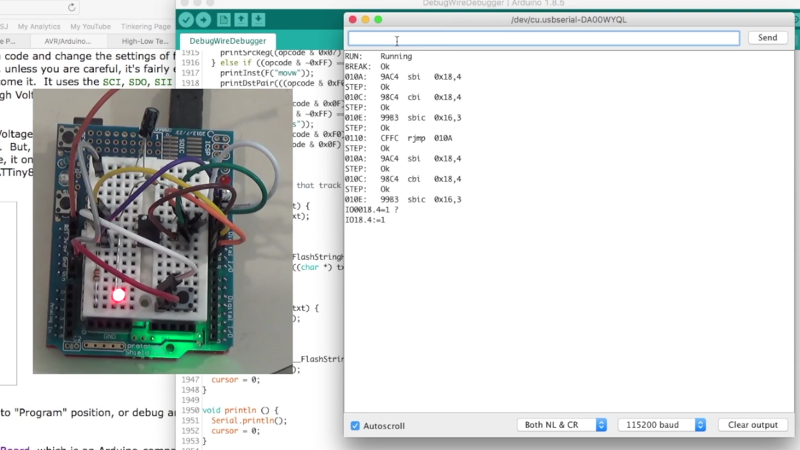
As every Hackaday reader knows, and tells us at every opportunity in the comments, adding an Arduino to your project instantly makes it twice as cool. But what if, in the course of adding an Arduin…
winter furnace
yeah, but the actual jtag on chip debugging on the 2560 and not the 328's debugwire
i messed around with that a bit, but it was very limited
i'd like for it to work with atmel studio or whatever
humble anchor
Have you tried a FT2232 board?
winter furnace
I have one I had originally bought to go with this mega for debugging, but now I can't remember what exactly I was going to do with it
humble anchor
Hmm that won't work with atmel studio
winter furnace
originally I had thought I could use the FT232 to pull off the debug data from the JTAG, but now I look into it more I realize it's going to need something to process it as it comes off the chip
it is not quite as simple as I had hoped
humble anchor
The FT2232 is way more advanced than the FT232
winter furnace
ah, then no. I only have the 232
humble anchor
From the datasheet: "Multi-Protocol Synchronous Serial Engine (MPSSE) to simplify synchronous serial protocol (USB to JTAG, USB to I2C,USB to SPI) design."
winter furnace
hmm, and like $15 from amazon
thank you for the lead!
I'll have a look into this one
winter furnace
oh, really?
like the altera ones?
the only thing that's stopped me from buying one to mess around with is the altera programming cable is like $130
I've always wanted to mess around with one
sounding better and better
humble anchor
Altera? Those are really cheap, maybe not for the really expensive ones
You even have the arduino mkr vidor 4000
winter furnace
I see them for sale for like $5 occasionally https://www.banggood.com/ALTERA-FPGA-CycloneII-EP2C5T144-Minimum-System-Board-Development-Board-p-1223888.html?rmmds=search&cur_warehouse=CN

www.banggood.com
Online Shopping at Banggood.com!
but the altera usb blaster is hard to come by
humble anchor

eBay
altera Mini Usb Blaster Cable For CPLD FPGA NIOS JTAG Altera Programmer | Professioneel materiaal, Elektrische uitrusting, accessoires, Elektronische componenten | eBay!
Inside is something like an stm32F1
winter furnace
could the ft2232 theoretically do the job though?
oh, bummer. the one I was looking at on amazon was not actually a FT2232
humble anchor
I can't find it for altera
Maybe try FT2232D

www.banggood.com
Online Shopping at Banggood.com!
winter furnace
yeah that is the one I am eyeing now
trying to find one with prime shipping on amazon :p
that one sounds pretty promising
humble anchor
If have used that one on their Lichee Tang, FPGA development board
Uses a really weird FPGA brand. Anlogic
They dont have a english webpage yet kind of weird
winter furnace
can any of the 232 variants handle jtag?
the only one I see on amazon that says it is this: https://www.amazon.com/KOOBOOK-FT232H-High-Speed-Multifunction-Module/dp/B07T9CPMHT/ref=sr_1_9?keywords=usb+jtag&qid=1564608129&refinements=p_85%3A2470955011&rnid=2470954011&rps=1&s=gateway&sr=8-9
hmm, adafruit mentions it too
hmm, looks like the 232H is a variant of the 2232
humble anchor
@winter furnace https://electronics.stackexchange.com/questions/56127/is-the-ft232h-a-single-channel-version-of-the-ft2232h

Electrical Engineering Stack Exchange
I'm looking at the Opendous JTAG Project, and would like to integrate a this JTAG debugger circuit on my ARM Cortex M3 experiment board I'm designing.
I noticed that Channel B, on the FT2232H chip...
Seems like you are right, adafruit even sells one
winter furnace
this is close, and uses the chip
but doesn't mention debugging
seems like it will work with openocd, but I'm not quite sure if that will integrate with atmel studio
humble anchor
Companies like that usually don't support other devices like that
winter furnace
i was hoping openocd offered some kind of compatibility layer that would work with visual micro or something, but I'm not exactly clear on what it is
random burrow
I found the library's documentation! https://felis.github.io/USB_Host_Shield_2.0/class_f_t_d_i.html now if I understood half of it
winter furnace
I think it will, since it works with gdb
alright, I am going to go for it
alright, I purchased the adafruit breakout from amazon
should be here friday
the other one was $5 cheaper but had 3 day shipping instead of 2 😂
I'll let you know how far I get with it
humble anchor
@winter furnace Ok great!
winter furnace
hmm, the more I look at other 232H based usb->jtag adapters though, the more it looks like they have a bunch of other parts as well
this mentions openocd, but is short on specifics
winter furnace
i cancelled it; not totally sure it's gonna work for me

GitHub
In application debugger for ARM Cortex microcontrollers. - blacksphere/blackmagic
this project looks interesting; I think I'm going to explore it first
seems like it might be able to run on my stm32
this actually looks perfect
blog
source for my blog (** view at https://satoshinm.github.io/blog/ **)
winter furnace
back to square 1
still not totally sure if I can just use an ft232H directly
it seems like the atmel-ice does a bit more stuff aand interpretation than that would
I'm not sure where exactly the proprietary parts of the protocol are relevant
cheapest I can find the atmel ICE seems to be $90 :/
humble anchor
Why do you want to use an atmega 2560? @winter furnace
carmine sun
Hi, all I'm getting an error and I can't figure out why! The error is "cannot convert 'float*' to 'float' in return. Here's my code:
void calibrateCheck() {
  // creates a boolean to determine if the user wants to run a calibration
  bool pass;
  // prompts the user to calibrate
  lcd.setCursor(0, 1);
  lcd.print(F("Press SELECT to"));
  lcd.setCursor(1, 1);
  lcd.print(F("Calibrate or... "));
  delay(1500);
  lcdClear();
  lcd.setCursor(0, 1);
  lcd.print(F(" Press LEFT to  "));
  lcd.setCursor(1, 1);
  lcd.print(F("Skip Calibration"));
  delay(1500);
  // uses button prompts to determine the user's choice
  for (int i = 0; i = 1; i += i) {
    if (buttons & BUTTON_SELECT) {
      i += 1;
      bool pass = true;
    }
    if (buttons & BUTTON_LEFT) {
      bool pass = false;
      i += 1;
    }
  }
  if (pass) {
    lcdClear();
    lcd.print(F("New Calibration "));
    delay(1000);
    float offsets = calibrations();
    return offsets;
  }
  else {
    lcdClear();
    lcd.print(F("Uncalibrated Run"));
    delay(1000);
  }
}
 float calibrations() {
  // set number of distances to calibrate at
  int caliPoints = 3;
  // create variables for calibration distance to calibrate at
  float dist1 = 3.00;
  float dist2 = 10.00;
  float dist3 = 18.00;
  float dists[caliPoints] = {dist1, dist2, dist3};
  float offsets[] = {};

  for (int i = 0; i < (caliPoints - 1); i += 1) {
    float caliDist = dists[i];
    lcdClear();
    lcd.setCursor(0, 1);
    lcd.print(F("Place sensors at"));
    lcd.setCursor(1, 1);
    lcd.print(String(dists[i]) + " to surface");
    delay(1500);
    lcdClear();
    lcd.setCursor(0, 1);
    lcd.print(String(dists[i]) + " to surface");
    lcd.setCursor(1, 1);
    lcd.print(F(" Then press UP  "));
    for (int p = 0; p = 1; p += p ) {
      if (buttons & BUTTON_UP) {
        offsets[i] = calibrate(caliDist);
        p += 1;
      }
    }
  }
  return offsets;
}
float calibrate(float calDistance) {
  float offset = 1.0;
  return offset;
} ```What's the proper way to return an array, or is the problem trying to input the float into the calibrate function?
 shadow bronze
one note; after the three back ticks (`) add ino
i.e.
float calibrate(float calDistance) {
  float offset = 1.0;
  return offset;
} ```er not ino, but cpp
carmine sun
okay
shadow bronze
sorry, the first 3
shadow bronze
carmine sun
okay okay
shadow bronze
one thing, you could pass the array in the function and not have to return anything
so
carmine sun
I need to get the offsets to my main code
shadow bronze
void calibrate(float calDistance, float *offset) {
  offset[0] = 1.0;
}
wait what? so that just edits the array with out using return?
shadow bronze
another alternative is to make offset global
yeah
any pointer / array is automatically updated
shadow bronze
np
humble anchor
You can change any global variable inside any function without a return
That's why they are global
O wait nvm
winter furnace
@humble anchor I picked one up because I wanted to be able to use a debugger to debug my arduino projects before I move them to nanos
I had a lot of trouble with reading a serial protocol recently, and it would have helped a ton to have on chip debugging while I was working it out
pulsar charm
is there a serial communication between arduinos
I've recently had to split my code between two unos out of practical concerns and now I'm wondering if there is a way to share some bits of data between them O_O
shadow bronze
well, there's uart and i2c
humble anchor
@winter furnace I know what you mean. I had to debug the signal between a computer and an Arduino.
I used a program that can capture the communication of a COM port
Between what was the serial communication?
Adafruit also says that UART can be flakey
https://learn.adafruit.com/adding-a-wifi-co-processor-to-circuitpython-esp8266-esp32?view=all#esp8266-or-esp32
 winter furnace
it was the signal off of some dro scales. the format on mine was different than anything I found documented
no scope and all I had to go off of was this woefully inadequate raspberry pi logic analyzer
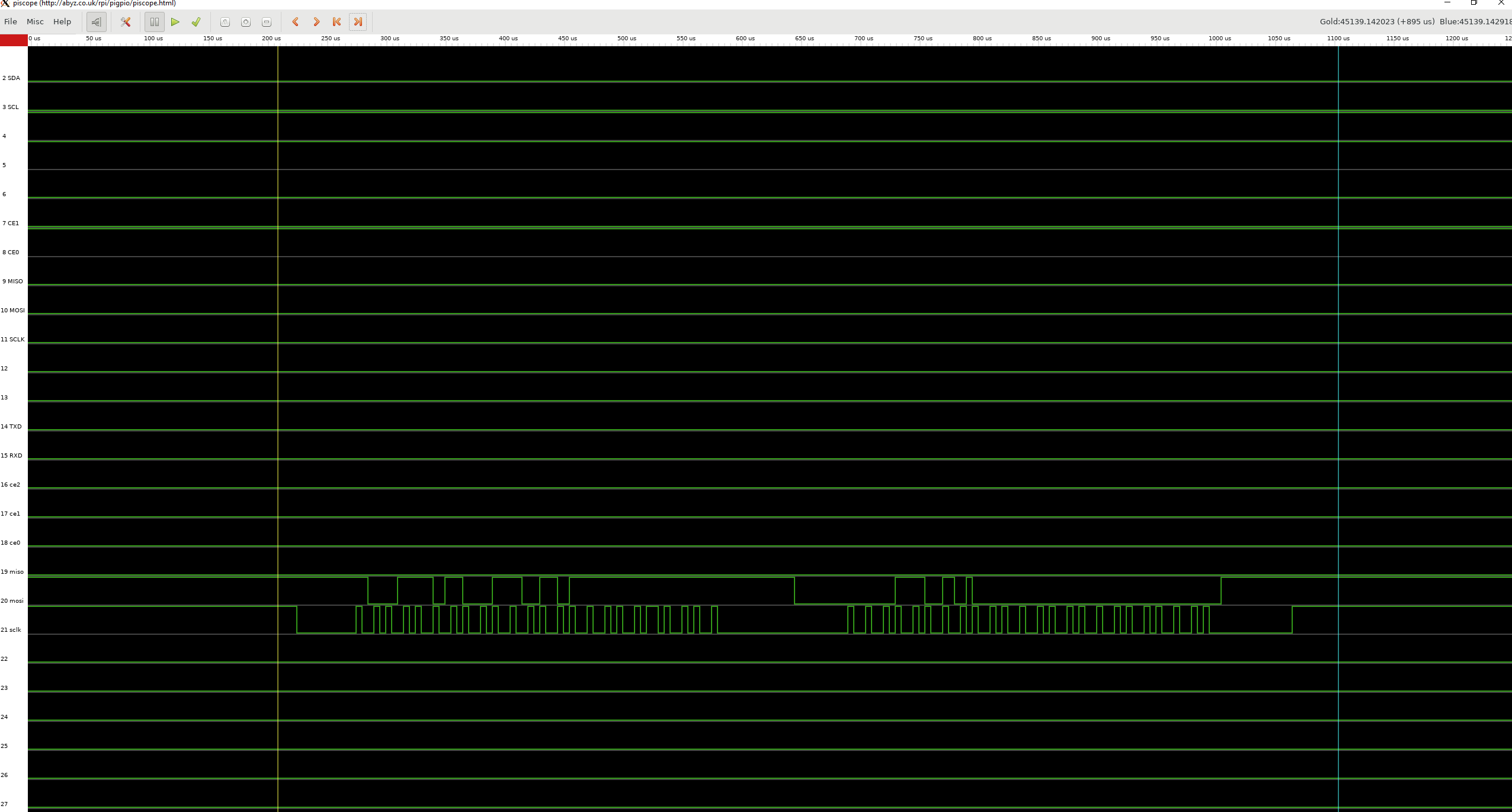

the clock pulses are about 4us long, so it was kind of pushing the timing on the arduino
took me awhile to realize that I couldn't even fit a left shift in when I was reading it because I was missing transitions
the protocol ended up being fairly simple in the end though, just clock and data
the data is 2 23-bit signed integers, and the second one has all its bits inverted. the value is in 10240ths of an inch, the first is absolute position and the second is relative position
the 1.4v logic was stepped up with some transistors, so those traces are inverted
humble anchor
4ns is pretty insane, that is 250mhz
humble anchor
Owww, that is not that long
winter furnace
i think it was pretty close to the edge of what you could do with a 328p
it runs stable, but there was no room for anything else at all when it's reading
humble anchor
Depends on how often it sends a signal
winter furnace
took me awhile to figure out what my problem was without any real debugging tools, because nothing could go in the loop of course
humble anchor
The 328p does have a 64byte serial buffer
humble anchor
The Arduino programming language Reference, organized into Functions, Variable and Constant, and Structure keywords.
winter furnace
the signal is very badly formed and is usually mangled/missing bits or clock transitions
I'll have a look and see if it can help
I have 3 of them to read simultaneously
but I think the mega has 4 serial ports
maybe they can do something for me
the clock is high for somewhere between 4 and 8 us, then low for somewhere between 4 and 8 us. that was as close as I could tell from the arduino
I think the cycle is just over 10, so probably 5ish
humble anchor
UART doesn't have a clock so where does the clock signal come from?
winter furnace
it just comes off the caliper
there is one data line and one clock line
the signal level is ~1.4v (just button cell voltage) and the signal is pretty poorly formed
it's not a real protocol or anything

it's one of these with some lines tapped off of the board
humble anchor
Aah
winter furnace
very glitchy
it's capacitive so it doesn't really like being bolted to the table of my mill 😂
workable though
wigs out if the mill stalls and the power surges though
the signal is generated just by connecting the button cell to the clock/data lines
so the next step is probably to figure out a better power supply scheme to get rid of level variation as the battery dies
they don’t last for long currently
humble anchor
I usually just use these really cheap buck converters
winter furnace
I’ve tried a couple of things, but it scrambles the data
Since the signal is generated by just connecting the supply voltage to the pins it ends up too noisy or something
Page 2: How to make a capacitor in the shape of an LR44 or SR44 battery. Reduces malfunctions when using an external power source to power a portable device or tool such as a digital caliper.
this guy has an interesting solution
The whole setup seems to be very sensitive to the length of my wires and random stray capacitance
I’m considering reading the signal closer to the caliper and boosting it before I sent it out, but we’ll see how I go with my current plan once I get the third caliper added
humble anchor
What are you going to use it for?
winter furnace
DRO for the mill
I’ve got two down, still need to find an 8” scale and mill the brackets for the Y; it’s the hardest because it has to sit against the draft angle of the casting
The scale is along the back under the shop towel
humble anchor
I don't know much about mills to be honest
winter furnace
The electronics part shouldn’t be affected by the mill, but since the scales are capacitive and the casting is a giant ground plane (and the fact that’s it’s a crappy 4/5 horsepower brushed DC motor that stalls out a lot), it wreaks havoc on the electronics around it
Might try the stm32 and see if it can run it more comfortably
humble anchor
I don't know how high quality XYZ benches work
But they don't use techniques like that
winter furnace
the highest end ones use glass scales with a quadrature encoding
magnetic scales are common
this capacitive scheme is also fairly common
they usually come in a unit like this: https://littlemachineshop.com/products/product_view.php?ProductID=5012&category=-1536942993
DRO Packages 5012 12" travel stainless steel scale; Stackable display unit; Mounting arm; Displays in inches or mm; Resolution: 0.01mm/0.0005"
Accura...
my setup is repeatable to about half of a thousandth of an inch, which is more than good enough for my toy mini mill
and better than I thought I could get originally. so I'm pretty happy with it
humble anchor
I mean like really high quality, not the stuff they use for milling

Mechatronics: How does the inverse piezo effect work for nano positioning applications? What kind of different piezo drives and piezo motors are available? P...
winter furnace
ah
yeah the mill doesn't need anything that fancy
are those open loop?
these are just for measuring; they can't actually move anything
humble anchor
Aah, it doesn't mill automatically?
winter furnace
I wish 😂
I stand there cranking
out of the box it only has graduations on the handwheels for measuring
which are plenty accurate, but with 60-70 thou of backlash it does my head in trying to stay accurate
it is only a baby mill
It’s the thing on the right of the bench
humble anchor
Yeah handwheels arent great for measuring
winter furnace
can still work to half a thou with them
16tpi leadscrews though, so I've got 62.5 divisions on the X and 60 divisions on the Z. easy to mix them up
humble anchor
To adjust or to read out?
winter furnace
both
you spin the handwheel and count how many divisions you turned on a graduated collar
pine bramble
I have the following code
void vu1(int data) {

  uint8_t * pixels = strip_ledbar.getPixels();
  uint8_t i = 0;

  for(int i=0; i<data; i++) {
     pixels[i*3+1] = 255;
  }

  strip_ledbar.show();
  Serial.println(data);

}
It's a esp8266 arduino ide code.
I am sending a value of 0 -15 via UDP
I am trying to make a VU meter out of my neopixels
But I can't figure out how to do it. Any help ?
pulsar charm
@shadow bronze oh yeah there's i2c... that's a good reminder lol
so far I've only used it for slave devices
shadow bronze
i've used one to make the arduino a slave for a pi once
pulsar charm
I just did some reading
they both look equally viable!
any upsides/downsides for i2c vs UART that I should be aware of?
shadow bronze
i2c is very fast compared to uart; and with i2c as low = 1 vs uart, you don't have a voltage issue (uno = 5volt uart vs pi 3.3)
pulsar charm
oh
that's unfortunate
I wouldn't have any problems putting an i2c display at the end of the day still yeah?
just daisy chain them
shadow bronze
yeah; you can have like 256 (in theory) i2c devices
shadow bronze
hehe
pulsar charm
would probably be using a PLC by then
humble anchor
@pine bramble You have to be a bit more specific
pulsar charm
hey could I rubber duck my code with someone here
its a really short snippet of code truncating a float to 2 decimal places.
for some mystifying reasons, I'm not getting my intended output
  return round(value * 100) / 100;
}```so 51.1234 is supposed to become 51.12
It works on a C++ compiler (I tried it on replit)
but I'm getting 51.00 for the arduino compiler --- does anyone have an explanation why?
pulsar charm
bah I solved it by changing it to:
float round_2dp(float value) {
  return (round)(value * 100) / 100;
}
this is one weird operator precedence going on
shadow bronze
what is round from? Arduino's might differ from another compiler.
pulsar charm
yeah its arduino's
I've read that Arduino's does weird stuff
fell victim today
luckily my unit tests caught it
humble anchor
What type of board are you using? @pulsar charm
pulsar charm
its a regular uno
humble anchor
aah well, I rarely use an uno
 sharp idol
has anyone gotten the gameduino 3 video2 example working with sound and their own video
mine just wont play, its h.264. 480x272 and my pc plays it just fine (not the built in player, VLC)
humble anchor
Try a different video compression format
sharp idol
i tried a few
humble anchor
All avi?
sharp idol
ya
humble anchor
Maybe ask their forum
sharp idol
their forums are completely dead
i am trying to email the creator, last time i was able to and he was very kind about it
he probably understands that the forums are dead
winter furnace
Got the FT232H in today
Don’t think it’s going to work cleanly right off the bat, but it should be interesting to see what it can do for me
winter furnace
time for fun with drivers 😂
humble anchor
Have fun'
 exotic current
isn't a 10x25 pack of pin headers 1.25 or something?
winter furnace
I’ve got plenty. Just seemed odd that it came with a random number
shadow bronze
.1" pitch?
winter furnace
for whatever reason the only thing that’s always right in my banggood orders is the exact number of pin headers
might be the wrong chip, but they always seem to nail that
humble anchor
Ofcourse 2.54mm @shadow bronze
shadow bronze
sorry; 34+ years living in the US adversely affected me
humble anchor
I mean it is 0.1 inch and probably the original definition
I just think that americans shouldn't use Watts and Joules as well
shadow bronze
the US does use the metric system however, 2 liter bottles of soda for example
and perhaps the only example
humble anchor
They use watts
shadow bronze
i'm sure 1 watt is something like 8/17th of something else though
humble anchor
Watts is kg * meter^2/seconds^3
shadow bronze
(i haven't been in the US in 13 years so forgive me if i don't know something new)
humble anchor
I dont they use something else than Watt for electrical equipment
But don't tell them that it contains meters and kilograms because they'll change it!
winter furnace
What do you suggest instead of the watt?
winter furnace
let me just bust out my 75 ft lbs/second lightbulb 🤔
humble anchor
Although using some metric stuff makes it even more inconsistent and typical US
Even their date notation is weird
winter furnace
counterpoint: it is perfect
I’m a dual citizen, and whenever I have to fill out passport forms at the Australian embassy, the forms are covered in warnings that they shred all forms that use the US style date format with prejudice 🤣
shadow bronze
i dread having to use dates anywhere from the first to the twelfth
humble anchor
@winter furnace I bet the US government wished they did that as well xD
Because of Chelsea Manning
 lapis basin
Hi there im new to arduino and was wondering if anyone could help me with running a dc motor with arduino
winter furnace
What did manning do with dates?
@lapis basin ideally you wouldn’t draw the power through the board
you’d have a separate power supply and switch it with a transistor or a relay or a mosfet or something
lapis basin
ok thank you ill try that
winter furnace
If you suck any appreciable amount of power through the gpio pins it will just die
 past token
Hi everyone!
I'm trying to use VSCode as an IDE (I downloaded the Arduino extension). Whenever I try to upload my program, I get this: Failed to connect to ESP8266: Timed out waiting for packet header
 wraith current
@past token I tried the arduino extension too and it it didn't work very well. Now I use platformIO for VSCode and it works great.
past token
@wraith current After doing some research, I either have to use the older bootloader or update the bootloader on this nano
i'll look into platformIO if this doesn't work
uploading to the nano works on the arduino IDE, but not the vscode ide
🤔
past token
the arduino IDE is configured to the atmega328p processor (not the older version too)
i wonder if VSCode is thinking it's the older version
I GOT IT TO WORK! 😄
Changed the processor type to the ATmega328P
pulsar charm
oh sorry I didn't catch this
yeah you could use platformio, or arduino-cli
for platformio you need to read documentation on the boards
The VSCode Arduino extension doesn't work anymore if you're running on Mac because I think the new Mojave OS changed their fs.readline version
If you're using a platformio.ini file, by running platformio init here are my config files for the old nano:
[env:nanoatmega328]
platform = atmelavr
framework = arduino
board = nanoatmega328
upload_port = /dev/cu.wchusbserial*
im on a windows machine, but i did intend to use vscode for arduino on my mac as well
but thanks for pointing that out
i'll be sure to use platformio on mac instead
shadow bronze
if anyone wants help using vim instead of the arduino IDE let me know 😃
 inland crag
lol
past token
pfffttt, vim is too bloated. i manually flip the transistor states on the processor
humble anchor
At least he is not talking about emacs
 lyric steppe
I think emacs & vim are over kill. Nano or Atom are really good at editing source code.
shadow bronze
i use vim because i can keep my hands on home row and not have to hunt for cursor keys; i know vim to where i can edit tons faster than any other editor; but that's just me. not saying it's the best for everyone
humble anchor
I don't really like most editors
For quick and easy stuff I like Kate on linux and notepad++ on windows
They are really similar
and spyder for data analysis
 candid wren
Hi, I recently got a feather ESP32 to experiment with some IOT and followed the steps on the Espressif github but dont know what to do with the CP2104 USB driver on the documents page for the board and dont see the Adafruit EPS32 FEATHER board in my arduino libraries. Any quides more in depth or addition help?
 mighty elbow
anyone have an idea why my brand new hallowing board won't show up on the ports of my arduino ide
the light is flashing yellow
I also installed the drivers'
sharp idol
did you install the new board in the board manager
go to https://learn.adafruit.com/adafruit-hallowing/setup and click arduino IDE

Adafruit Learning System
This is Hallowing..this is Hallowing... Hallowing! Hallowing!
@mighty elbow
pine bramble
Just received Neotrellis M4 Express board yesterday. I would like to use Arduino IDE..... Installed libraries except QSPI because there is not in the Arduino library manager list which I assumed no longer need QSPI. So far, the process I am following all right. The most trap is usb port.. I get this message "No device found on cu.Bluetooth-Incoming-Port
An error occurred while uploading the sketch" The Board was set as Adafruit Trellis M4 (SAMD51). Oh, I am using Mac OS majave... Any idea how I can solve the issue?
winter furnace
@shadow bronze any tips? I've grown very frustrated with the arduino IDE and I was planning to switch
winter furnace
@shadow bronze what are your thoughts on remapping esc?
I've been using kj as esc for a few years now
I love it
burnt island
you have to select the right serial port. It sounds like it defaulted to a useless default bluetooth thing
pulsar charm
Anyone familiar with c++ OO code here
snagged a frustrating bug I've been trying to solve for hours, its relating to pointer reference to objects nested within classes
pulsar charm
bah solved
I rubber ducked it with someone and it turned out I put a setup function into the main loop
shadow bronze
Remapping esc? Por que?
 tawdry garnet
is it possible for a wireless input for a stopwatch, aka, a wireless button to start a stopwatch, and how would i do it?
i'm a beginner so it would be nice if you could give me step by step instructions or a link to a guide
humble anchor
@tawdry garnet do you want to hack a stopwatch?
tawdry garnet
i guess yea
make my own stopwatch
but
be able to make a wireless input
instead of a traditional button on breadboard
humble anchor

Instructables
Remote Control Countdown Timer Via Arduino: Here's a simple guide on how to create your own count down timer. The purpose of this guide is to get familiar with IR receiver, LCD, active buzzer, potentiometer and LED. This design uses the Arduino UNO R3 board, but any of the Ar...
You will have to chance the code for making it stopwatch
shadow bronze
Try to get that past the TSA
 winged pawn
Hey guys, I'm really new into this whole arduino/circuits thingy, but wanna spice up and upcoming 3d print of mine(power glove similar to the Ironman gloves) with some LEDs. From what I can gather from different youtube videos regarding the topic, it seems like a very good idea to go with a Trinket 5v, Neopixel Flora's for the top of the glove and an Neopixel Jewel in the middle of the glove. My biggest issue right now is figuring out how I should go about powering it.
As I understand it, each Neopixel driver takes 60 mAh at max output, and I think I'm endiing up with around 17 drivers total. I would love to power it simply with the USB from the Trinket, but I guess it's not feasable?
errant geode
Hey. Is there any cheap expander with minimum 6 analog pins? And working on spi if possible.
pine bramble
Update:::: Port is successful! All I need to reset on the back of the Neotrellis M4.. Press twice rapidly then see purple led then red led then lastly green. On computer shows different name of USB port. First was show " CircuitPy" then reset and it shows "TRELM4BOOT" On the Arduino IDE shows two different port which I am using "dev/cu.usbmodem14101. It is working now.
The next problem is that sensortest is not working "Ooops, no ADXL343 detected ... Check your wiring!" I was like I just struggled with port then now this. no no no no. The board itself is a beauty. Coding and all of that stuff drives me nut.
humble anchor
@errant geode 6 analog in and outputs?
humble anchor
If you need inputs and they don't need to be fast
You can use an MCP3008 or ADS1115
burnt island
@winged pawn NeoPixels drive themselves so you don't need 17*3 20ma pins, just one, and feed the NeoPixel chain with the same power source as the feather.
I think a trinket can handle it if you don't get super fancy with the animations. You can pull the USB power directly from the "USB" pin
humble anchor
nvm
pine bramble
GREAT NEWS! ADXL343 is working. No defect. Whew! I found in the Adafruit forum for that similar issue. The code was old and needs to be replaced code. Here the link:https://forums.adafruit.com/viewtopic.php?f=25&t=146604&p=754854&hilit=ADXL343#p754854. Thought it would help anyone who is brand new learning to the Neotrellis M4 Express. Here some tips: studying codes and comparing old and new codes, be sure you get all of libraries to be installed. Some libraries don't provide (eg. QSPI by Adafruit) because it doesn't need or replace to a different uhhh programs/names- so far I installed SdFat-Adafruit Fork for QSPI according to Github by Adafruit (https://github.com/adafruit/Adafruit_QSPI). Well, that is all I wanted to share my experience struggle with newbie NeoTrellis M4, thought it has been fun when finally I understand how and why and what caused. Thanks Adafruit for making a beautiful boards. Happy hackings to you all forks.
 warm garden
@pine bramble have you tried circuitpython on that board? I found it to be very intuitive myself. And my son loves the drumsequencer
winged pawn
@burnt island thanks for the input 😃 YEah I get the daisy chaining, I was just wondering if the USB pin would provide enough power for it to drive them or if I need to buy another power solution 😃
wraith current
@winged pawn The usb pin will supply power directly from the USB jack so as long as you have a big enough battery you'll have enough power.
winged pawn
awesome. I will be ordering the parts soonish and I think that trying it out on a breadboard would be the best idea 😃 This is my first time trying out all this stuff
luckily I got some C++ experience for the coding part
candid wren
Hi, I recently got a feather ESP32 to experiment with some IOT and followed the steps on the Espressif github but dont know what to do with the CP2104 USB driver on the documents page for the board and dont see the Adafruit EPS32 FEATHER board in my arduino libraries. Any quides more in depth or addition help?
wraith current
the cp2104 is a USB to serial driver. Just install it on your computer. If you're in the arduino IDE you need to install board support for esp boards.
@candid wren
candid wren
any tips to make the library sow up?
pulsar charm
@shadow bronze just furthering on the i2c discussion
I've read online that there might be a 4 byte limit to i2c communication between boards
with a default of 1 byte if not specified
but then some articles refer to the limit as 32 byte
I'm just wondering about this to theorise the kind of data I can actually send
I'm a web developer by trade and all I can think of are JSONs 😄
humble anchor
@candid wren Why are you looking for esp32 feather board in your libraries?
That doesn't really make sense
Are you talking about board manager?
https://randomnerdtutorials.com/installing-the-esp32-board-in-arduino-ide-windows-instructions/ @candid wren
Learn how to install the ESP32 board add-on in Arduino IDE in less than 1 minute. This guides works in any operating system: Windows PC, Mac OS X, and Linux.
If you have windows 10, the driver should automatically be downloaded and installed
 dusk raft
i'm hoping someone in here can help me.... I've been everywhere in regards to arduino forums
So like, my arduino uno r3 isn't showing up in device manager, not showing up in ubuntu, or OSX. 🤷 I was running a simple motor driver sketch when all of a sudden windows sent me a notification that "unknown device" was plugged in. After that I decided to unplug the arduino, uninstall all of my serial ports, and plug the arduino back in. Now I'm getting absolutely nothing on any computer or OS.
north stream
Hmm, do you see anything on USB? Is there traffic in the system log?
dusk raft
honestly I haven't dug too deep into any logs or such
let me see if i can find anything
north stream
You can also use things like lsusb or the Mac system description tool to see if it sees anything, but I'm guessing it doesn't even enumerate, which means you probably have to look at lower level diagnostics.
north stream
Ah, good to know.
north stream
I wonder if a spike damaged the USB-serial chip.
north stream
Does it run the sketch again if you hook it to power?
dusk raft
I may need to try that
i know that it was still running
i was writing a new sketch
the motors were spinning, and doing everything as programmed
when i realized that I couldn't upload that sketch anymore to the com port
i unplugged/replugged all of the basic stuff
and now i'm here
so like, really freaking weird
north stream
Yeah, there are two basic chips on an Arduino: the main CPU (that runs the sketches) and the USB-serial interface (that lets it communicate with the host computer). It's starting to sound like that interface chip was damaged but the CPU is still working.
dusk raft
which chip is it that does that
is it the ATMEGA328P
or
16U2?
the 16u2 does the processing right?
past token
@dusk raft The processor is the atmega328p
dusk raft
rip
I'm assuming that a replacement of the chip that handles USB would be difficult to replace
north stream
Yeah, the 328P is the main CPU and the 16U2 is the USB interface. Annoyingly, the 328P is (in some cases) the easy to replace one.
dusk raft
i wonder if maybe i did something wrong when I uploaded that sketch, because it was right after i uploaded the motor driver sketch
north stream
I can't think of a software way you could damage it, so I'm thinking motors are inductive loads and might have caused some sort of voltage spike.
It is possible to reflash the 16U2 if it doesn't have hardware damage, but I think you'd need to solder on some pins and have/make a device programmer.
dusk raft
not worth it tbh
already have another uno r3 on the way
was hoping to fix this one but I guess I'll use it as spare parts
🤷
it is possible that I may have overloaded something
and again, I do believe I accidentally bought a uno r3 clone the first time so that also could be another problem
bought a legit one this time...
past token
I wonder if it's possible to directly program the 328P processor on my Arduino Nano with assembly language
Atmel has their own IDE called Atmel Studio that allows you to directly program their processors
pulsar charm
Doesn't the clones run on CH340G
I accidentally connected 12V to a GPIO today
thankfully my autographed arduino recovered
@dusk raft On that note, you should alway turn off power or disconnected serial when you're deal with servo motor drivers
one of my macbook usb ports had a similar incident when flashing code to a mega clone (it was recycled from an old RAMPS board)
when I was connected to a servo motor controller
thankfully the macbook's usb fuse is resettable via a SMC reset
but it did trigger a scare!
dusk raft
honestly I'm not even sure at this point what happened
pulsar charm
I think its related
dusk raft
could be
actually most likely is
but
I think all I had running was
a relay and a small electric motor
pulsar charm
DC?
pulsar charm
hehe yeah motors have inductive loads
pulsar charm
and probably a diode
dusk raft
I'm assuming that was the problem lmao
yeah
oh well
I ordered a new arduino and it'll be here tomorrow so
pulsar charm
yeah get an original
pulsar charm
they recover amazingly well
dusk raft
I hope....
pulsar charm
As I said, I did accidentally connect 12V to it today
dusk raft
I didn't want to pay $70 for next day shipping from arduino.cc
so i bought it off amazon, but it seems to be authentic
if not
🤷
pulsar charm
how much did you pay for it
pulsar charm
You can tell instantly off the foot of the itailian peninsula (just google, there are literally guides on how to tell fakes)
dusk raft
i think that is around the same price as a new uno r3
yeah
If it is fake but works I'm fine. I'll probably order one off arduino.cc soon as well anyways I just didn't want to wait a whole week to get it lol
pulsar charm
fair enough, welcome to making too!
sorry to hear about your loss
it'll be the first of many
dusk raft
honestly
I'm in the IT field
and I've never fried something with circuitry in it 😂
this is the first thing I've ever fried
also, this is the one that I bought off of amazon
pulsar charm
you mean you've never tried toggling that curious little switch on power supplies?
dusk raft
hahahahaha
well, maybe once or twice
actually, I lied
I once hotswapped an IDE hard drive
and it arc'd and fried the HD
so I lied sorry
pulsar charm
just for good measure, do turn off devices too when soldering
dusk raft
Oh yeah...
pulsar charm
It'll probably halve your casualty rate
dusk raft
I'm not going to be soldering any time soon anyways
lmfao
I'm definitely not as confident with electrical engineering as much as I am with servers and computers 😂
pulsar charm
I wonder if there are any microcontrollers that come with warranties
In my personal experience, Particle has replaced boards that've failed on me
pulsar charm
try arduino-cli board list
and see what do you get
you would probably need to reflash firmware to it if you somehow manage to get its usb adapter to start talking to your computer again
right now its probably destined to the scrap pile
I've had your issue with a Particle photon that was failing on me
windows reported an unknown device and the usb chip was getting extremely hot
north stream
You could probably still operate it with a USB-serial cable replacing the interface chip.
north stream
No, leave the 16U2 in place and connect the RX and TX leads from the serial adapter to I/O pins 0 and 1
That's what the 16U2 does: sends and receives asynchronous serial data on those I/O leads, so you're basically replacing the functionality with an external one, like many Arduino boards without their own USB interfaces.
dusk raft
hmm
so
a USB serial cable
can you link me to one of those?
is there like a special one that i'd need?
or maybe it is something that I'd need to custom fabricate? lol
mighty elbow
Hey so I’m moving over to arduino for my thermal printer
But I’m having an issue
I have it hooked up to an uno
And I have the printtest sketch uploaded
It’s not printing
If I feed the paper through manually I see that the thermal part is working
It’s just not cranking out the paper
Here’s the setup
the light blinks green
pulsar charm
@mighty elbow
I think the thermal printer requires a power supply with at least 2A iirc
how are you powering the printer
dusk raft
I think I am going to try this
"loading the ArduinoISP sketch, connect it to the ICSP header near the USB port, and see if you can burn the factory firmware back on the 16U2. IDE includes avrdude that you run to do that, and also the firmware hex file is in a subdirectory of the installation. If it loads without error that would be a good sign. If the board is not getting hot when plugged in that is also a good sign."
if that doesn't work (obviously it won't) I'll make one of those cables you were talking about
mighty elbow
@pulsar charm I'm using a 5V supply
pulsar charm
@dusk raft try googling usb-TTL cable
mighty elbow
Which it says at least 5 V
pulsar charm
do you know how many amps can it supply?
mighty elbow
hold on let me checkl
pulsar charm
it would mention on the label
pulsar charm
You probably need a juicier power supply
try this, if you got a switching power supply
test it out with it first
if it still doesn't print when you supply it with more amps, you should look forwards your code and wiring
pulsar charm
@mighty elbow You will also need a 5 to 9VDC regulated power supply, that can provide 1.5A or more during the high-current print - our 5V 2A power supply will work very nicely. ~~~ off the product page
north stream
I was thinking a serial cable like https://www.adafruit.com/product/70

Just about all electronics use TTL serial for debugging, bootloading, programming, serial output, etc. But it's rare for a computer to have a serial port anymore. This is a USB to TTL ...
north stream
This one's a little cheaper https://www.sparkfun.com/products/12977
 modern seal
Is there any wierd trickery when using if statements with bytes?
Seems some byte checks only work with = and others only work with ==.
 calm parcel
= is assignment == is comparison. can you give an example.
barren scaffold
The only way I can imagine= in an if statement (not ==) is as a shorthand for "set this variable to a value. If that value is non-zero, do the following" -- if (a = b) is really checking if b is a truthy value, and assigning that value to a regardless.
modern seal
@calm parcel I am checking MIDI Input on my arduino, I noticed that it would read with = if it was non-zero, coincidentally what @barren scaffold said.
I am checking the velocity on one part of it, and I was using = for if it equaled 0. I changed that but to == and it read.
Then I assumed, by that working, that I should change the rest of the ifs with == as well. But that didn't work.
So, by what you two said, I am going to have to rewrite those ifs for any variables that could possibly be 0 in any condition
barren scaffold
Though the if (a = b) {/* do something */} has a defined behavior, it's probably not worth the possible confusion. if (b) then { /* do something */ }; a=b; accomplishes the same thing. Maybe if (b!=0) { /* do something */ }; a=b; is better since it has a more explicit true/false condition.
And if you only want a=b to happen under certain conditions, you want that assignment inside an if statement (either the if (b!=0) if that's your preferred condition, or another independent if statement.
modern seal
!= sounds like what I need. Will try that. :)
barren scaffold
All of this is really a matter of translating "what do you really intend to do?" -- including considering as many alternatives as you can. So if you assume b is always greater than 0, you might write an if condition as if (b!=0) and it will work just fine up until b goes negative for whatever reason.
 minor solar
sorry if this isn't the best place to ask, but does anyone know where i can find a changelog for the latest Arduino IDE Beta (1.9.0)?
modern seal
@barren scaffold it will either be 127 or 0.
I'm using a certain midi message to set the arduino in a certain mode, with the velocity at 127 to turn the mode on, and 0 to turn the mode off.
barren scaffold
If that's a 100% guarantee, then if (a!=0) is the same as if (a==127). But if you do if (a==127) { /* do whatever for 127 */ } else if (a==0) { /* do whatever for 0 */ } else { /* flash a red LED because something went haywire */} you cover all possibilities.
 odd fjord
@minor solar not sure where/if there is a changelog but just in case it helps, the branch is here https://github.com/arduino/Arduino/tree/ide-1.9.x-beta

GitHub
open-source electronics prototyping platform. Contribute to arduino/Arduino development by creating an account on GitHub.
candid wren
@humble anchor yes meant the board manager, cant find it after following the tutorial on the github read me page
 proper forum
anyone know the distances between the holes on the trinket?
the 2.21mm to the 2.18mm holes from the center to center
burnt island
playing with the fritzing SVG, 15.32mm. If you have eaglecad that file is probably more accurate
proper forum
@burnt island I'll verify in a moment, thanks for checking though
humble anchor
@candid wren you can find the other esp32 boards?
chrome kayak
@proper forum I kinda did a hasty measurement on the computer screen with my calipers and it's looking like it's about 25mm
candid wren
@humble anchor
@humble anchor this is what i see
I think it might be named differently but Im trying to get the adafruit esp32 feather board setting like on the adafruit weebpage tutorial : using with arduino IDE
humble anchor
I see it too
 swift belfry
I just bought this -> https://www.jaycar.com.au/uno-with-wi-fi/p/XC4411
BOARD DEV UNO ATMEGA328R3+WIFI DUINOTECH
I can't get it to show in my com listings, the manual in the downloads section says i have to move the dipswitches to ON for 3 and 4 and i've done that (turned others off)
but still nothing
humble anchor
Wow that is expensive
The com port should show up regardless @swift belfry
I think
Since the DIP switches are behind the chip that acts as a com port
If you are using windows try installing this driver https://cdn.sparkfun.com/assets/learn_tutorials/8/4/4/CH341SER.EXE
humble anchor
Also try a different cable
swift belfry
np will do
humble anchor
Some cables don't have the data lines, really annoying
humble anchor
WIth Windows it usually the cable, since it has excellent driver support and installs the correct driver pretty quickly
pulsar charm
Are there any drawbacks to using Software Serial?
I'm wondering if this will help solve a problem I have while uploading to two UNO boards at once
I'm currently using hardware serial, and I've got to unplug the RX/TX cables when flashing code to allow it to upload successfully
north stream
It eats up some CPU bandwidth, it can only go so fast, and it can have issues with timing.
pulsar charm
Let me try it out, never really had a use case for it until today
I'm not all too familiar with the Serial BUS, but if I'm trying to isolate data logging to an upstream from say communication between arduinos
Should I be looking for a board that actually has another Serial, like a mega
or will SoftwareSerial be able to fill in this gap
north stream
It mostly depends on whether those drawbacks are significant in your use case. If you're happy at 9600bps, it should be fine. If you need to go fast and not lose a byte if something arrives while you're in an interrupt routine, you may want a hardware UART.
pulsar charm
I'm just sending a boolean
north stream
If you don't need top speed, and it's not a disaster if a byte gets lost, software serial is really nice.
pulsar charm
nothing mission critical hehe