#help-with-arduino
1 messages · Page 35 of 1
 narrow thorn
 pine bramble
What is the process to determine if a specific chip can be used on an arduino or pi by looking at the datasheet and if solder will be required? I'm looking at Data Sheet SHT3x-ARP and it says 2.4 to 5.5V, 8-Pin DFN package , >2s response time, 217 ua supply current, 100 ua output current
pine bramble
I'm new to this, trying to understand fundamentals so I can eventually think by myself
The 1st problem is the package, but there seems to be adapters to convert it to dip-8. The 6V supply voltage seems to be a problem too
 odd fjord
looking at that data sheet, it looks like the output is an analog voltage so you'll need an A/D converter. Fo r the Pi, you'll have to add one -- for arduino, it depends on what board you are using -- some have A/D -- as to soldering, the chip needs to be attached to a PCB board somehow. You are better off looking for "breakout" boards which have the chip installed and places to connected to the board with header pins or clip leads.
pine bramble
I have the mega 2560 board from elegoo
odd fjord
there are several good I2C temperature/humidity boards that are much easier to use -- you use the provided software libraries to read the data.
pine bramble
DFN seems to be made for PCB users like the kind of chip that would go in consumer item right? While it's better to look for a package that can be put easily on a breadboard right?
odd fjord
I am far from an expert in such matters -- I'll step back and let others comment. I use breakout boards like these https://www.adafruit.com/product/2857

Sensirion Temperature/Humidity sensors are some of the finest & highest-accuracy devices you can get. And, finally we have some that have a true I2C interface for easy reading. ...
pine bramble
It's for doing a test order of lscs to see if I can trust them. So I'm adding chips that are huge upgrades from the sensors in a newbie kit
 inland crag
I saw they had a really cheap lis3dh but the package looked difficult
that's one of their problems, they're optimized for chinese manufacturing more than makers, so the packages they carry are more often smt
pine bramble
One of the 1st custom project I'd like to do when I'm ready is a temperature monitor for my drier
ie: chip on the top metal part outside at the intersection with the panel and the back
pine bramble
I mean I could use an I/R thermometer but where would be the fun in that?
 worn delta
I'm using Arduino sketches on my d1 mini esp8266ex board. I load sketches using platformio. If I run the ESP.getSdkVersion() in my sketch it clearly shows the node MCU SDK version. But isn't nodemcu a LUA only sdk? Can't understand how this thing works on esp. Please help :)
 coral geyser
does anyone have an idea why these two parts get extremely hot when i have the lipo and usb plugged in at the same time?
coral geyser
next question: i just found the jst 2-pin extension cable with on/off switch on the adafruit site.
will it still charge when turned off?
(and is it really only available with a length of 50cm?)
odd fjord
if you are referring to https://www.adafruit.com/product/3064 -- it will not charge when off, the red wire is open when off.

By popular request - we now have a way you can turn on-and-off Lithium Polymer batteries without unplugging them.This PH2 Female/Male JST 2-pin Extension Cable comes with an ...
you can extend it with this https://www.adafruit.com/product/1131

By popular demand, we now have a handy extension cord for all of our JST-terminated battery packs (such as our LiIon/LiPoly and 3xAAA holders). One end has a JST-PH socket, and the other end ...
coral geyser
exactly that one, yes.
ok, thanks for the answer :)
and the thing about length?
is it possible to buy a shorter version of it or not? (didn't find any in the adafruit shop at least)
oh.. well.. i guess my second question was too ambiguous.. XD
odd fjord
ah -- not aware of shorter ones - except by cutting off the excess and reconnecting 😉
coral geyser
ok then.. XD
i'll just try and fit the long version in the thing i am building
i don't really like to destroy things XD
odd fjord
easier to make shorter than longer 😉
coral geyser
yes XD
odd fjord
depending on your board and setup, you can turn off a feather board by grounding the EN pin -- then the battery will still charge. If you have other devices connected, you'll have to verify if they stay powered or not -- depends on where they get their power.
coral geyser
i think that might be more complicated to achieve...
thanks anyway :)
do you have any ideas about my first question (today) with the picture i attached by chance?
odd fjord
I have seen many discussions about this, but I am not comfortable offering an opinion. Hopefully someone else will respond --- I also would suggest posting that question to the forum https://forums.adafruit.com/viewforum.php?f=57
coral geyser
oh ok
narrow thorn
@coral geyser what board is that? Is it running a program or just pluggin in? Any chance you soldered the headers and something accitentially got soldered to ground?
I would look for something shorted to ground.
 iron shell
How can I use the Adafruit AirLift with my Arduino Mega where I can click a button on an app and it will set a variable to true/false
odd fjord
@iron shell there are a lot of parts to such a project. I suggest starting with these guides to get your system connected to Adafruit_IO.
https://learn.adafruit.com/adafruit-airlift-breakout/overview https://learn.adafruit.com/adafruit-io-basics-airlift/overview

Give your project an airlift with this WiFi breakout!

Get your project online fast with AirLift & Adafruit IO!
iron shell
Done all of that, But don't understand how I can connect it to an app where I can control my project from my phone
coral geyser
@narrow thorn
- it's a feather fona
- it's running a program (now i wonder if it is possible to clean it from any program to check plugging in only..)
- the header soldering was probably done maybe 3 or 4 months ago, i continued the project at the end of march after the guy who started it didn't have any more time for it
and it didn't get that hot until about a week ago.
well, i found a bit of random solder somewhere lying around that area. it probably dropped there as i was soldering some wires about 10cm diagonally above it.
so, yeah; that most certainly is the reason why it is getting hot now, but i am searching for an explanation about what is happening there in detail so it gets hot only when the two power sources are plugged in. it doesn't get hot when only one if those is provided
also, since the solder bit was just lying around there i could remove it easily; so i think there shouldnt be any connection shorted
 daring marsh
@coral geyser its the lipo charger circuitry. its supposed to get hot when its charging 😃
coral geyser
so hot that it's nearly impossible to touch it for more than 10 seconds? :o
coral geyser
is that supposed to be a yes or a no?
pine bramble
@coral geyser Have you ever recharged an alcaline AA battery by putting it in the oven for hours?
coral geyser
no..?
pine bramble
Ok, because that's what peoples used to do before rechargeable batteries. It recharges because it gets hot
I've thrown lithium batteries in water and unless there's smoke coming out I wouldn't worry much
Also your fingers, like all humans, sucks at telling what is hot because to your finger 50oC feels as hot as 400oC
coral geyser
ok, never heard about that before; thx for the info :o
so it is normal that the circuit is getting so hot?
pine bramble
If you are so worried buy an IR thermometer and compare with the flash point of lithium
coral geyser
it's just that all the weeks before i never realized it got so hot when i pressed the reset button
pine bramble
Go and read that: they seem to know what they are talking about: https://www.ehs.washington.edu/system/files/resources/lithium-battery-safety.pdf
coral geyser
thx :)
pine bramble
Also make sure of what is in the battery, it's very different if it's a salt of lithium vs actual elemental lithium
Fire is why I never buy cheap chargers or cheap batteries. Especially since I heard chinese industrialists saying about those batteries they didn't care much about safety because there are 2 billions human in China and it's OK if some of them die on French TV
So they just skip electrical safeties on cheap batteries & chargers & psus
coral geyser
since i have the batterie from the adafruit site, i think safety shouldn't be a problem :D
but i don't know what's inside.. i'll check if it is stated on the site
pine bramble
what's the model?
coral geyser
it's the one with 1200mah
pine bramble
To be honest I threw away the 9V battery in my elegoo kit and bought an energizer rechargeable 9V battery instead to avoid issues
Is it those: https://www.adafruit.com/product/258 ?

Lithium ion polymer (also known as 'lipo' or 'lipoly') batteries are thin, light and powerful. The output ranges from 4.2V when completely charged to 3.7V. This battery has a ...
pine bramble
it says to be careful when charging it, use a specific type of charger and limit the rate to 500 mah. You did that right?
It doesn't have thermistor so it won't auto-shutoff when it's too hot
coral geyser
that's the text on it
i only charge it when it is connected to the fona feather board; actually have no idea how to do otherwise..
daring marsh
its not an adafruit battery, may have the connector backwards
which could have damaged your fona
pine bramble
Even if it's an adafruit batteries are dangerous and peoples should be aware of how to be careful with one. And not packing a thermistor with the batteries you sell seems to be a bit unsafe IMHO
coral geyser
hm.. ok, i'll try to check tomorrow if the connector is backwards; thanks :)
 sharp mesa
Hey, would this be a place to ask a hardware related question?
narrow thorn
@coral geyser is it just that component on the board that is so hot or the actual batery as well?
coral geyser
@narrow thorn only these two components i circled in red
@sharp mesa i think so, yes; that's what my current problem is about at least :)
sharp mesa
@coral geyser i see 😃
narrow thorn
I can see it being hot.. but not so hot you can't touch. Did you find any shorts when looking over the solderjoints?
coral geyser
nope, none
probably, i am quite new to soldering anyway, so i am not sure if i might have missed any..
i should check the ones directly around the two parts and not the headers, right?
narrow thorn
I love these pin out sheets adafruit makes for some of their boards/feathers/ etc
@coral geyser Yes I would recomment a visual instpection with a magnifier and good light to see better. I would chek aroun those conponents and look at the pinout sheet I linked above and especially check the headers with the pins around ground and usb, bat, etc..
also like @pine bramble mentioned use an IR theomoter if you have one and tell us the actal temp.
but I do agree that charging circuits can run hot..
it would just be nice if we had a more scientific range of how hot we are talking 😃
pine bramble
The hot "sensor" on your finger is kinda limited as it perceive 50oC and 400oC as pretty much the same
coral geyser
@narrow thorn the pinout sheet is important because of these "dark lines" showing the circuit?
i actually tried already to figure something out with the other sheet where it goes in even more detail with blue and orange lines (i think that were the colors), but it's too confusing to look at..
and sadly i don't have an ir thermometer at hand :/
i think.. i'll ask tomorrow again someone of the higher ups
i already tested though if it could melt the isolation of a standrad wire XD
it can't as far as i can tell
@pine bramble yeah.. true..
narrow thorn
my hand used to be able to tell if something was tightened down to 24 ft/lbs.. But that was just because I used a torque wrench daily.. and for that exact level. Now years later.. well I couldn;t 😃
I totally understand why you are a bit nervous though. Never hurts to be extra safe ad ask questions.
Those boards are not cheap.. and no one likes the "magic smoke"
pine bramble
Finger are bad at this because we get high fever at like 39oC, so just this low and the body goes into general alarm. Same with your finger
narrow thorn
well unless it's a smoke machine made for that purpose 😃
coral geyser
wow XD
i actually haven't looked very much at the price very much of one of those..
and i also wouldn't have to buy a new one myself.. i'm working with it during a practical semester within my field of studies. and since it's a research institution it gets funded by the government :D
but yeah, don't want to ruin anything unnecessarily
pine bramble
Do you have a temperature sensor?
coral geyser
nope
narrow thorn
oh.. well then "For Science!!" 😃
coral geyser
as far as i know at least
pine bramble
It could do in a pinch but I don't know how'd you connect it properly to the battery
coral geyser
the circuit you mean?
because the battery stays cool the whole time when the circuit gets hot
and it gets hot already in the first two or three seconds after both is plugged in
is that another useful information maybe?
narrow thorn
If you have inspected the circuit then I think you are as good as you are going to get.. also what @daring marsh said about making sure the battery connection is right.. other manufators have in the past reversed the polarity and fried some people's circuits.Got a voltage meter? test to make sure it is right
That is why adafruit recomends it's batteries.. they ensure they are correct.. so if it came from somewhere else just verify.
a volt meter will help you to be sure the polarity is right
coral geyser
yep, i even have one at home; so i think i can actually test that right now
i just hope it can actually connect to the battery
don't think it should be reversed though since it worked a whole month before without problem
narrow thorn
ahhh then it should be fine
coral geyser
so i don't have to measure?
narrow thorn
unless the battery is toast
if you are sure no one changed the battery on you and it worked for a whole month before, yes you should be fine.
coral geyser
hm.. the fonatest example worked today even with hot circuit and showed 41%
yep, no one should have changed it
narrow thorn
then IMHO (and I am no expert) you should be ok..
one could always get some small chip heatsinks 😃
coral geyser
ok then, thx for helping and i will try tomorrow and find some way to check the temperature :)
unless the temperature goes above 130° as specified in the sheet for that part, everything should be ok, right?
narrow thorn
exactly right
if the spec sheet says safe to 130.. then they should be good unless you are above 130
coral geyser
ok, thanks again :D
narrow thorn
sure, np
pine bramble
I wanted to use
millis();
with SAMD51, but I got bupkis.
Was there a gotcha wrt millis() mentioned in the doco, when the Metro M4 Express was introduced to the marketplace?
daring marsh
what do you get
pine bramble
Hi ladyada. I'm not sure yet as nothing happens on the serial monitor (after the 'alive' message, which does print).
Haven't done this programming in several months so may be overlooking the basics.
scope of 'int difference' looks suspicious to me. ;)
oops.
I think I know what's going on here. ;)
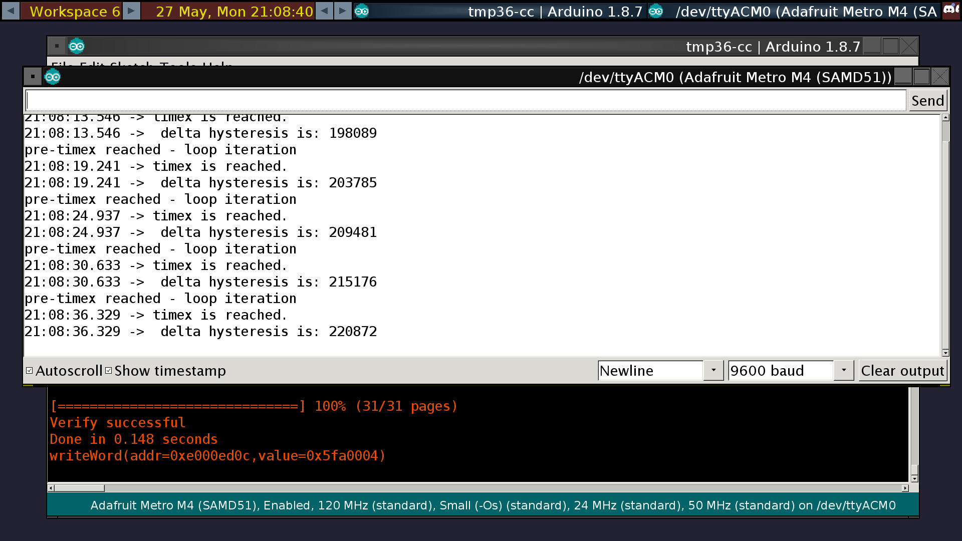
basic syntax error: timex(); rather than timex; oboy
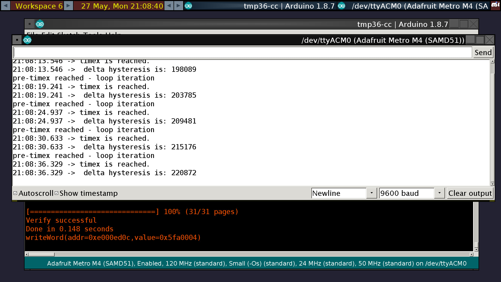
Now I just have to make it actually hysteresis. ;)
@daring marsh I got this. Thank you!
daring marsh
oki
pine bramble
Quick question, when I send something to my arduino via the monitor, I send an extra newline escape because I pressed "Enter" to send it, right?
 barren scaffold
If you type 3 characters at the serial monitor and press enter, yes, you sent 4 bytes.
pine bramble
I think gtkterm will spit out all bytes in hex for you, so that you can be sure about such things. ;)
 glass vapor
Hi! I was thinking about using an Arduino Uno for my team's cube-sat, the Centauri Delta. Does anyone think it would survive up there for 3 - 4 weeks? I am trying to find a good logic board (let's be honest 'logic board' sounds much cooler).
barren scaffold
@glass vapor seen https://en.wikipedia.org/wiki/ArduSat ? Haven't read enough to know if they did any hardening or other treatment for space environments.

ArduSat is an Arduino based Nanosatellite, based on the CubeSat standard. It contains a set of Arduino boards and sensors. The general public will be allowed to use these Arduinos and sensors for their own creative purposes while they are in space.ArduSat is created by Nanosa...
glass vapor
@barren scaffold Thanks a lot! That will help my team.... which is one other nerd and myself. Oof XD
glass vapor
Wouldn't the environment be too cold for and Arduino?
pine bramble
I was NASA certified (through a class in the Air Force) for soldering - we all were in my job. Not a big deal. Most were 'farm children' growing up and took an electronics job because they passed the test of native ability.
There's the 'industrial temperature range' to consider.
glass vapor
Interesting
pine bramble
You want good soldering up there for low weight (lead weighs a lot) and for lack of corrosion, mechanical stability.
glass vapor
Yeah, I did see a video on how to solder to NASA standards. It was pretty sound
pine bramble
You might want to look at the standards (I assume exist) for work to be done at South Pole. Many beakers (scientists) deploy experiments and probably some are hand-built.
glass vapor
Ok cool. Thanks! 😃
pine bramble
(literally cool haha)
glass vapor
Haha
pine bramble
For humans, the environment at MacMurdo Station is perhaps more harsh than at Pole, in some instances. For machinery, I think Pole wins. ;)
glass vapor
Awesome. Lots of research to do!
pine bramble
Sombody somewhere must have blabbed about how they got their student project into the space environment.
glass vapor
Probably. I also downloaded the CSLI 101 pdf for help.
pine bramble
Can you link that here? Or link to a link where it can be found?
glass vapor
I can send the .pdf
pine bramble
The clock on the Arduino may run slower in low temperatures (assuming it runs at all) so timing considerations may apply.
delay(1000) might execute in 1.093 seconds (wild guess) for example.
Let's say it's a 24 MHz clock - may slow to 23.431 MHz (just another wild guess).
glass vapor
Yeah
pine bramble
The C8051F330D chip I use has an internal 'high precision' clock (from quite a while ago when it was first designed).
Other chips relied on an external quartz crystal.
I think the first edition of the SAMD51 boards from Adafruit had no support for an external crystal, so they relied (instead) on the internal oscillator. (Not sure on that).
I think generally an external crystal is thought to be more stable but again just guessing.
glass vapor
Cool (haha_) 😉
pine bramble
I would avoid the external crystal myself, on first guess.
My boss told me to use something to adhere the crystal to the substrate (circuit board) to stabilize it mechanically.
I thought 'duco cement' when he said that. ;)
narrow thorn
@pine bramble I would think more stable from not having temp fluctuations in a stand alone oscillator vs one in a chip that could change greatly in temp
pine bramble
Dendrites when they grow (crystals) in the space environment act like shaking a can of iron filings on a circuit board would (not as many shorts, of course). /BOFH
glass vapor
Yeah. I might get a rubidium crystal oscillator that is used in an atomic clock for time keeping. It might not be practical and not in the budget. Depends on how many people contribute to the kickstarter
It's probably too large
pine bramble
devoh yeah we had actual crystal ovens on early ham radio equipment. There was a steel door (post-it note<tm> sized) on the front of the transmitter.
narrow thorn
early version of "EasyBake" ? 😃
pine bramble
There was some kind of ytrium garnet doo-dad in something I once knew about.
(spelling on ytrium unconfirmed) ;)
Yeah so the space environment changes a huge amount in sunlight vs shadow.
Very big temperature swings, probably with all the values in-between to be concerned with.
glass vapor
Yeah
pine bramble
Obviously you don't heat a large area on a space vehicle due to the energy budget.
So you could have expansion and contraction to be concerned with.
glass vapor
I can probably get some heat protection stuff from NASA. I have some friends and mentors who might be able to get me some stuff.
Probably not but worth a shot ¯_(ツ)_/¯
pine bramble
I'm guessing the space environment could also expose to a higher concentration of gamma rays (and such) that could collide with a chip and make a 0 into a 1 pretty easily. ;) (inside the chip as it operates).
So the firmware may need lots of recovery routines to guard against it.
glass vapor
Probably.
pine bramble
The space vehicle may be a high-RF (radio energy) environment from it's radio link to the ground.
So once a CubeSat deploys, it'd presumably separate by any number of feet, early in deployment.
Could cross the path of the downlink's highest energy cone. (exposed to radio waves of high strength)
Might want to count to fifteen Mississippi in the firmware, after deployment is confirmed.
🔺 🔹
Avoid design constraints that could (under any circumstance) cause high currents to flow in the port pins of the microcontroller.
So like for example if a port pin was set to PUSH-PULL vs whatever .. and it is grounded (externally, by some other circuit) that may not be so good.
As in powering a single discrete LED directly from a port pin, as you can do in casual experiments at home.
▫ ◽
afaik, if you take the usual Arduino, set a port pin to push-pull (OUTPUT mode), and operate an LED, fine .. but if you ground that same pin, could smoke that port pin (probably not visible smoke, just opens it permanently, maybe - rendering it (alone) inoperative).
I think the term 'PUSH-PULL' is depricated - I rarely hear it used anymore in this context.
I think the term 'PUSH-PULL' is deprecated - I rarely hear it used anymore in this context.
glass vapor
Ok. Thank you! Lots of tips! Hope to get Starbucks with my guy this Sunday to talk about how to NOT break our picosatellite and funding etc. We'll most likely use kickstarter
pine bramble
Don't overlook Patreon either. Takes a while to build up a following. The more you publish the better you can do by the money, I think. ;)
glass vapor
Ok cool. I will look into that as well. 😃
pine bramble
So I’m trying to do a little project. I’m a completionist when it comes to games, so why not? I’m trying to use my arduino to control my GBA so I can program the arduino as an automated shiny hunter for Pokémon ruby. Any ideas on how to do this?
I know people say automation takes away the experience but I don’t ever have the time for shiny hunting.
barren scaffold
Knowing nothing about this game, what would some theoretical automated controller need to do? Questions include: assuming an unmodified GBA, how many buttons does it need to press? How does this controller know when and which button to push?
pine bramble
The way I see it, it would need to press every button except start or select. It will walk back and forth in a loop until it encounters a Pokémon. It would use an rpg sensor to tell if the Pokémon is shiny or not. If so it will go into the inventory and use pokeballs to catch it. If I can find out how to do it, maybe even get it to battle to weaken the shiny Pokémon.
barren scaffold
To break this down further, "back and forth in a loop" means pressing what buttons in what repeating sequence? What's the RPG sensor, and how does anyone know if it's detected a shiny pokemon or a non-shiny one?
pine bramble
Whoops. RGB, not RPG
The arduino would be connected to a screen that will show the log. For walking back and forth, that means pressing the left and right buttons in that order.
barren scaffold
Connected to a screen other than the one built into the GBA (Gameboy Advance, right?)? Or is it using a camera to read something off the GBA screen?
pine bramble
Connected to a screen other than the one on the GBA. No cameras involved.
The only thing reading from the screen is an RGB sensor to detect the shiny Pokémon.
barren scaffold
So there's a LED somewhere that lights a particular color when a shiny is encountered, and either doesn't light up or lights a different color when a non-shiny is encountered.
pine bramble
Yes
barren scaffold
And this screen that shows the log is already connected to the GBA somehow? Is something reading the screen visually, or the data between the GBA and the screen, or what?
pine bramble
The screen displaying the log is connected to the arduino. The arduino is controlling the GBA. The RGB sensor is also connected to the arduino. When the RGB sensor picks up the color pallet of a shiny, it tells the arduino to go into a different state where it will try and capture the Pokémon.
So the external screen is merely a way for me to see if the detected Pokémon is shiny or not.
barren scaffold
So the Arduino RGB sensor is pointed at part of the GBA screen, and there's no single LED lighting up a particular color.
pine bramble
Exactly.
barren scaffold
Do you already have any or all of the hardware required aside from the GBA?
pine bramble
I have the link cable for multiplayer. I’m not sure what parts I need in order for the arduino to connect. I think it’s possible to connect the link cable via serial ports.
barren scaffold
Where's the link cable come into this? Does that let you take action without physically pushing buttons?
pine bramble
I’m hoping so
barren scaffold
That would be a good thing to find out beforehand. Protocol, expected voltage, does it actually let you take action, etc.?
pine bramble
I’m doing research on it now. Hopefully it will work.
iron shell
I'm trying to use the ScanNetworks example in the WIFININA Library but I keep getting this error that the SPIWIFI_SS pin is not declared in the scope. I'm using the exact code from examples and nothing is changed.
https://pastebin.com/n5VX7dza

(Using Adafruit AirLift)
barren scaffold
Is an AirLift the same thing as a Teensyduino or any of the other boards listed in the #if defined lines above? If it's a different board entirely, then you could make your own #define lines for mapping pins to particular names.
 safe shell
@iron shell What's your main processor board... is it one of the boards in the conditional pin definitions?
iron shell
Do you mean like my microcontroller? If so, Arduino mega
safe shell
@iron shell Yes, that's what I meant. So it's falling through the #if defined conditional and no pins are getting defined.
I haven't done anything on a mega so I don't know what the board's constant is, but you'll need to add a block of #defines for the pins you're using to connect to the Airlift. (I'm assuming you've downloaded and installed the WiFiNINA library rather than using the standard WiFi ...suspect there'd be a different error if not)
pine bramble
Can you accidently electrocute yourself with an arduino? Like if you brush a resistor by accident while the thing is powered?
barren scaffold
Let’s say exceedingly unlikely. 48VDC for power over Ethernet is basically safe, and Arduino shouldn’t have anything over 5V. https://electronics.stackexchange.com/questions/267789/how-safe-is-48v-dc

Electrical Engineering Stack Exchange
In many Power over Ethernet (POE) setups the transmission voltage is 48V or slightly more. While higher voltage has obvious efficiency advantages, how safe it is? Is there any risk of electrocution...
 north kelp
It's much more likely that someone will electrocute the Arduino with static electricity. But this is not common, either. Still, I take care to discharge static by touching grounded metal before handling sensitive boards.
 crystal mesa
@glass vapor There are at least two good series of books that talk about the challenges of designing electronics for space and how to test for them. Sandy Antune is the author for at least a few volumes in the Make: series, and Patrick Stakem is the author for at least a few in the other.
You should be able to put "cubesat" into Amazon and get to them fairly easily.
@pine bramble As I was taught, the number one rule of electronics safety is to always make sure that if you accidentally touch a circuit, the path to ground does not cross your chest. It's really unlikely to get hurt by normal Arduino voltages, but it doesn't take much current to mess with your heart. And you won't always be working with just Arduino components, and they won't always be safe (failures make the weirdest stuff happen), so getting the good habits built now will keep you safe later when you accidentally short something that shouldn't be shorted.
glass vapor
Awesome! Thank you!
pine bramble
Somewhere between 28 VDC and 50 VDC you may need precautions. Under 28 VDC, not so much.
Biggest safety issue with a car battery isn't the massive energy (in Joules) it can deliver per second -- it's the buildup of .. Hydrogen, I believe .. can explode.
(You can also accidentally start a fire with that much juice on tap - use fuses.)
 vital tartan
Hi
pine bramble
greetings from the Planet Earth. I am their leader!
 runic brook
@daring marsh you recently demoed USB mass storage on an Arduino program. What would you say is the possibility of binary files being dropped onto Arduino to be executed or used?
inland crag
you can already export an arduino sketch as a bin and then convert that bin to uf2 for an executable. not sure if that's what you want to do
 modern seal
Does any sort of service exist where you can batch order atmegas with preburned sketches?
I've tried using a nano as an ISP to atmega chips and I am not having any luck after days of trying.
 north stream
DigiKey and many board houses will preprogram things for you, but it should be possible to do so with a Nano if you supply the right signals. Note that if the atmega is in an odd clock mode or has protection fuses set, you'll need to use "high voltage" or "rescue" programming.
Which mega do you have? What was programmed into it previously?
modern seal
I have 10 Atmega328p's.
Trying to even program just one, device signature coming back as all 0's.
As of right now, they don't have anything on them, not even a bootloader. So I can't even burning bootloader right now.
And I'm not quite sure how to use high-voltage, or rescue, programming, that you speak of.
north stream
Hmm, no signature at all. Sounds like a reset, ISP, or clock problem.
modern seal
Tried several different things. Including hitting the reset switch on the programmer anywhere from one to five seconds before I try uploading the bootloader, I tried two different Nanos as the programmers, tried using a capacitor between the reset pin and ground on the programmer. You name it.
With my luck, it's probably something right under my nose that I haven't tried yet. Lol
People on the tutorials make it look so easy to do.
modern seal
Have everything on a small breadboard.
north stream
What are you using as a clock source?
modern seal
Clock source?
( by the way, these two pictures are slightly outdated, I have the crystal connected to ground with two 20 picofarad capacitors, didn't have 22.)
north stream
20pf is close enough (there's a lot more than 2pf of stray capacitance in a breadboard anyway).
modern seal
Yeah, that's what my electronic buddy was saying. He said a difference of two really isn't going to matter at all.
Like 99% of the error messages that I get when trying to burn the bootloader, are related to not being in sync.
north stream
Yeah, it's not getting back the data it's expecting. I'm guessing it's a wiring error, but I can't tell from those pictures.
Which sketch are you using? ArduinoISP? OptiLoader? Something else?
modern seal
ArduinoISP
I could paste the link here to the exact tutorial that I'm following, if you would like.
On top of that, when I get home, I can shoot a short video showing my wiring and setup.
north stream
Just a clear, well lit picture from straight above is probably sufficient. If you can't get ArduinoISP working, we can try OptiLoader (which is really smart but does some creative things with power).
Where are you based? I'm on the east coast of the US.
modern seal
Alrighty, I will post a good overhead picture when I get home. And I'm in Missouri.
north stream
Ah, not particularly local. If all else fails, I have a genuine Atmel STK-500 that will program anything.
modern seal
Well that is neat. Genuine stuff is never a let down. Lol
north stream
I got into AVR programming before Arduino became popular, so I still have some of the basic low-level hardware, which comes in handy from time to time.
I had started microcontrollers with the PIC line, but Microchip kept changing their protocols and not sharing information about them, and their software only worked with DOS. I eventually lost patience with that, so went to AVR, which was very well documented.
modern seal
My goal is to eventually use something like AVR, Arduino makes things SO easy, but simple functions like digitalWrite() and digitalRead(), and delay() use more code and processing time.
north stream
Happily, it's an easy transition to make. You can access the hardware directly even in the Arduino environment with code like ```c
PORTB = 0x80;
It's not hard to get the Arduino tools to give you the assembler version of the code you wrote so you can get a clear idea of what's happening under the hood.
modern seal
Well that's good. I'm sure one could write their own Library with bare minimum code, to replace read and write Arduino functions.
north stream
Yup. The beauty of open source is you can dive in, see how the existing code works, and replace any of it you like.
modern seal
That's very much true. Definitely save a lot of room on the chip for more code.
north stream
I've come up with custom board definitions, memory maps, modified libraries, you name it. It's fun.
modern seal
Sounds like it, I gotta do that too. My programs are lengthy and i need more than 32,768kb.
Back relating to the topic with my programming issue, the Nanos that I am using are Chinese clones, which for all I know, could be the root of my problem. However, in a tutorial that I am following, this person is using a clone as well.
 sturdy bobcat
Well, it's not like there's one single Chinese clone company. It's a giant distributed enterprise.
I'm rebuilding a bunch of my light painting hardware and I have two boards from 2006 that I never got much use out of. One of them had firmware in AVR assembly and the other was using AVR C and the current set that I'm working on is Arduino-compliant because I decided it wasn't helping anyone for me to spend so much time horking with the environment and low-level stuff.
Lesee... when I was failing to do exactly that with my STK-500 as programmer, I ended up ripping out the ISP wires and putting them back and it suddenly worked. I definitely had the MOSI and MISO lines messed up and that caused a problem.
north stream
Looks like you don't have reset (pin 1) hooked up: it should go to D10.
I don't know why you have pin 21 hooked to +5V (purple wire).
I'm not sure why the LED is there.
You have a long path to ground for the crystal capacitors, maybe hook them to the pin 8 ground instead of the ground rail.
Looks like you have the reset capacitor connected to the Nano's reset instead of the target CPU's reset.
modern seal
-Fixed
-The tutorial I followed showed pin 7, 20 and 21 on the atmega hooked to 5v.
-I am trying to upload blink just to test the standalone atmega, so the led is hooked to D13 of the atmega
-Fixed
- so use the reset capacitor on pin 1 of the atmega to ground?
Got it! Bootloader burned!
All that stuff that you just mentioned helped.
Going to see if burning blink works.
Getting time outs here.. hmmm.
north stream
Now that the bootloader is burned, you can talk to the chip via serial.
modern seal
By serial l, do you mean via TX and RX pins?
Never mind on all that stuff. The reason it was timing out, was because I was trying to upload normally. I didn't select the upload using programmer option. LOL
modern seal
The first Nano that I used, seems to have bricked. Because after uploading the Arduino ISP sketch to it, I can't upload anything else over that, I always get not in sync errors.
north stream
Once the bootloader is installed, just use it to install code with the serial interface.
modern seal
I'll definitely give that a shot. Thank you so much for your help.
 long sphinx
Has anyone used GxEPD2_BW and been able to pass a reference to a method in a different class?
 fierce ridge
Anyone here know of a way to calibrate/reset a BNO055 IMU ?
I want to reset it and make calculations on gyro/accel data after the sensor is at a "starting" location.
pine bramble
guys i am baffeled.
last 3 MC's i bought dont work.
now i bought a sparkfun SAMD 21 mini breakout
but just like all the others it wont complete flashing.
it just gets stuck
i tried updating i tried downgrading,
i tried fresh drivers..
north stream
How are you flashing them? USB bootloader? JTAG? Something else?
pine bramble
usb bootloader
north stream
Where does it get stuck? What happens?
pine bramble
Fresh install
Arduino: 1.8.9 (Windows 10), Board: "SparkFun SAMD21 Mini Breakout"
Sketch uses 10104 bytes (3%) of program storage space. Maximum is 262144 bytes.
java.io.IOException: Cannot run program "{runtime.tools.bossac-1.7.0.path}/bossac.exe": CreateProcess error=2, The system cannot find the file specified
at java.lang.ProcessBuilder.start(ProcessBuilder.java:1048)
at processing.app.helpers.ProcessUtils.exec(ProcessUtils.java:26)
at cc.arduino.packages.Uploader.executeUploadCommand(Uploader.java:129)
at cc.arduino.packages.uploaders.SerialUploader.runCommand(SerialUploader.java:383)
at cc.arduino.packages.uploaders.SerialUploader.uploadUsingPreferences(SerialUploader.java:197)
at cc.arduino.UploaderUtils.upload(UploaderUtils.java:77)
at processing.app.SketchController.upload(SketchController.java:732)
at processing.app.SketchController.exportApplet(SketchController.java:703)
at processing.app.Editor$UploadHandler.run(Editor.java:2070)
at java.lang.Thread.run(Thread.java:748)
Caused by: java.io.IOException: CreateProcess error=2, The system cannot find the file specified
at java.lang.ProcessImpl.create(Native Method)
at java.lang.ProcessImpl.<init>(ProcessImpl.java:386)
at java.lang.ProcessImpl.start(ProcessImpl.java:137)
at java.lang.ProcessBuilder.start(ProcessBuilder.java:1029)
... 9 more
An error occurred while uploading the sketch
This report would have more information with
"Show verbose output during compilation"
option enabled in File -> Preferences.
north stream
Ah, that's not getting stuck, it isn't even getting started. Looks like the loader tool (bossac) is not installed.
You'll need to install both the Arduino SAMD board packages as well as the vendor board packages.
pine bramble
i saw there was a new update for the sam libs
fixed.
😐
@north stream i'm testing the usb drive fuctionality
👌
pine bramble

GitHub
Arduino IDE support for TinyUSB stack. Contribute to adafruit/Adafruit_TinyUSB_Arduino development by creating an account on GitHub.
pretty cool
So i saw you can config them to act as usb storage.
Yet another interesting way to add things like settings or configs
 stark bridge
Yes, it's also nice to see that they appear to be using native code for the underlying interface. For a while some of the Arduino stuff was build using ASF. So you ended up with layers on top of layers and a simple program could bloat to enormous size when compiled.
pine bramble
what i always found was when i used the pic16X8X chips is that you sadly had to use ASM
but your code was, cleaner, faster and way less limited
But your code took ages to write
stark bridge
All but the oldest PICs support C. In fact I think they all do support C, just some of them lacked certain instructions that made it easier for the C compiler to generate code.
PIC ASM is painful to write though. AVR ASM is so much nicer in comparison.
But up above I was referring to ASF (Atmel Software Framework), not ASM (assembly language).
pine bramble
i havent tried avr asm
 mild elk
Is it possible to control an RGB led with PWM while having the CPU doing something else?
stark bridge
Yes. That's the purpose of the PWM peripheral. It generates the waveform without the CPU having to do anything.
mild elk
Ok, but if I wanted it to cycle through all colours automaticly?
stark bridge
You'd have to change the duty cycle each time you want to change the color. It will be a lot more work for the CPU but still far less than bit-banging the PWM on a GPIO.
mild elk
I have a program running on my arduino, and i'd like it to control that LED to cycle through all colours, but the CPU is busy most of the time
Its a clock with DS3231 and character LCD
stark bridge
And that is enough to keep the CPU busy all the time?
mild elk
I mean, I can't think of a way to measure how much could I still squeeze from it
Maybe I could make it blink an LED every time it completes the main loop?
stark bridge
What makes you think the CPU is too busy to handle cycling an RGB LED? If all you're doing is reading the time from the RTC and then displaying the time on the LCD that should use almost no CPU power at all.
mild elk
🤔 I can post my code so You judge how much CPU power it takes
stark bridge
OK, if it's not too long I can look at it. Post it and let's see.
stark bridge
These variable names are extremely hard to interpret. It's better to use longer variable names. What is "t" in the switch statement used for?
mild elk
t is mode
stark bridge
Using shorter variable names doesn't save any memory in the actual code.
mild elk
It's used to switch between normal running mode and setting mode
stark bridge
Also you don't want to use interrupts to detect button presses directly. But that's another issue for another time. The mere fact that you have all those delay statements in there (i.e., delay(200);) means you have tons of CPU time to spare. The CPU can execute 3.2 million instructions during a 200 ms delay. Calculating and changing a PWM duty cycle will probably take less than 30 instructions (unless you use division in which case it will be more like 300, but still...300 out of 3.2 million).
Basically, the CPU is probably being used at less than 1% capacity in that program.
mild elk
Ok, so I should be able to add PWM instructions on the end and it should work?
stark bridge
Well, the code will need to be added at the right place. And it's a bit hard for me to follow due to variable naming and use of magic numbers. (for example, what does it mean when t is 6, or 51, or 53? those should be constants or #defines, not just bare numbers)
But you have plenty of CPU resources to spare. Cycling through values in the PWM registers is not going to overload it by any means.
I also recommend changing the variable names to be more descriptive. If "t" is the mode variable, call it "mode". If h10 is the 10s digit of the hour, call it "hour_tens_digit".
mild elk
Ok, thanks for help! 😀
stark bridge
You're welcome.
 tough tiger
Does anyone know when Adafruit-GFX-Library 1.5.4 and Adafruit_Arcada 1.4.0 (or 1.3.1) will be made available with the new framebuffer features?
bool Adafruit_Arcada::blitFrameBuffer(uint16_t x, uint16_t y, bool blocking, bool bigEndian)
That is to say, the possibility of combining the use of blocking and bigEndian flags 😃
Super excited to have these two new features in Adafruit-GFX-Library:
void Adafruit_GFX::drawRGBBitmap(int16_t x, int16_t y, const uint16_t bitmap[], int16_t w, int16_t h)
void Adafruit_GFX::drawRGBBitmap(int16_t x, int16_t y, const uint16_t bitmap[], const uint8_t mask[], int16_t w, int16_t h)
I'm using a Arduino Mega with the Adafruit Airlift. I am using the WiFiWebClient example that comes with the WiFiNINA library.
I keep getting this error: https://williamd.co/u/sxoa.png and cannot fix it. SSID and Password are both correct and have rewired to make sure I am doing everything right. Wired as shown in this tutorial however on a mega: https://learn.adafruit.com/adafruit-airlift-breakout/arduino.
Help is greatly appreciated! 😄

 left parcel
The JSONdemo works fine for me on a Mega+Airlift. Check wiring and soldering.
long sphinx
is there such a thing as a global function? That I can call inside a class method
 vague kettle
heya! prolly a silly question, but i figured i'd ask to see if im reinventing the wheel
im making a space station tracker. a raspberry pi grabs some data from the internet, and does the hard math. im going to send 2 lines of text, then 2 int's from the raspi to an arduino over serial, arduino drives the motors and 2x16 char lcd
im thinking ill have the pi spit out 1 'batch' of data, that is what to put on the LCD, and where to move the motors. then the arduino will respond that its ready for more data. repeat forever
am i right to do it manually like this? have it send 1 line of char[]. then the next line of char[], then the 2 ints, then the arduino moves the motors and responds OK
im i making this too hard for myself? am i barking up the wrong tree?
 spice nacelle
smokkin - that process is fine.
You might also be interested in the Firmata protocol:
https://github.com/firmata/protocol
vague kettle
ooo that does look promising. but i think ill keep it in my back pocket for now, as long as the way im thinking is reasonable
spice nacelle
Yeah - should be fine.
spice nacelle
You could experiment - and then see which one you prefer....
vague kettle
im still in the exp phase anyway, so i just might plug it in and play with it
structure+motors are done, eventually ill buy a nice mounting plate, but for now its done and works. i can control the motors from the arduino. i have the lcd working on the arduino via software serial
i have the orbital tracking code working on the pi, and last weekend i got curl working on the pi, so it grabs the data from the internet itself. next step is just to send that data from pi to arduino
spice nacelle
Nice
vague kettle
later on ill get a GPS chip, for now i just have my location hard coded. also need a compass, for now ill just point it north by hand before powerup
then a nicer display
thank you for your help 😃
 bleak glacier
@mild elk These guides might help to figure out what you want to do. If you can visualize doing things in stop-motion step by step, you can program your arduino the same way. Good luck. https://learn.adafruit.com/multi-tasking-the-arduino-part-1/overview https://learn.adafruit.com/multi-tasking-the-arduino-part-2/overview https://learn.adafruit.com/multi-tasking-the-arduino-part-3/overview

Make your Arduino walk and chew gum at the same time.

Excuse me while I interrupt myself...

Unleashing the power of the NeoPixel!
 wet crystal
Do I need a logic level shiftr to run ws2812 with esp chip?
inland crag
technically: yes
practically: no
 charred salmon
This will likely end up one of two ways. Either someone will tell me this is a horrifying idea, or someone will point me at an existing library that does what I'm trying to do.
So right now I've got a 128x64 monochrome oled screen driven by the Adafruit_1306 and Adafruit_GFX libraries. All well and good, but what I want is to have a drawing area that is larger than the screen, and to be able to just grab a screensized chunk of that, copy it to the real 1306 buffer, and display that. There's just a bit of a problem though.
I figured the dirty way of doing this was to create a second fake screen of the desired size. Too bad the 1306 library fails to work properly if I pass "invalid" screen sizes. If I pass it normal ones, my test works, so I know my idea works. I thought I'd try creating a graphics object by calling the constructor for the GFX library, but then I have no buffer.
The weird thing is that I can't even figure out why the 1306 library fails as the only thing it seems to not do is send a few commands to the screen, which is fine because said screen doesn't actually exist.
north stream
Should be doable if your CPU has sufficient RAM for both buffers. However, you'll probably have to modify the source code of the library to allow this, at which point, you may want to just create a RAM framebuffer instance and a way to blit a window into that onto the actual display.
charred salmon
Yeah, I've got a Trinket M0 right now, which boasts 32kB RAM, and since it's monochrome I need only 1kB per full screen, so even a 3x3 screen buffer should "only" take a third of my RAM. If I can, I'd like to avoid creating a whole other display instance just for simplicity since
  canvas.begin(SSD1306_SWITCHCAPVCC, 0x3C);
  display.begin(SSD1306_SWITCHCAPVCC, 0x3C);```
looks silly, and really is just awkward.How to create just a graphics object, and attach it to a buffer, I don't know though. I'm not at all skilled in low level things, so without an explicit constructor, I really don't know.
If there's a library to just create and work with a framebuffer, that'd be fantastic.
 tight badge
Hello. I've been trying to get a code to work with my circuit playground express, Bluefruit Flora, and a neopixels strip. I would like to put neons on my motorcycle and change the color with my phone. I've tried some different sketch's but none seem to work with the pixel strip and the BLE together. It is an RGBW strip with about 15 pixels. Has anyone here done this type of project on Arduino with a CPX?
charred salmon
First thing I would try, if you haven't already, make sure you can at least drive the NeoPixels without the bluetooth.
north stream
I think the GFX library sort-of does the frame buffer/canvas stuff you want, but I think you'd have to do some low-level hacking to get it to work on its own.
tight badge
I'm really novice to Arduino. I've done plenty with makecode. I see how to install libraries and define objects. I just can't seem to mix the parts of each sketch I need in without issues.
 fallen linden
Good morning. I've done a bit of work using the Adafruit_8x8Matrix Class/Library. Is there a related Class/Lib that supports combining multiple 8x8 matrices and treating them like one larger matrix? I think I've seen such a thing for the neopixel matrices.
long sphinx
Anyone in here having to support different epaper screen sizes and using GxEPD2 as their display driver?
north stream
The LED backpack library supports 8x16 matrices, which is a start.
charred salmon
Ok, digging deep into the GFX library, there appear to be functions for generating arbitrary canvases.
All experimental.
Well, worth a shot.
Ahh, darn. It lacks certain critical features. Like grabbing the state of a pixel. Hm. More work needed.
tight badge
I'll try the GFX library and see how I do. Thank you!
charred salmon
Oh this is for something very different. Though, it might work?
fallen linden
@north stream Thanks. I'm looking to string together as many as 8 8x8s side-by-side to make a scrolling message display. I'm working on creating a Class of my own that will do this, but suddenly thought to ask if anyone else has done it yet.
north stream
I think that's how @arctic dove made the programmable sash that is effectively an 8x160 pixel display.
Documentation here https://www.timbermonson.com/microcontrollers
 sharp pebble
I'm worried I might have killed my Hallowing.
I tried to upload to it when suddenly I got a windows error that the USB didn't have enough power. I had stupidly connected it to a keyboard that has a USB hub in it, without thinking about the power.
Ever since I can't upload to it at all, I just get an error about missing files.
Is there a way I can fix it?
fallen linden
@north stream I remember him talking about that here. @arctic dove Did you share any of the code you used to drive the multiple matrices?
north stream
USB should reset if you unplug it, wait a bit (in case the polyfuse has heated), and re-plug it.
 short tangle
Hi, Im beginning in electronics and I have a doubt about a 3.7V 95mAh lipo ... My multimeter shows 2.57 V, is it acceptable to charge it ? I wouldd say yes as long I'm using a protected lipo charger board ? Thx for yr help
north stream
Yes, should be fine to charge.
pine bramble
I'm a bit confused about high/low on a gpio and analog write and why digital is an improvement if it can only have two values. Does analog write means it can output less than 5v on a gpio or is it simulating that? And what does 5V means vs 5V logic
pine bramble
To make it more simple, my understanding is that using analogwrite(125) simulate a lower voltage than analogwrite(255). Does this also means that I can use a resistance that is 50% lower as the voltage is 50% lower?
Or will the LED blow because it's just simulated voltage?
 boreal vessel
You can use a smaller resistor
The voltage drop across the led will be the same, but since the supply voltage (from analogWrite) is smaller, you need to use a smaller resistor
pine bramble
will a multimeter give a lower voltage? I don't understand how it is a simulated voltage as arduino seems to says
boreal vessel
There's no simulation, the voltage being written is very real
pine bramble
Logically it should save power too if mA stays the same, right? So I I only have 1 led I should supply it the bare minimum operating voltage it need for it's drop. right?
ie: I should use analogwrite(127) and uses a 80ohm or more resistance so the battery last 2x longer powering the led
Or it won't matters because the rest of the arduino uses batteries when idle no matter the load connected to it?
crystal mesa
@pine bramble are you familiar with the concept of duty cycle?
 turbid iris
Anyone know if there is a USB video gadget code Arduino libraray avalible? Before I go and write one. I'm looking to make a deivce act as a usb camera with a video stream comming out. No idea if it'll be usful, just something I want to do. 😃
bleak glacier
@turbid iris Not sure what you had in mind but in general, arduino boards usually don't have the processing power to do video. You might want to look into raspberry pi to handle images, sound, and video. Good luck.
pine bramble
Arduino can read 54 gpio with 8 bits each 925 times per second (wild approximation). We are far from the bandwiidth needed for even a 24 bits animated 128*128 animated gif at 60fps
Now if you want to follow a mmmonochrome bright line with a low res camera with 8 bits colors that might be more doable with arduino
 steel aurora
So i tried to update my Hyperion ESp8266, running Adalight (with too low Baudrate, thats why i need to reflash it). But i just get this error... I installed various versions of FastLED, Esp8266 Board Library etc. Someone know whats wrong? Just followed this guide (https://hyperion-project.org/threads/diy-amblight-project-guide-hyperion-ws2801-ws2812b-apa102.8/)
turbid iris
I don't want to read a camera, I want the device to behave as if it was a camera presenting a video stream to the USB. Looking at USBAPI and USB Video Class 1.5 documentation. As to why, why not. I have had an attiny85 doing VGA. 😃
Using an Arduino Zero as this has a SAMD21 on it with native USB.
narrow thorn
Just a heads up for fans of FastLED. PR #803 was merged into the master branch. M4 support is working again. Tested on my ItsyBitsy M4. I take no credit for the change.. just the person that made the fix disappeared and the code was good so I made a pull request for it.
sturdy bobcat
Yay! I loves FastLED.
narrow thorn
He has not pushed a new library version yet.. but it should be showing up in 3.2.7 (or whatever he uses as a successor to 3.2.6) when it comes out.. or just grab the library yourself and use it.
steel aurora
 olive carbon
@upbeat basalt did you ever look at ArduinoAVR code, and see if i can make a feather into AVR programmer? i think it ends up bit bang it out?
north stream
Might need level shifters if it's a 5V Arduino
 upbeat basalt
@olive carbon, I just compiled the ArduinoISP.ino sketch for CircuitPlayground Express (M0) and it goes through compilation.
I'm using my CPX for somthing else right now. Doesn't have another M0/M4 board so I can't test but that seems pretty much positive
olive carbon
i have CPX also
using CPX to light 3d Printer, spinning a white led around it gives different angles so i can see what is being printed very well
upbeat basalt
It's just that I don't have a feather. But as far as you can chose the right target board in Arduino IDE, you should be good
olive carbon
kk ill just be sure to check logic of target chip im trying to AVR program as @north stream suggested
 sacred apex
Hi, am using the LIS3DH board with Adafruit library and just wondering if anyone has had any luck with the orientation functionality? It's in the datasheet but I can't seem to get it working. Have been tweaking the Adafruit library for the attempt. There's a getOrientation function listed in the header file, but no functions in the .cpp. Whenever I read the INT1_SRC register, it's always empty.
bleak glacier
@sacred apex Maybe the guide will help. I remember seeing something else with an orientation app or procedure used. Good luck. https://learn.adafruit.com/adafruit-lis3dh-triple-axis-accelerometer-breakout/overview

Triple Axis, Tap & Double Tap, & 3 ADCs!
sacred apex
@bleak glacier Thanks. I read through the guide and it mentions the orientation functionality but doesn't have any details. I've looked through the datasheet and it's definitely there. In the Adafruit arduino library header file, there's a public function listed getOrientation, but there isn't a corresponding function in the .cpp. I've been trying to write my own using the Adafruit library as a foundation but I'm not having any luck. I was sort of wondering if the reason it's in the header file and not the source is that whoever wrote the library couldn't get it to work? Whenever I read the INT1_SRC register I only seem to get 0. Thanks
bleak glacier
@sacred apex Sorry, I haven't use the LIS3DH. You might want to go to the help forum on the Adafruit site and post your question there. There should be a category that is for sensors or the like.
sacred apex
@bleak glacier ok no worries, thanks
 eager jewel
Hi @sacred apex, if you could file an issue under https://github.com/adafruit/Adafruit_LIS3DH for the missing function (and possibly submit a PR), that would be appreciated. Thanks.
GitHub
Arduino Library for Adafruit LIS3DH breakout board - adafruit/Adafruit_LIS3DH
long sphinx
Has anyone made a product with an arduino, lipo battery and solid it online to people (in the united states)? If so what all did you have to go through for compliance, certification, etc.. Or do you just sell on Tindie or some other platform?
short tangle
@north stream Thanks about de lipo 3.7v tension advice ;D
 patent marsh
Has anyone made hardware PWM work on a samd51? I’m trying via Atmel Studio but not having any luck.
Unless my atmel start configuration is just hopelessly wrong, their hardware abstracted PWM library doesn’t seem to work with the samD/E5X series yet.
On the scope I can see and set a period but the duty cycle setting has no effect
There’s like a 3ns blip at the transition from one period to the next
But otherwise it always 100% duty cycle
north stream
I suppose you could try bypassing the library and writing the registers directly
 random oyster
if you post the code I could take a look through
north stream
Or reading the registers to see what the library actually did
random oyster
if you want to go through the pain of setting up MPLAB Harmony 3, you can generate code with that framework too and compare 😄
patent marsh
I don’t have the code with me at the moment but I can post something on Monday. I do have MPLAB X installed because I needed to previously work on a PIC device.
I was hopeful I wouldn’t need to write to the registers manually because at that point I don’t think there is a whole lot of value to using atmel start except to make sure you don’t wire up something wrong/double assign a sercom port.
Also digging through and parsing a 1k+ page manual for the one bit of information you need is never fun
Control + F actually will return too much information to be very helpful
And all of it is on a low abstraction level which makes it easy to screw up
 stable forge
@patent marsh In CircuitPython we write to registers instead of using the ASF4 drivers. If you want to see our code: https://github.com/adafruit/circuitpython/blob/master/ports/atmel-samd/common-hal/pulseio/PWMOut.c
patent marsh
Thanks, that’s helpful. Looks like it’s going to be the painful route of writing my own function but having the gist available will significantly decrease the amount of time this takes. I have a Metro M4 on the way to test out the existing circuit python implementation but the end application must unfortunately be in C.
stable forge
did you try the arduino PWM?
patent marsh
Board is custom so I’d need to do a fair bit of setup to even use the arduino ide and arduino core.
Arduino PWM just does delay calls underneath though I thought.
Which means the actual duty cycle will vary some on interrupts
stable forge
from our samd51 arduino core
it uses the TC's or TCC's
like CPy
@patent marsh it does not use delays; it uses the timers to run the PWM autonomously
patent marsh
The implementation appears to be okay. I’ll test it out next week on a Metro and if it works okay there I’ll either need to figure out how to get my board to support circuit python or I’ll need to make a similar implementation using that one as guide.
pine bramble
ok i'm feeling confident suddenly the Arduino i thought i brutally killed in a rouge pi experiment decided "yes i will assimilate this bootloader"
north stream
Yay! One thing I like about the old-style Arduinos was that it was easy to replace the chip.
Oddly I don't think I ever needed to, even though I made lots of mistakes that could have damaged something
safe shell
Arduino analogWrite seems to be PWM. Is there a way in Arduino to take advantage of true DAC analog pins with a continuous analog voltage?
 burnt island
I'm pretty sure it does use DACs when they're available
pine bramble
Been digging around for a Atmel ICE programmer in South Africa that not laughably over priced
isn't there a diy substitute?
i'm hoping to use this samd09
patent marsh
You can maybe use openOCD and a pi but good luck with figuring out the right sequence of commands to send
I’m not aware of a DIY direct replacement for atmel-ice
pine bramble
yeah a ICE programmer compatible with sam chips is US$250 here
and i honestly would prefer a atmel approved product
pine bramble
Has anyone played around with these mass storage boot loaders?

GitHub
SAM Boot Assistant Reloaded - Combo USB CDC+MSD Bootloader for Atmel/Microchip SAMD21 microcontroller - watterott/SAM-BAR
 sour tide
@pine bramble our uf2 bootloader is like that (and the repo links to it)
pine bramble
ahh i see
 granite orchid
I’m trying to get input from 4 different piezosensors and determine which area is being hit
If I implement a filtering system (find highest input, etc etc) to determine the output (Keyboard.write(“d”) for example), would it affect the overall latency
Or is it negligible
Would most of the delay come from the code itself or the board?
bleak glacier
@granite orchid With arduino, the sensing should be pretty fast, it can be simple as an on/off switch or also gathering how hard a hit, I guess it depends on what the code is doing in the meantime like running a light animation or calculations that you would have to structure your code carefully. Look for projects that are drum machines, dance pad controllers, MIDI controllers, keyboard emulators to see the issues you have to consider when making a system as responsive as you want it to be. Good luck.
This 3 parter helps with understanding the capability of arduino when it runs https://learn.adafruit.com/multi-tasking-the-arduino-part-1/overview
Make your Arduino walk and chew gum at the same time.
Excuse me while I interrupt myself...
Unleashing the power of the NeoPixel!
granite orchid
@bleak glacier thank you! I’m currently trying to make a tatacon for taiko no tatsujin. There shouldn’t be much background processes (if hit>thresold then keyboard.erite), but I’ve been thinking of issues like running all 4 (or more) sensors simultaneously. I’ll take a look, thank you!
I was looking into running 4 threads simultaneously on pro micro but couldn’t find much info
north stream
I'd probably use interrupts to make sure to catch events, but the interrupt routines would simply store a value, then the next pass of loop() could look at the latest values, do a little processing, and decide whether a given beat should register. I wouldn't attempt to multi-thread such a small CPU, just make an efficient single thread, and possibly use interrupts to make sure nothing was missed.
 pulsar charm
has anyone tried unit testing on Arduino, like AUnit?
I'm not a native c++ programmer and the documentation for this language is a hard read
mild elk
I made a digital clock with 16x2 character LCD, DS3231 and standalone 328p, but if I leave it running it often freezes and even pressing reset button does not fix it. Only when I unplug it and plug it in agin it will work properly. Until it freezes agin of course. Any ideas why this might happen and how to fix it?
north stream
I'm guessing it's either running out of memory, or has a wild pointer that's corrupting something. You can use some of the memory debugging utilities to check for a memory leak. The wild pointers are trickier, usually I end up using checkpoint printouts, and adjusting them until I narrow down where it was when it stopped working, then working backward from there to try to figure out why. An in-circuit debugger is invaluable, if you have one. The other workaround is to set up a watchdog timer that self-reboots if it goes off into the weeds.
Note: do a clean compile of everything, and examine every single compiler warning: they're often useful clues.
mild elk
I'm working with arduino IDE, and it never gave any warnings
I'm probably going to look through that code and see if I can improve it
But I don't think i can do much since I've done it once already
I can post my current code if You want so maybe You find something
bleak glacier
@mild elk What kind of display are you using, is it an I2C backpack alphanumeric? Maybe there is some incompatibility with the libraries of that and the clock module.
bleak glacier
Only thing I can suggest is run the clock module without the display, just watch the output on serial monitor to try to rule out the display added on. I've found the libraries for those character displays work for general purpose but may not be 100% compatible for the hardware you have on hand.
mild elk
I was thinking it may be a problem with crystal stopping oscillating because the CPU literally stops working and when I reset it it only clears the display
Or maybe my power supply is crap
I'm gonna run it with different power supply and see if the problem persists
But running it with serial monitor is also a good idea
I'll just have to connect rtc to my arduino because the standalone one has no serial built into software/hardware
north stream
Oh, I missed the detail that reset doesn't fix it: that is unusual.
mild elk
Yeah, isn't it?
 merry sierra
Hello, im using ESP8266 with DHT22 module on board which could be powered with voltage from 3.3V up to 12V - got regulator on it...
I'm getting funny thing over here ... when im powering it from Arduino with 5V it works perfectly
but when i try to power it with 2x or 4x AA battery all i get its very very wrong numbers like:
Temperature: -3277.3 adn Humidity: -1.9
I have tested it with multimeter, the board gets 3.3V (as it should - normal) when powered with battery and all batteries are brand new ...
so I dont get what could be wrong at all ...
I have tested on arduino 5V for 48H+ getting every 1 min readout without a problem
anyone got idea what is going on here ?
this is the type of the module:
north stream
Are you connecting the negative rail of your board, your batteries, and your Arduino all together?
merry sierra
naah
The arduino which i had mentioned was acting only as PSU
nothing elsee
now with battery would it be standalone
north stream
How do you read the temperature?
 magic field
 north stream
What I'm asking is how you get the readings from the DHT22 if it's not connected to the Arduino.
merry sierra
with ESP8266 which is connected on this board with yellow pins (check image)
this is connected on those yellow pins <-- the ESP8266
north stream
It ought to work with 4xAA (if they aren't worn out). I would not expect it to work with 2xAA.
merry sierra
some people use 2xAA too i saw it on web and it works... anyway.. i said before they are brand new and yes it doesnt work even with 4x AA
So with 4x AA i got 6,5V ...
granite orchid
Would AC on analog input ruin the pin? I’m only interested in the top half of the AC
I’m using pro micro if that helps
Do I need to make a half bridge rectifier if, let’s say, I have +-5V? Or would the board be able to tolerate it?
north stream
If there's more than about 10mA available, it can burn the protection diode if it goes negative.
granite orchid
I see, thanks!
I have zero experience in circuit design/electronics in general
I’m learning as I go lmao
north stream
We all do!
granite orchid
I’m sorry for the bad drawing I’m doing this on my phone
Am I on the right track?
I can probably begin with 1Mohm and see if I need to lower the input any further
north stream
Depending on the capacitance/impedance of the sensor, you may need a resistor on the other side of the diode as well but yeah, this is the right sort of idea.
merry sierra
No one could help me 😦 ?
north stream
If it works on 5V, it ought to work on 6V, I'm not sure what else changes when you change the power supply. Counterpoise?
Unless your AA holders are parallel instead of series?
merry sierra
its 6V i said i used multimeter to measure it
this is not logical at all
im getting mind blown over here
north stream
Yeah, we're down to weird RF issues, voltage spikes, ground loops, and the like.
 burnt dock
anyone know a workaround to the Arduino rounding down to 0 for fractions that never end i.e. 1/3 shows as 0
 zinc condor
hello fellow humans i am a total noob and need help 😄
im planing to set up a wheaterstation with an wemos d1 mini and an dht11 once i set it up i want the temp and humitity send via a webhook to a discord bot
the code for the dht11 is working aswell as connecting the wemos to my wifi (i think)
i just dont know how to set up a discord bot to send me a msg on my discord server
anyone able to help?
north stream
By default, Arduino truncates instead of rounding when converting from floating point to integer. Then again, rounding would still make 1/3 into 0.
north stream
Yeah, that's what I'd try next.
burnt dock
Yeah I was wondering if there were any libraries that rounded instead of truncated
 wraith current
I believe there is a round function in Arduino
@burnt dock or, cast to float, add 0.5, then cast back to int
burnt dock
Well like I have fractions that come out to be 0.98726282937..... forever and I want to cut it off at 3 decimals or so, but instead arduino just rounds down to 0
wraith current
Then you can multiply that by 1000, cast to int, then cast to float then divide by 1000
burnt dock
Wow, floats are a pain on the Arduino haha
wraith current
Yup
north stream
It's just that the Arduino is a fairly low-level implementation, so you can see what's going on under the hood. However, truncating to 3 decimal places is normally done like that even on big fancy computers, it's just that it's done for you in a library.
merry sierra
i just made a test with 9V battery and its same as on 4xAA(6V) battery
and tested with 5V powerbank
works only with 5V from arduino and not from any battery
whats going on here O.O
wraith current
@merry sierra do you have a common ground between Arduino and battery?
merry sierra
@wraith current arduino act as PSU only.. im just taking 5v from it...
so when i wanted to operate it on batteries the arduino is not connected on the module at all
wraith current
@merry sierra how exactly is the dht connected to the esp8266 ?
merry sierra
@wraith current its a module which can be bought, google "esp01 dht22 module" or scroll up for image which i pasted into chat
wraith current
@merry sierra I see.
merry sierra
yes thats it!
this works perfectly on 5V from arduino
but when i tried any of batteries i get bad readings from sensor
not logical at all
wraith current
yeah, that's a mystery. Have you tried a 3.7V lithium cell ?
merry sierra
not yet
but i guess it would be the same ?
im thinking to change the regulator with one from pro mini board or any of those
i think the problem is with 3v3 regulator
i dont see any other logical explanation
wraith current
my suspicion is that the batteries can't provide the current spikes needed so voltage is fluctuating too much. if you have an oscilloscope you could watch the supply voltages. You could also try putting a big capacitor accross the the power supply leads.
merry sierra
good idea, i could try that. but the esp8266 is very very low current module. specially when used with deep sleep and removed leds, it can last up to 2 years on AA alkalines batteries
wraith current
yes, average current use is very low, but it still requires current bursts when operating wifi.
merry sierra
i have measured it yesterday and its about 150mA
tommorow i will try to add capacitor
wraith current
ok. good luck.
north kelp
Adafruit's versions of the DHT22 use just 2.5mA max, so I'd guess the Wi-Fi is where most of the power draw is happening.

The AM2302 is a wired version of the DHT22, in a large plastic body. It is a basic, low-cost digital temperature and humidity sensor. It uses a capacitive humidity sensor and a thermistor to ...
@merry sierra What happens if you run a multimeter across the output of the 3.3V regulator?
merry sierra
i didn't measuered that yet. i have measured input voltage and current
i could measure it tommorow
north stream
Yup. The ESP draws some heavy spikes when transmitting
pine bramble
What sensors would I need to simulate the radar of a SAM site using my finger as the "aircraft"
north stream
Could use optical, sonar, radar, or lidar.
pine bramble
ultrasonic/infrafred and some sensor fusion code?
I'd like it to be able to tell my x,y,z position as if it was targeting
north stream
Leapmotion could do that really well.
pine bramble
My life goal is to make something that track wasps and kill/shoot them with lasers
But apparently lasers and numerical vision aren't advanced enough to do that yet
north stream
Oh, they're advanced enough to do that (it's been done with mosquitoes, which are more difficult).
pine bramble
How do you do something like a turret? I don't mean turning around because that's easy with dc motors, but the elevation thing and stabilization
Is that dones with gears?
It blows my mind that this exists since the 19th century but peoples don't know basic things like that
north stream
Elevation could be a servomotor, rotating subassembly, or belt drive. Gears could be involved.
@pine bramble and @vague kettle have both built az/el type assemblies.
pine bramble
I was reading the history of soviet SAMs their early issue was that they were very inaccurate which is why they were giants launched from 18 wheels trucks. Their inaccuracy was like 500m to 1km so they made SAMs big enough to destroy everything in a 500m radius
north kelp
@pine bramble , If I were doing this, I might try something like this:
The Pan-Tilt HAT from Pimoroni lets you mount and control a pan-tilt module right on top of your Raspberry Pi. The HAT and its on-board microcontroller let you independently drive ...
north stream
Note that's just the HAT. The pan-tilt assembly https://www.adafruit.com/product/1968 is available separately
Or the assembled version https://www.adafruit.com/product/1967
pine bramble
Why do servos have suhc an hard time rotating continuously ?
I read that you have to mod them so they will be continuous
north kelp
Yep, that works with the hat I posted. I suggested the hat, since the computational complexity of detecting and targeting a mosquito is probably beyond an Arduino.
Why do you need a continuous servo?
pine bramble
It needs to keep watch 24h for wasps sneaking on me like the AA radar on a frigate
north kelp
I think you may lose ability to precisely control the servo angle if you use a servo modified to be continuous.
pine bramble
I'm really scared of them and I know one will kill me one day from spooking me when my heart is tired
code could be reused I guess to detect them on a wearable
north kelp
I want to encourage your experimentation, @pine bramble , but I think for practical use, a simpler existing wasp attractor will be more reliable.
wikiHow
When wasps make a nest too close to home, they can pose a danger to people and household pets. While you can purchase wasp traps, they are often sticky and difficult to set up. Instead, try making your own reusable wasp trap out a plastic...
pine bramble
Next undergrad semester starts in September at the university near me
really thinking about enrolling in electrical engineering since it has a bunch of electronics courses too
north kelp
Sweet!
pine bramble
They don't waste time though. They have a lot of practical lab and one of the first one use mains
north kelp
Another idea might be to track the wasps entering a conventional trap, possibly optically, and/or by monitoring the weight of the trap over time.
That's really odd to use mains voltage in an intro course. Unless maybe it's geared more to household electricians.
pine bramble
Don't use arduinos or pis either
Well it's electrical engineering and they says the goal is to create heaters, power distribution gear etc
north kelp
Yeah, that sounds more like HVAC/household /office wiring.
I'm more interested in low-voltage stuff, like Arduino, CircuitPython, Raspberry Pi, and low-voltage sensors/actuators.
pine bramble
They also ahave computer engineering which is much more about digital circuitry
north kelp
But I wouldn't mind also taking a basic EE theory course.
pine bramble
For them electricity involve no or very little logic. It's all about feeding enough voltage and amperage to make an electrical element glows red and heat
north kelp
I'm wondering if you'll get either of those in that intro course?
pine bramble
I don't know. I feel like those courses would be like doing us air force training to fly F35 while you just want to do model rockets
Kinda like they are doing with drone courses in canada
north kelp
Another analogy would be learning to build an airplane combustion engine, vs building and programming a drone flight controller with inertial sensors.
The second one is the one I'm way more interested in, and frankly, it's doable in a semester.
pine bramble
They start with pcbs directly too. You have to give out your projects as PCB with their eagle schematics
north kelp
Well, that's not bad. I could use Eagle lessons.
north stream
I enjoy PCB design, but it's not for everybody.
pine bramble
One interesting course is DSP analysis
pine bramble
My university has some links with a civilian research labs on an army base and some courses have clear links to military applications like DSP analysis and cryptography
north kelp
Where's the courses filling the gap between fixing a toaster and DSP analysis?
pine bramble
I'd post the grid of courses but that would tell everyone where I live
north kelp
No worries. 😃
pine bramble
They have a particle accelerator too
north kelp
This looks like it might be up your alley:
https://www.udemy.com/arduino-programming-and-hardware-fundamentals-with-hackster/

Udemy
Learn electrical engineering basics to build circuits and program Arduino to make wearables, robots, and IoT devices
pine bramble
And do a lot of research on optical computers
The advantage with course is that I'd be forced to learn and that worked for me for computer science thanks to which I now have a mid-high income
north kelp
Have you looked for maker spaces or meetups in your area?
north stream
One of my more "fun" PCB designs
pine bramble
As an engineer I'd be starting over at the bottom of the ladder though
north stream
Starting over isn't all bad, you still have a bunch of other knowledge and experience.
pine bramble
And my university doesn't like peoples who just take one year of a 4 years program especially qualified admission programs like engineering. So if I tell them they will reject my application
north stream
My university didn't like it either, especially when I wanted to take a year 3 course. But the professors always were willing to sign off on it.
pine bramble
Hum that might be a way to do that. I could contact my grad's intro to robotics course teacher and tell him what I want to do and asks him how I could do it. They tend to know other universities that might be more friendly to my projects
I have a B.S. in science from that university though so I might actually fulfill some of the requisites for year 2-3 courses in other disciplines
Like I did 4 C++ courses with them so I'm pretty sure the c++ electrical engineering course would be credited
same with the 1st math course for engineers
north stream
Probably. I had started out in computer science, but due to an "administrative glitch", I got transferred to the college of math, physical science, and engineering, and I was unable to transfer back, as I no longer met the updated entrance requirements. However, it turned out most of my math, computer science, and engineering courses counted toward a physics degree (my psychology and theater courses, not so much).
pine bramble
Eh had a glitch too where I picked a matrix calculus course which I though was optional in my B.s. Turns out it was a full blown matrix calculus course, they did teach you what to do when a LU decomposition didn't work (which we never talked about in computer science). I had to fight and get two deans to talk to each other to get it credited as one of my optional course
north stream
This sort of thing is really common, it seems. I actually enjoyed matrix calculus.
It paid off at work, too, all the "scary math" projects went to me, so I always had work.
pine bramble
the course was something like MAT-1091 and the right course was MAT-1090 so I didn't see the difference. The computer science dean was saying it might not have covered what the correct course covered and I was like "yeah but it's a course that goes in much more depth" it's like saying my c++ programming computer science wouldn't be good enough for high school c++ because it didn't cover the basics as much. At a certain level those problems are expected to be trivial
north stream
Yeah, that's nonsense.
pine bramble
And the dean of mathematics was saying "of course that course is better than the one from computer science, we actually make a lite version for computer science for it". But those two didn't seem to want to commit to what they told me
north stream
We had one project where we had a camera mounted on an airplane, and got telemetry giving the plane's heading and the camera's angle relative to the plane. The other programmers were worried about how to compute the camera's effective heading (it's easy: add the two numbers).
pine bramble
So I emailed both of them and put in writing what they each told me
And told them I expect to have an answer by the next week otherwise my course grid would be disrupted and I couldn't see how I will be able to attend next autumn course (they hate losing non-problematic students as their funding depends on it)
north stream
Well played.
north kelp
I never got a degree, but have sought out and gotten the educational resources I needed. I've audited classes before, which relieved the instructor of having to grade my work.
pine bramble
Basically the course grid was made so that you were doing the prerequisites the semester before, so it would get disrupted if you didn't pass a course and you had to do it again or if a course didn't get credited correctly. University hated to sanction non-problematic students (ie: peoples who never failed any class like me) as their #1 rule was to do everything to prevent disrupting the grid of someone who was doing well. So I played on that 😃
north stream
Sadly, I never quite managed a degree either. After four years and several "administrative glitches" and shifting of goalposts, I lost patience with the whole process and left. So I have four years of college and considerably more credits than the number required to graduate, but the heap of credits was not quite the right shape for any of the degrees they offered.
pine bramble
But I got disrupted anyway because 2 teachers died during my courses. So I had to take business school (SEO) courses which was basically repeating in writing what they teacher said
I was really cynical in the last semester though and didn't give a s* anymore
north stream
Ouch. That sounds all too familiar (aside from the teachers dying, I didn't have to contend with that particular burden).
pine bramble
Well they weren't teaching me but it made some optional courses and whole paths unavailable
So I needed the help of the dean again to figure out how to finish my degree and they shipped me off to business school. 4 courses the before-last semester
So it's easier for me to figure out electronics from the math/discrete math side
north stream
Makes sense. Capacitor charging mystifies some people with its asymptotic nature, but that wouldn't faze you.
north kelp
After 20+ years of doing “just” software, I started wading into hardware some years back. It's so cool, it's a bit of starting over, but I'm probably gray enough to get respect for just being old and even-keeled.
pine bramble
I cross streets asymptotically so no
I got out of a ticket once by explaining that to the cop
north stream
After getting laid off from a software job, I switched horses and did freelance hardware design for a while, and actually got away with it. Then some of my software past came back, resulting in a company aggressively trying to hire me (they ultimately succeeded after I shipped the final revision of the hardware).
north kelp
It's super exciting working on devices that don't have screens, and are embedded in fabric or furniture.
pine bramble
Yeah the first jobs I applied to after my diploma were embedded systems makers
They were doing material testing machines (with ultrasound/etc)
north stream
Ooh, that sounds cool!
pine bramble
I was an hobbyist chemist when I was young but that's not really possible anymore since 9/11
north kelp
That does sound nice. Nowadays, my designers come up to me with a question on how to detect or measure something, and I get to talk about sensors across the EM spectrum, about sound, light, radar, capacitive touch, etc, and what we can build quickly to prove out a point.
pine bramble
In that robotics course I learned about calibrating sensors, measuring the noise with a normal distribution, multisampling, kalman filters, sensor fusion etc...
But we didn't do anything practical, we just analysed the measures with matlab to solve problems
north kelp
Oooh, I envy you for that!
pine bramble
The teacher basically kinda used us as research assistants (they were real measures used in is research) so he was distributing the computing
north kelp
it's fun getting those things to work independently of a PC.
I love handing a small working prototype to a client, and watching them fall in love with an idea that they previously thought was risky.
pine bramble
We learned about the compromises about software sensors and actuators but I don't know how it's called in the industry
Basically we were told that the better the sensors the less intelligence(software) you need. Same for actuators. He showed us a walker that walked on a threadmill just from physics because the actuator was really good (well-made springs etc)
pine bramble
But he also explained that usually in the industry better sensors are prefered. And that while an hobbyist sensor might cost 1$ something really accurate and rugged would cost 10k$+
north kelp
I like cheap sensors and cheap MCUs, with some smarts to make them more accurate.
pine bramble
But the upside is that you wouldn't have to code it much
But that you can also take a bunch of cheaps sensors, fusion them, run them throught kalman, multisample their measures etc making them "smarter" over time
north kelp
True that.
pine bramble
It's a nice community but most teachers are very stubborn even on things they don't know and some would laugh to your face when you didn't know something
And my university had a big research agenda. They didn't like peoples who wanted a "real job" out of it
north kelp
Back to the wasps, it was interesting to learn that mosquitos and wasps are attracted to carbon -monoxide-XXXX dioxide and ultraviolet light.
If you design around that, you're taking advantage of the bugs' own built-in sensors and "microcontroller".
pine bramble
UV leds have a warning that I need to wear lab glasses around them. And CO is deadly isn't it?
north stream
That was my solution to wasps: an ordinary bug zapper. I've repaired that thing a few times over the years, but it still works (not surprising, as it has a total of five components).
The wasps can't resist it.
north kelp
sorry, meant carbon dioxide.
pine bramble
Yeah but my main issue isn't killing them but detecting them so they don't sneak up on me
north kelp
I believe detecting them will be much more difficult than killing them through a zapper.
north stream
They don't sneak up on me, because they can't resist the zapper. After one had its wings zapped off, it laboriously crawled up the grid and across the insulator to get to the light.
Then again, the cat delighted in killing wasps.
north kelp
Also, the various frequencies of UV light have different effects on humans. I think the ones used in bug zappers are likely harmless.
north stream
Granted, the cat represents a ridiculous amount of processing power and high-end sensors, but wasps simply couldn't sneak past her.
north kelp
The cat's ability to detect a nearby wasp, through sound and sight, would be exceedingly difficult to model, I think.
burnt island
on the plus side, cats are mass produced and cheap to purchase and work for a variety of pests
north stream
The zapper uses a "BL" type bulb, which employs a phosphor that down-converts the UVC of the mercury arc to relatively safe UVA.
north kelp
Especially if you're doing more than a prototype.
If you want something reliable, you're looking at a lot of development, expensive computation, super accurate sound and vision sensors, a laser that's powerful enough to kill a wasp, yet gentle enough to not hurt a child.
And then you're competing with a bag filled with soda and bits of meat that you find at Home Depot for $10.
north stream
That's the first time I've heard of a cat referred to as "a bag filled with soda and bits of meat"!
north kelp
Very cool to know, @north stream. Interesting how similarly white LEDs are actually blue LEDs with white phosphors.
Haha!
I'm actually referring to a bag filled with soda.
north stream
Yup. The insect attractant ones are usually europium activated strontium borate (365nm) or lead activated barium silicate (350nm).
north kelp

The Home Depot
Acquire the RESCUE! WHY Attractant Kit WHYTA-DB12, lures 20 species of stinging insects it is a 2-week supply of wasp, hornet and yellow jacket attractant for use in a reusable trap at The Home Depot
pine bramble
are Kirchhoff law, and thenevin/norton theorem of any use on arduino or pi?
north stream
Those apply to basic circuit elements, so while they're relevant to the design of circuitry in general, most of that engineering is hidden inside integrated circuits, so has little bearing on the actual use of an Arduino or Pi, aside from hooking stuff to I/O pins.
north kelp
And I didn't know the name Kirchhoff until just now, but as it turns out, I'm making use of those laws whenever I need a voltage divider.
north stream
The way I tend to view circuitry, voltage dividers are everywhere
north kelp
See, this is the thing, @pine bramble -- I managed quite well to avoid the analog stuff for a while working with Arduinos, sensors, and LEDs, usually utilizing digital I2C and/or SPI interfaces.
pine bramble
what about flips flops and latches (ie: sequential circuits) in general? Can these be done at all on arduino/pi or they are obsolete because of the cpu/microcontroller?
north stream
Ordinary shift register parts (like the common 74595 and cognates) are built out of flip-flops and latches, but most people hang one off an SPI port and call the shiftOut() method to talk to it.
pine bramble
This seems to be the mandatory student kit in electrical engineering. So they don't bother with arduino/etc but just plugs things directly
north kelp
I see a breadboard. I like that part.
north stream
Being that kind of bear, I'm trying to build a flip-flop out of relays.
pine bramble
That is for the sequential circuits course. Almost only speak about flip flops and latch. Reading the labs you have to build a DAC/ADC and registers
And put truth table in writing
north stream
Fun (and relevant) stuff, but lower level than Arduino-type gear.
(says the nut who just added core memory to an Arduino)
pine bramble
Oh I wanted to do that too
wanted to buy eeprom 256kb modules off that lsga or whatever chinese site
north kelp
With that, one could hear and feel that digital logic, @north stream . Would be a multisensory tool for internalizing digital concepts.
pine bramble
i have 8 relays an mcp 23017 shift register is switching. when no load is on triggering all 8 is no problem. with a load on one after a couple of triggers it locks up. what'd i do wrong lol
And I felt discrimated against when I learned I couldn't use accurate DFN chips on arduino
load is roughly 1 amp
north kelp
What kind of chip is that, @pine bramble ?
north stream
This project added neopixels to core memory to visualize what was happening https://hackaday.io/project/163976-interactive-core-memory-shield-using-led-matrix
I'm guessing you're either getting power supply sag or spikes when you switch the relays.
pine bramble
Sensirion humidity/temperature sensor with high accuracy and repetability. Adafruit make breakout board for an older version of them
north kelp
Oh that's cool. I think I saw that, and it reminded me of my first exposure to a PDP 8/E.
pine bramble
But it felt unfair in general. And having to purchase 15$ breakout board vs 1$ for the chip
And I can't quite understand yet why they can't be soldered or why you can't just stick a wire on them with electrical tape
north stream
You can use those chips with an Arduino, but you'd have to do more work.
north kelp
You can still buy the chip and use PCBWay or something to create your own breakout.
pine bramble
Then I learned DIP packages and arduino uses tech that was obsolete shortly after the korean war so I've been questioning all that hobby ever since
north kelp
It's not obsolete for me.
north stream
Yeah, DIP packages (and core memory, and vacuum tubes, and relays) are somewhat obsolete. I still use them.
pine bramble
ie: everything the arduino does can be stuck in one 1mmx1mm IC chip
north kelp
I'll shamelessly use anything I need to to build something.
pine bramble
with today tech. And those cute 8 gate logic DIP-8 chips? IC chips have hundreds of millions of those logic gates in a smaller chip
north kelp
Well, you're not likely to get the robustness of an Arduino UNO or Adafruit Metro 328 using a 1mm/1mm chip.
pine bramble
So I feel like I'm using the shareware version of electronics
north stream
I'm amused by the 74133 13-input NAND gate chip. 4 transistors, total in that IC.
pine bramble
And since I want to do robotics which is very complex I feel like arduino might not be the right tool
north stream
I tried building some TTL gates out of discrete transistors. Worked too.
north kelp
Plus, you can use something like an ItsyBitsy M4 and have a ton more power in a tiny package:
https://www.adafruit.com/product/3800
What's smaller than a Feather but larger than a Trinket? It's an Adafruit ItsyBitsy M4 Express featuring the Microchip ATSAMD51! Small, powerful, with a ultra fast ATSAMD51 Cortex ...
north stream
Or two vacuum tubes and a photocell http://cyberneticzoo.com/cyberneticanimals/elsie-cyberneticanimals/elsie/
north kelp
It's not an either/or between Arduino, and Raspberry Pi, in my practice. I use all of them.
Along with CircuitPython, JavaScript, MakeCode, etc.
pine bramble
I can't even convincingly explain to someone why they need both a pi and an arduino yet
I know instinctvilly they don't do the same thing but can't says why exactly besides the lack of analog in/out
north kelp
I built a prototype of the UX of this device using both Raspberry Pi and Arduino:
https://www.ericoesterle.com/kodak-super8
Eric Oesterle
Kodak's revival of its classic 8mm movie camera, in an all new hybrid analog+digital design. Developed at fuseproject.
The Arduino handled a capacitive touchpad and button input, and talked to the Pi over USB. The Pi rendered the UX, and didn't have to deal with realtime trackpad gestures.
pine bramble
There's a part of digital sensors I don't understand
How do you know when the bunch of bits start and end in a measure? And how do you deal with their async nature with a non-realtime hardware like the pi?
north stream
Ah, the joys of asynchronous communication.
pine bramble
In digital communications protocols there are often a bunch of bits used to says the start of a signal and the end and a bunch of bits for crc
do digital sensors work like that too
north kelp
The short answer is that I use libraries or built-in communication protocols that handle that for me.
pine bramble
Yeah but what if the sensor is so niche that there are no libraries and I have to read the datasheet and make one from it?
north stream
Many digital sensors use synchronous protocols to avoid such issues, but not all of them.
north kelp
I haven't encountered that yet.
pine bramble
I'm pretty certain radiation counter chips made by US manufacturers are too expensive to have libraries for hobbyist products for example
north stream
I've done that several times. In a lot of cases, the low-level protocol will be an existing one (SPI, I2C, one wire, etc.) so I can use a library to handle that and then just deal with the registers.
north kelp
I can almost always find a library, or an analogous sensor that has a library.
north stream
However, there are times I've had to implement the low-level protocol myself.
pine bramble
While those made by soviet/chinese companies are probably low-cost enough to have libraries
north stream
I've also had to modify/debug libraries for various reasons.
north kelp
Me, too, but I haven't written a sensor library from scratch in a long time.
pine bramble
So everything I learned in that robotics course was useless then eh? 😃
north kelp
I think it's quite useful.
pine bramble
All that stuff about measuring twice to get the direction of the sine wave (up/down) to find the value
north stream
Even if you don't use that knowledge directly, having it gives understanding that's broadly useful.
crystal mesa
And maybe it is not directly useful at this scope but would be in another context
north stream
I truly believe knowledge is never wasted.
pine bramble
We didn't learn about how to figure out the equation for kalman though. Apparently some peoples spend their whole masters finding equation for real-world sensors. It's apparently for peoples doing post-grads
crystal mesa
Only when it is hoarded and not shared
pine bramble
Our teacher also worked on autonomous cars and explained the problem with gps and why you had to use multiple sensor that weren't just measuring the same thing as each other but one differential equation away (like speed (v)/acceleration(v*v))
north kelp
We're seeing a lot of diversity of approach towards which sensors are used in car autonomy. It's early days.
north stream
Of course, speed is a scalar, and velocity is a vector.
north kelp
Elon I've read wants it to be mostly optical.
pine bramble
I told him I'm pretty sure a bmp-3 tank from the FSB will get a reading from glonass in a tunnel . They just don't share that knowledge with mortals
north kelp
I think you're pretty much reliant on IMUs in a tunnel, even if you've got the inside track on GLONASS.
pine bramble
ie: Just because you don't know how doesn't mean it's impossible. Most countries couldn't do stealth until they got a piece of the downed US aircraft in bosnia
north kelp
Plus, tunnel dimensions don't change frequently.
pine bramble
Besides, maybe one day the tunnel won't matter to a neutrino receiver
north stream
There's some intriguing research on chirped interferometer vehicle sensors that give high resolution doppler readings for a fair distance, solving several problems at once.
north kelp
Soncially? Like bats?
north stream
I think they're microwave.
pine bramble
One of his colleagues was working on 5G lab prototypes (was around 2012 I think)
north stream
5G, an idea whose time has (in my opinion) not come.
pine bramble
anyway, last question before I go in coma for the night. Can tamper-proofing be done without power in the arduino
north kelp
Interestingly, some visually impaired people use echolocation quite effectively, via mouth sounds and cane taps, to navigate indoor spaces.
pine bramble
ie: Would like to light a led or something when someone approach it or touch a wire
north stream
Light an LED without power?
pine bramble
My understanding is that such sensors generate voltage as a property of their material
so they could light a really low power led
or blow a fuse perhaps
north kelp
Google energy harvesting.
north stream
I've seen some piezo crystals light a neon bulb. I suppose a magnetic sensor could light an LED.
pine bramble
I read a galvanometer might be able to do it
north stream
Hardly "tamper proof" (nothing is, really), but maybe "presence indicating".
pine bramble
Does complexity scale up in electronics with technological superiority? ie: can you do things in analog on arduino they couldn't do in the 1950s or 1960s without some really expensive hardware? ie: could you make a better ballistic computer than they had in end of ww2 or longer range radio than their vehicle had or the amount of watts limits you?
north kelp
The general trend has been computation getting cheaper, sensors getting better, radio using less power to send a message, etc.

The Apollo Guidance Computer (AGC) was a digital computer produced for the Apollo program that was installed on board each Apollo command module (CM) and Apollo Lunar Module (LM). The AGC provided computation and electronic interfaces for guidance, navigation, and control of ...
north stream
Can't really do analog with an Arduino. You could certainly make a more performant ballistic computer, but I doubt an Arduino could stand the shock of a shell being fired (the vacuum tube fuze circuits could). It's hard to beat a vacuum tube final and a big antenna for range, but LoRa and some of the ham modulation techniques can get an impressive range per watt.
We built a radar project once to compete with Raytheon's $20 million system. Our $20k radar plus a bunch of math beat theirs handily for a few different reasons.
Ours was also small enough to be vehicle mounted (and powered).
pine bramble
Isn't part of that because there is a culture in the militaro-industrial complex to charges whatever they want even if it has no relationship with the cost of the system being sold?
ie: they sell the thing 20m$ Because in the 1980s / 1990s they could get away with it?
north stream
Yeah, that was part of it, but Raytheon was pretty upset when we walked off with that contract! Suddenly, cost mattered.
north kelp
Competition and innovation.
pine bramble
yeah but defense companies historically were very political. Couldn't sell to whoever they wanted (national security)
north stream
They had taken a high-tech, brute force approach that worked pretty well. We took a low-tech, high-math approach, and creative selection of some older technology components that had the right characteristics for the problem we were solving.
pine bramble
The upside is that they worked so closely with the govt they could write the open-bidding specs so they'd be the only one who could win it
EADS still do that today with help with the french dgse
north stream
On paper, theirs looked great. Their effective radiated power was enormous. However, our radar pulse was much sharper, which translated directly to sensitivity and resolution.
north kelp
Now reading that the Apollo AGC had electromechanical relays controlling each segment of its display. 🙀
north stream
Latching relays, if I recall correctly, so they'd maintain their state even if the power failed.
north kelp
Nice. Just like eInk! Except for the power. And the relays.
pine bramble
Read a comment that buzz aldrin or armstrong wrote where they said the hardest thing in space was loneliness. Explained that even if you were used to it on Earth it was nothing compared to what was on the moon
north kelp
I guess they didn't have Twitter.
pine bramble
And if you stayed too long you'd probably go insane and start questioning you were ever with other peoples (ie: it made you doubt even being with others)
north kelp
Some people choose to live far away from others, right here on earth.
pine bramble
Yeah but his point was that on Earth you have direct proof other peoples exist (hear vehicles passes, see traffic etc) where in space you don't as they are too far from you
And you have to get used to it
north kelp
HAL tried to help with that.
pine bramble
And it's weird to think much closer to home less than 6 peoples have been to the bottom of the oceans
And we know more about exoplanets than our own because we can't even drill beyond a 11km depth or see the material of the core
One aspect I'm weak on is figuring what components you need to do X in electronics. ie: Creating new circuits
ie: I though about how I would do an ADC with latchs, flip flops, voltage divider, some sort of component that allow sequentially sending voltage, comparators, a crystal and a clock. But I don't know if there is an actual method to it
my algorithm for a 1 bit adc is to use 1 comparator with 1 latch, when it's read the latch keeps it and read it/reset the latch following the clock/crystal
ie: for a temperature sensor it could be 1 if the temperature is above 100oC and 0 if under it with a component that won't less voltage lower than the voltage for 100oC pass
Since arduino is 10 bits it mean it can read 1024 range of temperature from the analog sensor right?
north stream
I think there were some old digital voltmeters that had only six transistors in them (and a bunch of stepper relays).
pine bramble
so the stepper relays are how sequentiallity is implemented? ie: latch can't reset until the value it hold is outputed and it's output pin, then the circuit can put voltage on the reset pin then the 2nd latch can be read then reset
I understand the logic that to make a chip work you have to supply it the right voltage and the right amp. The next step is knowing which components to choose
I don't even know what kind of flip-flop I'm describing
SR I guess?
pine bramble
i wonder how accurate triangulation using lora can be
north stream
Hmm, triangulation can be done by signal strength, time of arrival, directionality, or a combination.
pine bramble
so my relays are switching a 12v supply that go out to solenoids. when i have one of the solenoids hooked up and fire all the relays i was getting what i think were voltage spikes and locking my whole system up. if i use a separate 12v supply that is completely isolated from the arduino circuit this stops happening. what can i do to eliminate the need for a separate power source but eliminate these spikes?
nvm: tried a rectifier diode on the 12v rail and it works!
 placid ginkgo
Does anyone know if usb cables are delivered with Arduino Micro? (because I might have to order them then 😃 )
north stream
I don't think so, but some of the clones come with cables. In some parts of the world, you can get USB cables inexpensively at convenience stores.
placid ginkgo
Thanks 😃 yeah i'll go get that one... been working for over a year now with Arduino... but after I placed a order for the Micro i noticed it has another usb connection 😃
north kelp
Here's an Adafruit-tested one that is guaranteed to have both power and data wiring for programming microcontrollers:

This here is your standard A-microB USB cable, for USB 1.1 or 2.0. Perfect for connecting a PC to your NETduino, Arduino Leonardo, Raspberry Pi (among other things).Approximately 6.5" ...
 rigid ether
Hello, I was wondering whether I could get some support with the standalone avr programmer. I am getting the error "bad hex digit" but the hex is Arduino generated and Atmel studio can upload the hex with no error.
north stream
What are you using to upload the code?
 jade bolt
  tone(buzzerPin, 500, 5000); // (freq, duration)
  digitalWrite(motorPin, HIGH);
delay(5000);```motor is not spinning when i push the button. what can i do?
north kelp
@jade bolt Can you post the whole sketch?
jade bolt
const int buzzerPin = 3;
const int motorPin = 4;

const int wledPin = 5;
const int wled2Pin = 6;

const int rledPin = 7;
const int rled2Pin = 8;

const int swledPin = 9;

int buttonState = 0;
int onTime = 15000;
int offTime = 1000000000000000000;


void setup() {
 pinMode (2, INPUT); //button
 pinMode (3, OUTPUT);
 pinMode (4, OUTPUT);
 pinMode (5, OUTPUT);
 pinMode (6, OUTPUT);
 pinMode (7, OUTPUT);
 pinMode (8, OUTPUT);
 pinMode (9, OUTPUT);


}

void loop() {


  buttonState = digitalRead(buttonPin);

  if(buttonState == HIGH) {
  tone(buzzerPin, 500, 5000); // (freq, duration)
  digitalWrite(motorPin, HIGH);
  delay(onTime);
  digitalWrite(motorPin, LOW);
  delay(offTime);

  }

}
idk what i did at the offtime, i kinda just wanted it to stay off permanently but didnt know what command to use
its just a placeholder
Im trying to do this:
Push button is pressed:
-Buzzer turns on for 5 seconds then shuts off
-Motor starts
-Two white LEDs turn on and stay on (5 second delay)
-Two red LEDs turn on and stay on (5 sec delay)
-One white LED turns on and stays on
After 15 seconds circuit shuts off
north kelp
int offTime may not be able to hold that large a value. Which microcontroller?
jade bolt
I am using arduino Uno
north kelp
Is the motor directly connected to motorPin? That can be a problem, as when the motor stops, an electrical spike can flow back into motorPin.
The Arduino programming language Reference, organized into Functions, Variable and Constant, and Structure keywords.
int on the UNO can only hold values up to 32767.
jade bolt
I changed offTime to 1000 but my motor still isn't working. Maybe it's a problem with the motor itself
north kelp
What happens if you disconnect the motor, and apply voltage directly to it?
Which motor are you using?
jade bolt
DC
north kelp
Which specific motor?
jade bolt
Ohhhh i need a transistor
north kelp
This one?
https://www.adafruit.com/product/711

These are standard '130 size' DC hobby motors. They come with a wider operating range than most toy motors: from 4.5 to 9VDC instead of 1.5-4.5V. This range makes them perfect for ...
jade bolt
yes
north kelp
Try something like this:
https://learn.adafruit.com/adafruit-arduino-lesson-13-dc-motors

Learn Arduino, Lesson 13. DC Motors
Yeah, a transistor would help, and a diode would protect your Arduino from the motor voltage spikes.
jade bolt
Thanks
north kelp
Another option, if it's hard to find the individual transistor, resistor, and diode, is a readymade motor shield, like this:

The original Adafruit Motorshield kit is one of our most beloved kits, which is why we decided to make something even better. We have upgraded the shield kit to make the bestest, easiest way ...
mild elk
I had no issues with serial test on my clock. Now I tweaked the code a little bit so it takes less space and runs faster. I will consider moving it to Atmega 88 because it's only 7,5KB
mild elk
Not sure if this will solve my problem though
north stream
Which problem? The power supply problem or the CPU freezing problem?
patent marsh
Just a question regarding the adafruit implementation of PWM on samd51 (https://github.com/adafruit/circuitpython/blob/master/ports/atmel-samd/common-hal/pulseio/PWMOut.c) why is the pwm waveform mode TC_WAVE_WAVEGEN_MPWM as opposed to TC_WAVE_WAVEGEN_NPWM?
What advantage does MPWM have over NPWM?
north stream
Hmm, NPWM is "normal" mode, MPWM is "match" mode.
patent marsh
It was not clear to me from reading page 1743 why you would want "match" mode
but I know that because I'm trying to output to WO[0] using TC2, my only option is to use "normal" mode.
pine bramble
How do i use a shift register. I find it kinda confusing
patent marsh
I can't find any example code anywhere where someone has used TC2 in NPWM mode.
north stream
A shift register basically lets you use a couple of pins to control (potentially) a lot of pins by shifting out data one bit at a time. You can use the shiftOut() Arduino call to do so.
wraith current
@pine bramble looks like it.
north kelp
@pine bramble Probably this one.

The Relay Breakout Module 5V is a logic compatible relay that can control up to 115/250VAC @ 10A or up to15VDC @ 10A.
north stream
Yeah, looks like a relay mounted on a control module that supplies the switching transistor and protective circuitry.
pine bramble
would accidently sending 12v down a wire to an MCP input kill that input on the MCP?
north stream
Probably, depending on the impedance of the 12V source.
north stream
Basically, exercise it: set it as an input and connect it to 0V and Vcc and read the resulting values back. Then set it as an output and set it high and low and see if it provides the appropriate voltages.
pine bramble
i mean nothing has changed in my circuit and now that input is stuck reading low so i'd imagine it's done.
smh
north stream
That's why the IC is socketed.
north stream
Ah, the joys and frustrations of electronics. I know them well.
Should be able to get a small screwdriver in there and gently pry up the ends.
pine bramble
i guess ordering a new one and making the full switch to perma-proto is in my schedule this weekend
thanks
north stream
Remember to put sockets on the perma-proto if you think it might happen again
pine bramble
def will lol. i get confused at times and think its wise to touch wires to places they shouldn't be 😛
i hate paying 5$ for another IC but i need it and am not waiting 10+ days from any other supplier
north stream
I do that a lot myself.
pine bramble
got lucky on the diode yesterday. that random pile of salvaged components i had paid off !
north stream
A well-stocked junkbox is a real asset.
mild elk
@north stream CPU freezing, there was no power supply problem.
I suspected it but I checked and my power supply is good. My clock has been running for 5 hours now, I'll leave it over night to see if it freezes agin
For now I did two things:
- fixed unclear SDA and SCL wires spacing on PCB
- switched to MiniCore for compiling and uploading (just discovered it)
pine bramble
Decided to enroll in a mit course on their edx platform to learn electronics. Been reading the book of the main teacher and he talks a lot about the real world unlike my local university that is all-theory
north kelp
Wow, that's cool, @pine bramble !
Do you have a link to that course?
@mild elk Just looked at MiniCore. Cool that it can use a bootloader that enables writing to flash at runtime!
https://github.com/MCUdude/MiniCore

GitHub
Arduino hardware package for ATmega8, ATmega48, ATmega88, ATmega168, ATmega328 and ATmega328PB - MCUdude/MiniCore
pine bramble
https://www.edx.org/course/circuits-and-electronics-1-basic-circuit-analysis it starts on june 20th. I though it was worth I mention since it seems to only pop up once every three years so far

edX
Learn techniques that are foundational to the design of microchips used in smartphones, self-driving cars, computers, and the Internet.
same teacher as the mit opencourseware electronics course (agarwal)
 rough geyser
I'm running into an error while trying to abstract some logic to a class (I'm not that great at oop cpp yet).
I've got my header file with the starter declaration of my class MelodyPlayer, my implementation of the class in my cpp file, and one method defined. I also defined an enum in the header file so I can reference it in the class and the consuming .ino file, but when I try to run arduino verify, I get the error:
sketch/tone-without-delay.ino.cpp.o: In function `setup':
.../tone-without-delay/tone-without-delay.ino:38: undefined reference to `MelodyPlayer::playMelody(MELODY)'
collect2: error: ld returned 1 exit status
exit status 1
I've looked around online and it seems like my setup should be fine, and even my IDE can see the function in the intellisense, so I'm not sure where I'm going wrong
(also, I cut some stuff out of the top of the .ino file so I could show everything on the same screen, but none of the stuff I cut out impacts this class abstraction)
pine bramble
I don't know much about C++ but don't you need new MelodyPlayer() on line 12 and public class MelodyPlayer in the .h file (not sure if c++ has implicit public classes unlike c#)
rough geyser
hmm, I didn't think so but let me try
north kelp
Nope, you don't need "new".
But you do need a public constructor, like this, in your .cpp file:
MelodyPlayer::MelodyPlayer(){
}
and the declaration in your .h file {
public:
  MelodyPlayer();
not seeing a new there is weird, is that specific to arduino version of C++?
north kelp
yep.
rough geyser
man this is bonker, it's still saying undefined reference, and now for the constructor
does having it in a subfolder make a difference?
pine bramble
Needs more MelodyPond()
rough geyser
!!!
ok, so I moved everything out of the melody-player subfolder and verified and now I get an error about Serial not being defined in the scope, but that's in the implementation file so it's def seeing the references now 😐
can I not have files in subfolders for arduino ?? I'm assuming I'm just doing something wrong with the include path
north kelp
I think you could do
#include "somesubfolder/MelodyPlayer.h"
yeah I thought so too. I had everything in a melody-player subfolder and my include path was #include "melody-player/MelodyPlayer.h"
¯_(ツ)_/¯
I'm updating the folder name to see if the kebab case is messing it up for some reason :/
north kelp
kebab case! Now I know what to call that!
rough geyser
nope, even if I change the directory to camel case and move the files back in I get the same reference error