#help-with-arduino
1 messages · Page 32 of 1
 vague kettle
 pine bramble
yes
vague kettle
you are only sending stuff to pins 9+10
you have not set up the normal serial port, nor are you sending it anything
pine bramble
ah
vague kettle
lemme fire up arduino right quick. 1 sec
pine bramble
sure
vague kettle
what board are you using?
vague kettle
cool
vague kettle
#include <SoftwareSerial.h>
SoftwareSerial mySerial(10, 9); //RX, TX
void setup() {
// put your setup code here, to run once:
mySerial.begin(9600);
}
void loop() {
// put your main code here, to run repeatedly:
mySerial.write("a");
}
derp
pine bramble
lol
 pallid pine
how about this -
vague kettle
void setup() {
// put your setup code here, to run once:
mySerial.begin(9600);
Serial.begin(9600);
}
void loop() {
// put your main code here, to run repeatedly:
mySerial.write("a");
Serial.write("I just sent a over the SoftwareSerial port");
}
pallid pine
on the master side,
let it read incoming usb ttl data and send it over hc05
pine bramble
ttl?
pallid pine
and on the slave, blink the pin13 led when it recieves any data
usb ttl is the onboard serial
vague kettle
give me the code from both of them. both the master and slave code. i wanna see it
ill get ya going
pine bramble
#include <SoftwareSerial.h>
SoftwareSerial mySerial(10, 9); // RX, TX
String data = "";

void setup() {
 mySerial.begin(9600);
 Serial.begin(9600);
}

void loop() {
  if (mySerial.available() > 0) {
    data = mySerial.read();
  }
  Serial.println(data);
  delay(100);
}
SLAVE
#include <SoftwareSerial.h>
SoftwareSerial mySerial(10, 9); //RX, TX

void setup() {
  // put your setup code here, to run once:
  mySerial.begin(9600);
  Serial.begin(9600);
}

void loop() {
  // put your main code here, to run repeatedly:
  mySerial.write("a");
  Serial.write("I just sent a over the SoftwareSerial port");
}
MASTER
vague kettle
im gunna copy these into pastebin and edit them. 1min
 north stream
I'd be tempted to rename mySerial to bluetooth to make it clearer what it's being used for.
pine bramble
ugh I have some kind of network block
vague kettle
the master talks to your serial monitor on your computer. it tells you it just sent something
pine bramble
can you paste them here
vague kettle
the slave halts until it gets serial data. then it blinks the led for 1sec on 1sec off
#include <SoftwareSerial.h>
SoftwareSerial mySerial(10, 9); //RX, TX
void setup() {
// put your setup code here, to run once:
mySerial.begin(9600);
Serial.begin(9600);
}
void loop() {
// put your main code here, to run repeatedly:
mySerial.write("a");
Serial.write("I just sent a over the SoftwareSerial port");
}
^master
pine bramble
mhm
vague kettle
void setup() {
// put your setup code here, to run once:
pinMode(13, OUTPUT);
mySerial.begin(9600);
}
void loop() {
// put your main code here, to run repeatedly:
Serial.read();
digitalWrite(13, HIGH); // turn the LED on (HIGH is the voltage level)
delay(1000); // wait for a second
digitalWrite(13, LOW); // turn the LED off by making the voltage LOW
delay(1000); // wait for a second
Serial.write("I just got something via SoftwareSerial");
}
^slave
pine bramble
ty ill try it
pine bramble
ai
vague kettle
master:
#include <SoftwareSerial.h>
SoftwareSerial mySerial(10, 9); //RX, TX
void setup() {
// put your setup code here, to run once:
mySerial.begin(9600);
Serial.begin(9600);
}
void loop() {
// put your main code here, to run repeatedly:
mySerial.write("a");
Serial.write("I just sent a over the SoftwareSerial port");
delay(5000);
}
slave:
#include <SoftwareSerial.h>
void setup() {
// put your setup code here, to run once:
pinMode(13, OUTPUT);
mySerial.begin(9600);
Serial.begin(9600);
}
void loop() {
// put your main code here, to run repeatedly:
Serial.read();
digitalWrite(13, HIGH); // turn the LED on (HIGH is the voltage level)
delay(10); // wait for a second
digitalWrite(13, LOW); // turn the LED off by making the voltage LOW
Serial.write("I just got something via SoftwareSerial");
}
i keep finding bugs. this couldn't have worked for you
slave:
#include <SoftwareSerial.h>
SoftwareSerial mySerial(10, 9); //RX, TX
void setup() {
// put your setup code here, to run once:
pinMode(13, OUTPUT);
mySerial.begin(9600);
Serial.begin(9600);
}
void loop() {
// put your main code here, to run repeatedly:
Serial.read();
digitalWrite(13, HIGH); // turn the LED on (HIGH is the voltage level)
delay(10); // wait for a second
digitalWrite(13, LOW); // turn the LED off by making the voltage LOW
Serial.write("I just got something via SoftwareSerial");
}
vague kettle
the new code should have the master wait 5seconds, then send a to the slave and also report to the serial monitor.
the slave should blip the LED when it gets data, so once every 5 seconds
vague kettle
its just on constantly?
pine bramble
vague kettle
thats the slave?
pine bramble
ya
vague kettle
put this on the slave
#include <SoftwareSerial.h>
SoftwareSerial mySerial(10, 9); //RX, TX
void setup() {
// put your setup code here, to run once:
pinMode(13, OUTPUT);
//digitalWrite(13, HIGH); // turn the LED on (HIGH is the voltage level)
digitalWrite(13, LOW); // turn the LED off by making the voltage LOW
mySerial.begin(9600);
Serial.begin(9600);
}
void loop() {
// put your main code here, to run repeatedly:
Serial.read();
Serial.write("I just got something via SoftwareSerial");
}
that led should not turn on
pine bramble
nothing turns on now
vague kettle
perfect
now change it to this...
#include <SoftwareSerial.h>
SoftwareSerial mySerial(10, 9); //RX, TX
void setup() {
// put your setup code here, to run once:
pinMode(13, OUTPUT);
digitalWrite(13, HIGH); // turn the LED on (HIGH is the voltage level)
//digitalWrite(13, LOW); // turn the LED off by making the voltage LOW
mySerial.begin(9600);
Serial.begin(9600);
}
void loop() {
// put your main code here, to run repeatedly:
Serial.read();
Serial.write("I just got something via SoftwareSerial");
}
the led should be on now
pine bramble
yep
vague kettle
if we make pin13 HIGH, the light turns on. if we make it LOW, it turns off
pine bramble
continuously on
vague kettle
we want that to blink when it gets data from the master
vague kettle
yup
pine bramble
I see
vague kettle
1 second is a long time tho
pine bramble
true
vague kettle
so lets make it 10milliseconds. that may be too fast to see. so maybe 100?
play with it
pine bramble
ok so I get this
but
this is just detecting if there is something coming
how do i actually use that data?
so the string "a" that is being sent
vague kettle
yup. i was just using really basic examples for that. im at the same point in my project lol
its easy to do, but i dont have it handy + ready for you
pine bramble
well for example
the code I already have for it
I think it just needs minor tweaks
vague kettle
lets see
pine bramble

Arduino Stack Exchange
I have updated the code, switching the Bluetooth sensors because my codes were switched(master was slave, and slave was master), putting the hc05s on the same baud rate, and removed certain comment...
has my circuit diagram too
pine bramble
soo
 heady wharf
does anyone know if there happens to be a schematic where you can connect both PNP and NPN sensors to?
 zinc helm
would anyone know why my relay just stays on the same postion and doesn't change when the condition are met
pine bramble
hey
@everyone in eed help
is L293D motor shield enough for a rc car
because i wanna move car in al direction
north stream
@heady wharf I'm not sure what you mean by PNP and NPN sensors: those are transistor types. Do you mean phototransistors or what?
@zinc helm You have your relay on pin 13? You need to set pin 13 as an output (the code currently sets pin 7 through 9 as outputs).
heady wharf
@north stream
north stream
Looks like those diagrams get you 90% of the way there. Just hook up a 10k resistor where "load" is depicted, and hook the output pin of the sensor to an input pin of a microcontroller and you're good.
 rustic charm
Question:
Does anyone have exp with FT232R usb chip?
Trying to upgrade a old schematic to from FT232BM to FT232RL.
north stream
@pine bramble Depends on how your car is built (how many motors, what type of motors, whether you're using pivot steering, etc.)
I've looked at the old FT232R but not recently. What do you want to know?
rustic charm
Can you look at my schematic and see if it looks ok?
What I came up with going threw the datasheets and info on the website.
On the site it says "FT232R version recommended for new designs" so trying hahaha
Also have 5 of these little guys so thought I might as well use them.
north stream
Hmm, not sure why you have a pullup on Vcc3O, and I don't know what the Vcc3I pin is. I'm not sure why you have the OSCO output connected to one of the Atmega's clock pins. You may want to hook DTR or RTS to the ATmega's reset pin if you want to be able to reset the chip via USB.
rustic charm
Its odd right.
here is a example schematic from the FTchip website.
VCC30 is labeled as 3V3OUT in the datasheet.
Also there seems to be no RSTOUT pin.
But the datasheet replaced "RSTOUT" with "To USB Transeiver Cell".
and here is the one I'm trying to replace with the newer one above.
Also says in the schematic that pin 24 is AVCC but in the data sheet it says NC.
the datasheets
Also XTOUT is supposedly OSCO
as for "hook DTR or RTS to the ATmega's reset pin " hmm I shall
Once my parts come in I can test it.
north stream
I don't know, there's some guesswork there.
rustic charm
Hmm been reading the documents and it seems right.
Not sure about the original I'm going off of though.
This is why was hoping some advice could be given.
 last rapids
Hey folks! I'm starting to tackle ESP32 Deep Sleep for the first time on the Feather Huzzah32 and I want to use it with the Joystick Featherwing (https://www.adafruit.com/product/3321). I noticed this is over SPI. Before I try and dive into all the specifics, will it be possible to wake the ESP32 from the joystick inputs or buttons on this FeatherWing over I2C? If not, is there any other way I can get the input from the Featherwing to wake the ESP32?
 heady bear
Hi all- anyone here good at math? (and by good I mean better then my abysmal skills... :P)
north stream
Possibly?
heady bear
do you know of a good way to take a float and compare it to another float but ignore anything but the whole numbers? like... if I want to take a reading and I get 3 and I want something to happen when I'm greather then 3, but only when it's like 4, not 3.00001 or anything in between... Does that make sense?
I've been using nearbyint() but... I don't really want to round.
actually maybe nearbyint is the best... method thinking about it.
north stream
You can also just use int(), which will truncate instead of round, so 3, 3.1, 3.00001, and 3.99999 will all be 3 when int() is called on them.
heady bear
yeah the trouble with that (sorry should have xplained) is I need it to check both directions, so like if if less then 3 do a thing, and it was truncating 2.999999 down to 2 so there would be big jumps
north stream
Yeah, I thought the big jumps were what you were asking for. What do you want instead?
heady bear
like if my reading is 3... and the next reading is 2.9999 or 3.0001 I want it to still consider it 3 until it gets all the way to either 2 or 4
and then continue in that fashion... so once iot's gotten to it would thn consider 2.00001 still and 1.9999 still 2
north stream
In that case, I might use something like ```c
if (fabs(reading - int(threshold)) > 1.0) {
// it has changed
}
ahhhh yeah. Thank you!
north stream
You could just make threshold an int, in which case you wouldn't need to call int() on it.
heady bear
I think I understand. Thanks- I'm going to give it a try
heady bear
just did a quick test and yep that sems to be exactly what I need- you rock. ❤ this community
 barren scaffold
At least from https://forum.arduino.cc/index.php?topic=82462.0, there's a round function that should work out of the box.
Math.round in Arduino
 wraith current
Anybody have experience with the EPD (e-ink) library ? I can't figure out why the text is not printing in the proper place. https://forums.adafruit.com/viewtopic.php?f=57&t=150386
 bitter flame
Hi there! I'm a nubby and am looking for help with my arduino trying to change feeds in AdafruitIO with my ethernet shield using MQTT. Any help available?
 vocal lynx
Anybody used mkr 1300 ?
 heavy quail
Hey, I need some advice on how to go about building a dog treat dispenser using an Arducam ESP32.
I have a 3D printer, so I can make the parts needed. I'm just not sure if I should go for a motor and gear mechanism or whether there's a better way to go about it.
north stream
One person I know used a cereal dispenser she bought in a store and adapted a motor to it.
pine bramble
I would thing an auger (like in modern vending machines) would have low binding, but you're going to get broken pieces.
I'd look at pellet stove feeder mechanisms for a reference design.
 old heart
Hey, how do i make it so when you send text on the Serial Monitor it shows up in the Serial Monitor? I'm still new to this sorry
cause i have this but its not working
void loop()
{
  if(Serial.available() > 0)
  {
    Incoming_value = Serial.readString();
    Serial.print(Incoming_value);
   }
}```you have to specify the baud rate
Serial.available says if a character is waiting
Serial.println() squirts out text to the Serial Monitor
I want to say Serial.begin() but I don't remember.
pine bramble
old heart
thx
pine bramble
I'm off to baid. Servos use PWM (usually) which you can think of as a peripheral, even though it is inside the microcontroller (usually).
So you set it to 50 Hz at say 15 percent pulse width, and it just sends an endless pulse train to the servomotor.
That 15 percent is your position.
If I remember correctly that means it sends 50 pulses per second to the servomotor.
My guess was that your loop (if you had one) was resetting it, where what you really wanted was a single-shot set, not a loop.
and I'm back quiet.
old heart
Ok thanks!
old heart
Can someone explain to me why these aren't taking the full numbers? the arrays are just 5
    for(int i = 0; i < 13; i++) {
      Serial.print("Default: "); Serial.println(i);
      if(inputChars[i] == 'R') {
        while(isDigit(inputChars[i+1])) {
          valueR[valueIndex] = inputChars[i+1];
          Serial.print("Before Adding: "); Serial.println(i);
          i++;
          Serial.print("After Adding: "); Serial.println(i);
        }
        valueIndex = 0;
      }
      if(inputChars[i] == 'G') {
        while(isDigit(inputChars[i+1])) {
          valueG[valueIndex] = inputChars[i+1];
          Serial.print("Before Adding: "); Serial.println(i);
          i++;
          Serial.print("After Adding: "); Serial.println(i);
        }
        valueIndex = 0;
      }
      if(inputChars[i] == 'B') {
        while(isDigit(inputChars[i+1])) {
          valueB[valueIndex] = inputChars[i+1];
          Serial.print("Before Adding: "); Serial.println(i);
          i++;
          Serial.print("After Adding: "); Serial.println(i);
        }
        valueIndex = 0;
      }
}```Full Code: https://pastebin.com/DEBzQ8Tn
I want it to turn an array like {'R', '2', '5', '5', 'G', '1', '2', '5', 'B', '0', '2', '5'} into three different arrays, {'2', '5', '5'} {'1', '2'. '5'} {'0', '2', '5'}
The Serial.prints are just there for testing
(if you respond please @old heart me)
 nimble terrace

 merry sierra
I would like to ask if anyone had an experience with minimum edge separation (Frequency) on Arduino?
I would like to read encoder which is having 2MHz frequency
Its possible to read it? Or I would have problems reading it ?
merry sierra
anyone know this information ?
north stream
That's fairly fast for an Arduino. What kind of encoder is it (I'm imagining a shaft spinning at 250kRPM like dentist's drill or something).
merry sierra
Its linear encoder
The LM15 features a compact sealed readhead that rides at up to 4 mm from the self-adhesive magnetic strip scale, which brings 100 m travel.
Something like on screenshot i would order .. But im worried if it would work with arduino ..
north stream
Yeah, a 16MHz CPU might have trouble keeping up with that.
Unless you had an outboard counter/scaler that the CPU would query
north stream
That depends on what you want to measure.
barren scaffold
https://www.arduino.cc/reference/en/language/functions/advanced-io/pulsein/ for using counter/timer inputs. A related page indicates you might measure a square wave with up to 1 MHz frequency.
The Arduino programming language Reference, organized into Functions, Variable and Constant, and Structure keywords.
merry sierra
hmm
so the max is 1mhz ?
could i use any other microcontroller to read at 2mhz ? on LCD
north stream
Depends on what you're reading. Frequency? Count? Duty cycle? Edge timing? Coincidence? Gray Code? Quadrature?
merry sierra
I guess, if i got encoder im counting up and down?
a & b
so i get value which is showing me what distance it did traveled ...
or im wrong?
barren scaffold
So is the intent to measure the width of the high side of A, B, or Z?
merry sierra
Those are signals ...
A and B .. like a classic encoder
i'm just wondering what Minimum edge separation could i use ...
its same as this:

Rotary Encoder Incremental rotary Encoder How to use it with Arduino Link Sketch download https://goo.gl/s5fV59 ::::::::::: SUPPORT CHANNEL :::::::::::::::::...
but this one is ROTATING one ... i got LINEAR ... but principle is the same...
barren scaffold
Which I think resembles quadrature encoding. But is the goal of "what's the minimum edge separation I can measure?" identical to "what's the narrowest width of Z I can measure?"
barren scaffold
This might help with what an Arduino can get away with in terms of timer inputs: https://arduino.stackexchange.com/questions/8782/
Arduino Stack Exchange
I'd like to use Timer1 to measure the time between rising edges of two input signals. Specifically, use Tn to start the timer counter and IPCn to latch the elapsed time since the rising edge of th...
north stream
Might be able to keep up with a Teensy 3.2 or 3.6 and the encoder library https://www.pjrc.com/teensy/td_libs_Encoder.html
 nocturne ivy
@old heart you never increased valueIndex
old heart
oh
old heart
am i using atoi() right?
char valueR[3];
char valueG[3];
char valueB[3];
redValue = atoi(valueR);
greenValue = atoi(valueG);
blueValue = atoi(valueB);
Looks right to me, assuming they're decimal values.
old heart
Top is before i use atoi() and bottom is after
Full code: https://pastebin.com/CDVTwAqh
north stream
I think atoi() is expecting a null-terminated string, so you might want to declare the strings as 4 characters and have a null at the end. There may also be justification issues since it looks like you're using fielded input.
pine bramble
I didn't know this was an atoi question. ;)
I seem to remember atoi() was standard/trivial and itoa() was the difficult one.
Pretty sure I lifted this out of the Arduino code base/comments/distributed code:
https://github.com/wa1tnr/ainsuMtxd51-exp/blob/KM_converser_d51/src/itoa.c#L40
Yeah right there:
.arduino15/packages/adafruit/hardware/samd/1.2.1/cores/arduino/itoa.c
 marsh sleet
i'm having trouble using a LCD display and a buzzer (for music), the problem is that on my mega 2560, i runned out of PWM pin (i use a LCD keypad shield), and i don't know where i can plug a buzzer in that
north stream
You might be able to remap one of the LCD pins to free up a PWM pin.
 wispy tinsel
Hey guys, I am having a bit of an issue with a project and I was hoping one of you might have an idea what is wrong. I am trying to build the HALO energy light sword project with 2 Neopixel strips and a Bluefruit Feather 32U4 running them. I am using the pre-made code from the project page, and it uploads and connects just fine, but here is the issue;
When I turn on the system, the neopixel strips light up only about 1/3 of the way (0f the strip of 57, maybe 18 light up)
I can connect to the bluetooth using the android app, but pressing any of the buttons or using the color picker doesn't do anything, all the lights stay off
I tried updating the board and using a different phone, neither of those fixed it. I checked continuity on all of the wiring and it all seems fine, I charged the batteries, etc. Connecting a different strip of neoxpixels, or both of them in parallel, has the same result, so I doubt it is a faulty strip.
The one thing I did that seemed to make a change is that in the code, the number of neopixels is set at 28. I changed it to 57, and then the strip would light up 2/3 of the way, but still not all 57.
Any thoughts? My next plan was to try changing the data pin that is used in the code, to see if maybe that one pin is faulty on my board.
pine bramble
Put 500 ohm resistor inline with neopixel data line. If you've seen the strip light up all NPX it could be noise making it unreliable.
If it's the exact same number of NPX lighting up, suspect an error in your code.
@wispy tinsel maybe
 wintry berry
hi, I'm trying to use the 0.96" OLED display with arduino nano, but I cant open the examples and load them to the arduino
north stream
How are you trying to open the examples? They should show up on the "examples" pulldown in the IDE under the driver.
pine bramble
You can download the correct libraries from Adafruit's GitHub.
I am on a handheld (smartphone) so I'm being uncharacteristically terse :)
 wary moss
Hey, Ive been recently encountering a very weird behaviour with my arduino. I have it hooked up to a INA226 and a 128x64 OLED display, everything is working no problem. I have made a full interactive menu over time, that works too. Recently I added the ability to store some values at the EEPROM and thats when weird stuff happened.
Im using a arduino pro mini and the more stuff I send to the display the slower the refresh rate gets and at this point its set to 200ms. It feels like half a second refresh but thats okay.
But now sometimes randomly or when I reset the EEPROM values I somehow get a super speed up at the display. All the values just update almost instantly, every button reacts at real time everything works as if it was just boosted the heck up. Thing is when I unplug the arduino and plug it back in it gets into its normal slower state. I tried to recreate this many times but often its pretty random while going trough the menu and such, mostly when I reset the EEPROM values.
Do you guys have any idea what might cause this? It is not a problem, just wondering whats happening and if its possible to let it start off in this mode since, when this occurs it keeps this fast paste till its unplugged.
Please @night fog, Thanks a lot in advance!
 iron monolith
Does anyone know if Arduino would be good for data logging? Or would Raspberry Pi be better? What about broadcasting via Particle to adafruit IO?
north stream
Both the Arduino and Pi can do a fine job of data logging.
iron monolith
@north stream Ok, thanks! 
 haughty bone
Heya everyone, i'm struggling for a week to build a water dispenser with a Solenoid Valve for a schooltask. Since a couple of hours i managed to get water trough the Valve, but it flows always, instead of flow when the HC -SR04 sensor detects something. So i'm not sure where the problem is. Anyone who has some experience with Valve//Problem solving?
Here are some screens of my project:
#define echo 8
#define LED 13
#define MOSFET 12


float time=0,distance=0;

void setup()
{
Serial.begin(9600);

 pinMode(trigger,OUTPUT);
 pinMode(echo,INPUT);
 pinMode(LED,OUTPUT);
 pinMode(MOSFET,OUTPUT);

 delay(2000);
}

void loop()
{
 measure_distance();

 if(distance<10)
 {
   digitalWrite(LED,HIGH);digitalWrite(MOSFET,HIGH);
 }
 else
 {
   digitalWrite(LED,LOW);digitalWrite(MOSFET,LOW);
 }

 delay(500);
}

void measure_distance()
{
 digitalWrite(trigger,LOW);
 delayMicroseconds(2);
 digitalWrite(trigger,HIGH);
 delayMicroseconds(10);
 digitalWrite(trigger,LOW);
 delayMicroseconds(2);
 time=pulseIn(echo,HIGH);

 distance=time*340/20000;
}```You've got serial initialized; how about using it? Write the measured time, for starters...
iron monolith
@here I am very unfamiliar with Arduino. Does anyone have learning references, tips, or links? Thanks! 😀
pine bramble
@iron monolith http://forum.arduino.cc
Arduino Forum - Index
iron monolith
@pine bramble Ok, thank you! 😀 I've also been learning C++ since the Arduino is based using C++. Also, since C++ is mostly derived from C can you write in C too?
pine bramble
yes
iron monolith
Ok, thanks for the help!
old heart
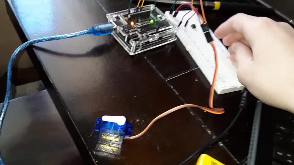
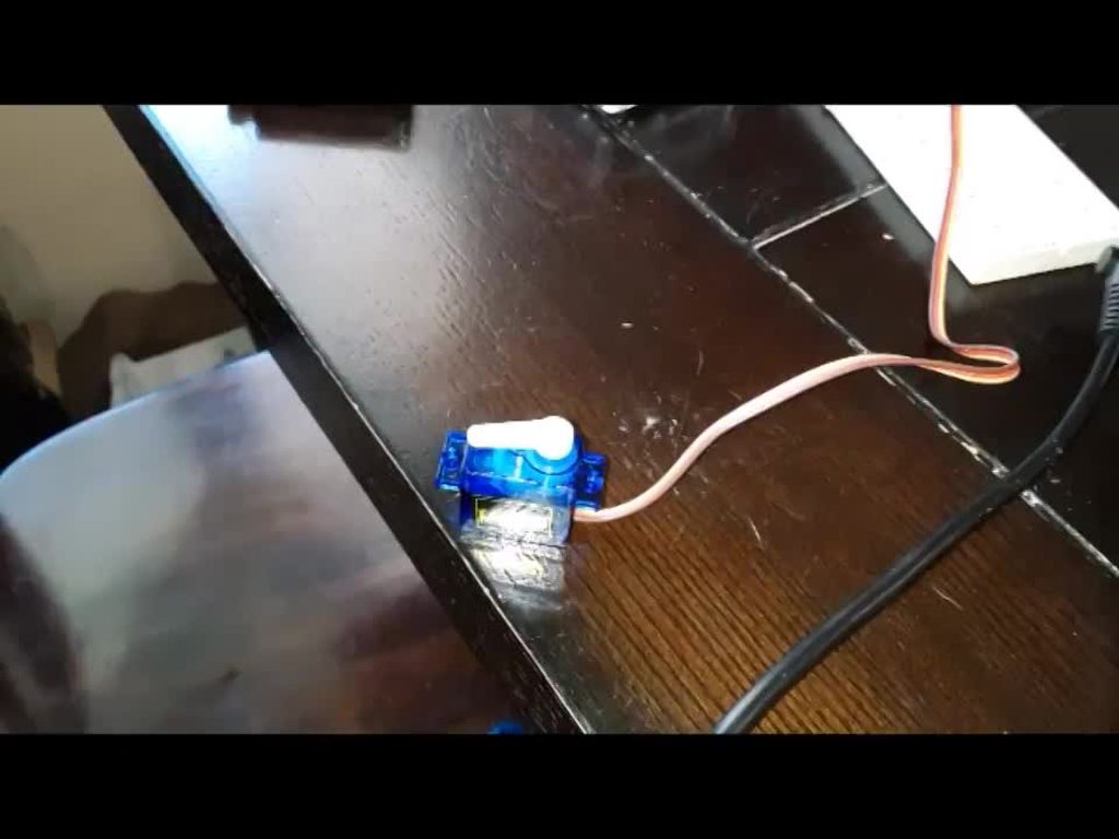
My server works fine when my arduino is connected via USB but when using battery power it only moves like 1 degree every time I press the button
With USB: https://imgur.com/v0ukXbC
Without USB: https://imgur.com/Eq5SHH3
Full Code: https://pastebin.com/5dxBNVZJ
pine bramble
is your battery dead
old heart
I don't think so, but I'll check
old heart
It seems like it's resetting the arduino whenever I push the button
Only when it's not connected with USB
old heart
The battery is not dead
I was reading about it and it seems that it might be draining too much of the battery at once, and that causes the Arduino to reset
pine bramble
You could try a BFC (large electrolytic capacitor) to hold up the power supply, but you might just need a bigger battery (or both a bigger battery and a BFC). @old heart
old heart
ok thank you!
 forest venture
Hi, I have this code: https://hastebin.com/pecosemoqe.cpp
My arduino doesnt turn off the light, but ALWAYS turns it on. It looks like it's crashing on the end part. It works on another arduino. I'm aware of the fact I reset the arduino every second, this was a test to see if that worked.
forest venture
^? 😄
barren scaffold
Add extra print statements in that if statement in slowTimer()? Will need bracing to make that work, but helps verify you have the logic and variables set the way you think you do.
Or in the on() and off() functions. Same difference in that particular case.
pine bramble
  Serial.begin(9600);
  mcp.begin();                  // use default address 0
  Wire.begin(8);                // join i2c bus with address #8
  Wire.onReceive(receiveData);  // register event for receieving data over i2c
  Wire.onRequest(sendData);     // register event for sending data over i2c
  Serial.println("ready!");
  Setup.massPinMode(fixtureArray, OUTPUT);
  Setup.massDigitalWrite(fixtureArray, sizeof fixtureArray, HIGH);
}```
my setup never gets to `ready!` is there anything that stands out in this as to why?If you add more print statements around each line, can narrow it down to a particular line failing (grandpa's debugging method from when there weren't better accessible tools).
pine bramble
putting it right after .begin still doesn't output any serial data. hmm
barren scaffold
Right after mcp.begin() or Serial.begin()? If the latter, you might not have USB serial working right.
pine bramble
right after serial.begin
this is via pi cli tool called ino so that is a possibility. i'll try on windows and report back
it uses picocom for serial
barren scaffold
Can add something else like turning on an LED right before or after the Serial.begin(). Point being, how many ways can you get feedback on which lines execute, and which ones are never reached?
north stream
You may need to wait for Serial to initialize before calling begin()
forest venture
Well, when I restart the arduino it's working fine
so I think my arduino is freezing
 bleak badge
Hey guys !
I'm looking for some help with getting my arduino mega working with an ESP8266 01 chip ..
I had made a fully working distance sensor with arduino MEGA, network shield and a HC-SR04 sensor, but then found that there's no way I can get ethernet cable to the installation spot.. So ordered an ESP8266 01 and now trying to convert the thing.. but not getting any success.. my knowledge simply is insufficient and online articles seem to be very contradictory.
the working code (for use with ethernet shield) is here
I've used this article as base to work off for the conversion (wiring and code)

ThingsBoard
ThingsBoard IoT Platform sample for temperature data upload over MQTT using Arduino UNO, ESP8266 and DHT22 sensor.
but all I'm getting is time outs and shield not found using following code
https://pastebin.com/QTFTu1fW

Pastebin
 coral geyser
hi, any ideas why the serial monitor might stop sending or receiving stuff after a while?
if i try to send stuff anyways a few times, the only way to interact with the arduino environment left is the task manager... (unless i unplug the usb cable to the feather 32u4 i'm using)
it doesn't even say the usual text "no response" (or so.. i'm german, so i am not sure right now how to translate "keine rückmeldung" correctly)
it only happens when i use the fonaserial together with the tinygps+ library. the goal is to send gps coordinates via sms
currently i still think it isn't necessarily a problem with my coding logic though
i can provide the parts i believe to be critical if needed
pine bramble
adding something before serial.begin doesn't execute either. uploading via windows now as well
massively simplifying my code at least will allow the first serial.print after serial.begin to work but nothing after mcp.begin will work
pine bramble
only way it gets past is if i remove my i2c data/clock wires
 quick lodge
have you tried a SoftwareSerial library to troubleshoot? @pine bramble
pine bramble
think maybe one of my i2c lines was crossed going to a slave device...whoops
barren scaffold
@coral geyser to eliminate if it might be the serial monitor, you could try something else that can talk serial. Maybe PuTTY. Going to see how that works on my PyPortal.
pine bramble
hmm, nope. having the 2nd i2c device on that bus is definitely the issue though
barren scaffold
PuTTY does work as a serial monitor. Pointed it at COM3, 9600 bps, worked fine. May make that my long-term logging option. Your COM port may vary.
 crisp talon
hi out of pure curiosity does anyone know the current output for each i/o pin on the adafruit trinket mini
?
north stream
Not very much (from page 950 of the MPU datasheet)
crisp talon
thank you but which pins of the adafruit tinket mini microcontroller (I didn't specify that last part I don't know if that makes a difference) are which from that image?
north stream
That's for the Trinket M0, I think the older ATtiny based Trinket would be different.
That should refer to the normal I/O pins, however I2C pins might be different.
crisp talon
wait so would the trinket mini micro controller be similar to the trinket m0?
north stream
Hmm, let me look. Looks like the "mini" is the ATtiny based one.
crisp talon
do you know or at least know where I could find the equivalent information for the mini?
crisp talon
awesome!
so would that be for any of the i/o pins?
north stream
Looks like it
north stream
There's a 3V mini and a 5V mini, I think all the pins give the supply voltage on both
crisp talon
sorry final question on the 5v version i know the usb pin gives off 500 mA but what does the bat pin give off?
north stream
Depends on the battery hooked up to it. With the little LiPoly cells, you can probably get 10C out of them safely for brief periods.
I just pulled up the data sheet for the 500mAh one: it specifies 1C continuous discharge rate, so no more than 500mA for an extended time. If you want higher current, choose a larger cell.
coral geyser
@barren scaffold so.. i installed putty but nothing happens when i click "open"... only the typical windows error sound is being produced..
changed the port from com1 to com3 (yes, i'm also using that one) already but i can't figure out what else is important to make it run..
anyway, since many orher sketches run without problem on the serial monitor, i believe the problem shouldn't be there
oh, one more thing.
i also let it run on the vscode extension for arduino, and there the exact same problem apperead with neither being able to receive, nor send data after a while
coral geyser
no idea what i did, maybe i used listen() in the correct order now at the right places, but i only get "failed" when i try to send the sms now
well.. it still stops working shortly after i try to send the sms... on the right is the most critical part of the code
coral geyser
next info, it only happens when the sim card is unlocked
while it is locked everything else works fine
barren scaffold
@coral geyser don't know offhand. Assumed you were just hanging the serial monitor.
coral geyser
ok then
what else might be useful information for you to figure something out?
barren scaffold
Not sure. I don't arduino a great deal. All I normally recommend is to keep cutting things out until the bare minimum amount of code is left to reproduce the problem, and then it makes it easier for someone to investigate.
pine bramble
so i've narrowed down having my pi on the i2c bus along with my MCP23017 (both with different addresses) causes my program to halt setting up serial with the MCP. what could be causing this? it worked before with just the pi and vise versa with just the MCP. the circuit is the data lines and the clock lines all connected together and ran to A4/A5.
 hazy wadi
good day all 😃 . im using XOD ide and according to the google gods Adafruit made the library for the PN532 nfc/rfid readers . its said they use i2c to communicate but the nodes state IRQ as inputs, was wandering if anyone here new witch is correct ?
north stream
I'm guessing it uses I2C for communication and IRQ as a "wakeup" signal.
@coral geyser Sounds like a timing/network issue when sending the SMS?
hazy wadi
@north stream are that would make sense ill try it out see what happens 😃
north stream
@pine bramble I'm unclear on what you're saying. What are the peripherals? You said "just the pi" (which implies no peripherals) and "just the MCP" (which I don't understand).
coral geyser
ok, but how can i find that issue?
right now i reduced the code to what is necessary (i think) for reproducing the problem and sure enough it appeared again. the whole arduino ide died off again while using the serial monitor.
but only the visual stuff apparently. spammed away some stuff like ctrl+u or ctrl+q and as i unplugged the feather all these commands were executed at once.
the output looks certainly interesting..
ah, and the orange lamp turns off completely after i do that.
only after reopening the ide and replugging the feather the lamp turns on again
something seems to be definitely breaking the board the way i use the code...
north stream
I'm guessing either the GSM board is getting an error, or the processor is having a serial issue (how many serial ports are you using? Are you using software serial?), it's running out of memory, or a power supply brownout.
coral geyser
hm..
what ways would i have to fix the gsm module?
not sure.. the one from usb, pin 10&11 for gps (NEO6M7M GPS from ublox), and then the fona antenna
so.. three..?
yes, i'm using software serial.
what memory exactly? in this condensed sketch it uses only about 9k Bytes of flash and still breaks down :/
power supply shouldn't be it either; i'm using the lipoly accumulator which is suggested on the website
north stream
I'm thinking RAM, not flash. The Fona library eats up a lot of storage.
coral geyser
and i just tested, in the condensed version it runs freely when i enter a wrong pin for the sim card, so it doesn't unlock
ok, how can i check that?
pine bramble
@north stream i have both of those devices connected on an i2c bus. my code does not run correctly like that. if i remove one it works fine.
north stream
Both devices are a pi and the MCP?
pine bramble
yes
i've seen some people say put a 4.7k ohm resistor on both lines to 5v but i don't think i have any that value, only 10k
coral geyser
thx for the link, now i know it isn't the memory
i kept sending the free memory in the loop; with locked sim card it would go on without a break, with unlocked sim it goes on for about a minute and then stops.
the values for free memory printed are exactly the same
@north stream
north stream
Seems like something's going awry when it tries to send the SMS and it doesn't work.
coral geyser
i don't even try to send the sms yet
 burnt island
@pine bramble what voltage are you powering the MCP with? Do you have a level shifter in the mix? What's the 3rd component? MCP, Pi, and what?
pine bramble
an arduino. MCP is powered with 5v from the arduino
burnt island
The Pi is a 3.3V device, so having it on the bus may be dragging the voltage down below the level the MCP needs to reliably communicate. The Pi probably doesn't like the 5V on it's i2c pins either
coral geyser
the line of numbers down there goes on for up to ten "meters" i think and then just ends.
only because i unlock the sim card
if i don't, i could wait probably many hours until the line ends because of overheating or whatever
pine bramble
@burnt island ok that makes sense why it works with only one i2c device, regardless of which one that is.
so level shift the i2c lines to the pi down to 3.3v or find a different way to communicate with my pi sounds like the fix
burnt island
yup. Level shifters are dirt cheap
pine bramble
like this one? https://www.adafruit.com/product/757

Because the Arduino (and Basic Stamp) are 5V devices, and most modern sensors, displays, flash cards and modes are 3.3V-only, many makers find that they need to perform level ...
burnt island
yup
 dark ravine
hey guys, new to this discord. i was wodering what are some of the best books or video series to learn arduino with.
pine bramble
boy this is getting really old having code that compiles but never gets past setup()
north stream
Which CPU?
pine bramble
whatever the uno has
i can only simplify my code so far before its just a hello world lol
north stream
I've had a couple of issues waiting for Serial to initialize, but on a Uno that shouldn't be an issue.
My next step is LED debugging: blink the LED once, then do something, then blink it twice, etc. Even if serial doesn't work, that should let you see how far you got.
pine bramble
yea all my outputs are via the MCP and my wiring is a rats nest so i really don't want to be changing my circuit that much to debug. also have no LED's only relays i guess i could use that
north stream
The Uno should have a built-in LED: that's the one I tend to use for such tricks.
pine bramble
but even then, knowing what line it stops on doesn't help me much. i'm pretty sure its stopping at mcp.begin();. ...why that is is anybodies guess
north stream
That's the beauty of open source: if necessary, you can just grab the MCP library code and run it directly, sprinkling in debug statements (Serial, LED, whatever works). I've done this more than once when chasing persistent arcane issues.
I'll admit to more than once narrowing it down to a specific line of code and just staring at it wondering WHY???
pine bramble
now i'm just getting intermittent serial
i'm about 5 minutes from throwing all this in the garbage lol
north stream
Intermittent? That's annoying, but probably also a clue.
pine bramble
now it gets to ready! and stops
last upload it ran loop 1.5times then hung
i really don't want to have to start over completely and test after every line of code and every wire ran but at this point developing on this seems like the only way to ensure you don't waste hours of assembly and coding just to get odd behavior you can't debug
i'm assuming this is an i2c issue. why the wire library decides: hey, i'll just try this over and over and over and block your code with no hint as of why! nobody knows....
north stream
What do you have connected to pin 18?
pine bramble
there is no pin 18
north stream
The MCP23017 should be a 28-pin IC. It ought to have a pin 18.
pine bramble
10k ohm resistor to 5v
guess i'm gonna try to throw some 10k ohm resistors on the data/clock lines. beyond that idk what to try
north stream
You could try paralleling 10k resistors from the clock and data lines to 5V, that would give 5k, which might work better than 10k.
pine bramble
how would that go? sorry noob to circuits here
pine bramble
adding pinMode(A4, INPUT_PULLUP); pinMode(A5, INPUT_PULLUP); before mcp.begin ran and looped 4x before it halted
 winter crypt
anyone have any pointers on having a function happen once I supply power to my motor control board? trying to have a motor turn on for a set amount of time once it receives power.
iron monolith
I honestly do not know. I could look it up? Unless you have tried and haven't found anything.
winter crypt
I havent found much about it, only stuff I have found talks about using the I/O ports as a reference, but didnt provide any sort of example.
iron monolith
The Arduino programming language Reference, organized into Functions, Variable and Constant, and Structure keywords.
Here is Arduino's references for functions, libraries, etc.
winter crypt
so something like an analog read of the pin that turns the motor on at a specific threshold value could work?
int analogPin = A1;
int val = 0;
void setup() {
Serial . begin(9600);
}
void loop() {
val = analogRead(analogPin);
followed by some if statments?
iron monolith
I do not know Arduinos the best. Some other users can help.
winter crypt
thanks for the help though!
iron monolith
No problem! I'm in the process of learning Arduino still so I wouldn't be your best pick. 😁
 ancient mica
Is that an elegoo Arduino uno kit?
old heart
yea
ancient mica
The instructions have a 10k potentiometer to control the contrast, no other resistive components
north stream
I think the backlight has an internal resistor, you just give it 5V.
old heart
ok thank you!
bleak badge
anyone who can take a look at my code ? it gets verilied fine but doesnt seem to work once on the arduino..
pine bramble
Code for what exactly?
bleak badge
@pine bramble I'm trying to send sensor data over arduino mega and esp8266-01 to my mqtt server
at commands work fine, but when I use the s,ippets of code I find on the net I get shield not found..
north stream
You may need to adapt the code to match the pinouts of your hardware?
bleak badge
I have the esp connected to pins 2 and 3 (tried both ways) but no go ..
north stream
Hmm, serial port is usually pins 0 and 1.
bleak badge
north stream
Ah, you're using software serial on pins 2 and 3, but you're calling WiFi.init() on Serial1 instead of your software serial instance.
bleak badge
I have no idea what you just said :p
north stream
Try changing line 26 to ```c
WiFi.init(&soft);
You probably will also need a line like ```c
soft.begin(115200);
Alternatively, instead of pins 2 and 3, you could just move the ESP to the pins that Serial1 uses.
bleak badge
0 and 1 ?
north stream
0 and 1 are Serial, I think, and you're already using those for debugging. However, the code initializes Serial1 as well, and is trying to use it to talk to WiFi.
bleak badge
I have serial monitor also, doesnt that interfere ?
north stream
The Mega has multiple serial ports, so it can do both at once. You'd just need to move your ESP to the Serial1 pins (I think they're 18 for TX and 19 for RX).
bleak badge
you brilliant stranger :p
north stream
I'm guessing you tested out your AT commands with the software serial connection on pins 2 and 3. On an ordinary Arduino which only has one serial port, that's the usual approach. But on a Mega, which has another built-in hardware serial port, you can just use it instead and not bother with software serial.
bleak badge
it works 😃
I'll try figuring the mqtt stuff out by myself and if need be I'll be back 😉
thanks again.. you saved me from tossing the lot into the bin out of frustration 😋
north stream
It's hard, having invisible things happening and not knowing what's going on or even how to figure it out.
 tacit otter
hi everyone, i have a problem with the GrandCentral and my MacOS 10.14.4. I seen this problem in the git https://tinyurl.com/y43gsxwu , but when i update the uf2 to 3.3.0 , the board resent itself during the download of the code in the Arduino IDE.

GitHub
MSC bootloader (based on UF2) for SAMD21. Contribute to adafruit/uf2-samdx1 development by creating an account on GitHub.
tacit otter
i tried to upload the CircuitPython 4.0.0-beta.7 but the usb stay "GCM4BOOT" and not become "CIRCUITPY"
 sour tide
@tacit otter please file an issue on the github repo. other folks will see it there
tacit otter
GitHub
Hi everyone, i have a problem with the GrandCentral and my MacOS 10.14.4. I seen this problem in the git https://tinyurl.com/y43gsxwu , but when i update the uf2 to 3.3.0 , the board resent itself ...
 stark moss
I am working on a project with a 7 segment display and a count down timer. I have gotten the time to work, but now I am trying to get it to start when I push a button. Right now, the function running the countdown timer appears to start when the arduino starts, but the numbers don't show up on the screen until I push the button. The problem is when I push the button the count down is already partially through or completely over. I have put my code in a paste bin. Could anyone help me figure out what is going on?
https://pastebin.com/RiDGKUJs
bleak badge
got my esp8266-01 working with arduino mega and mqtt working, but every x seconds I get this
[WiFiEsp] TIMEOUT: 2
it reconnects fine but i'd like to get rid of this
@north stream .. you still here ? :p
north stream
@stark moss How is your button wired? The usual setup is to wire the button to ground and set the pinMode to INPUT_PULLUP then check for LOW to detect the button pressed. You might also want to add displayNumber(0) in setup().
stark moss
I had the button wired to ground originally, then switched it to 5V and changed the code to what I have, then just now changed it back to ground and updated the code to what you said. The button press is being read. The screen lights up only when the button is pushed. The problem is the countdown timer is running in the background wether the button is ever pushed or not.
The timer also does not restart if you push the button again which I would expect.
north stream
You'll need more logic to make it do that.
old heart
Why does
#include <LiquidCrystal.h>

String input = "";

LiquidCrystal lcd(7, 8, 9, 10, 11, 12);

void setup() {
  lcd.begin(16, 2);
  Serial.begin(38400);
}

void loop() {
  if(Serial.available() > 0) { // Checks whether data is comming from the serial port
    input = Serial.readString(); // Reads the data from the serial port
    Serial.println(input);
    lcd.print(input);
 }
}```
print "⸮⸮⸮"?I send "H"
barren scaffold
You type H, you get back ⸮⸮⸮ ?
old heart
yes
barren scaffold
On both LCD and serial?
barren scaffold
So different non-H characters.
barren scaffold
No idea yet. If you print a simple string variable over Serial or LCD during setup() does it show up correctly?
old heart
Let me check
hmm
i get "⸮⸮" when i send "Hello" from startup on serial
but LCD works
barren scaffold
First thing I'd check is if there's a mismatch in serial speed. Never used a Bluetooth setup for that, but old-school original serial had to match up perfectly on both ends.
old heart
Well im using Serial.begin(38400); for the bluetooth
barren scaffold
Mismatch would garble data in both directions. So no guarantee that H goes correctly, or that what it thinks it read got repeated correctly.
old heart
Ok
barren scaffold
Maybe it'll work out of the box at 9600 instead of 38400. No idea how that Bluetooth part of the chain works.
old heart
Yea it sends "Hello" with Serial.begin(9600);
hmm
I've used bluetooth before and never had this problem
barren scaffold
Then your Bluetooth isn't talking at 38400. Might be configurable to do that, but I'm guessing if you pick anything other than 9600, it will fail. (4800, 19200, 2400, 1200, ...)
old heart
I'll double check everything, Thank you!
old heart
I managed to get it working, :D Edit: Well kinda
old heart
Well now i have another problem, How do i read from the serial with this?
#include <SoftwareSerial.h>
#include <LiquidCrystal.h>

LiquidCrystal lcd(7, 8, 9, 10, 11, 12);
SoftwareSerial Bluetooth(2, 3); // RX | TX

String input;

void setup() {
  Serial.begin(9600);
  Bluetooth.begin(9600);

  lcd.begin(16, 2);
  Serial.println("The bluetooth gates are open.\n Connect to HC-05 from any other bluetooth device with 1234 as pairing key!.");
}

void loop() {

  if (Bluetooth.available()) {
    Serial.write(Bluetooth.read());
  }

  // Feed all data from termial to bluetooth
  if (Serial.available()) {
    Bluetooth.write(Serial.read());
  }
}```It prints the msg onto the Serial monitor but how do i read it from there?
Serial.read() and Serial.readString() return random numbers
old heart
It uses Serial.write() to send stuff to the serial monitor, how do i receive that and put it in a variable?
old heart
I can send stuff to the serial monitor i just don't know how to put that thing into a var
burnt island
which stuff are you trying to save?
 long sphinx
Anyone have a good tutorial for converting bmp's to epaper compatible 1bpp bmps?
 inland crag
Use imagemagick
convert inputfile.bmp -depth 1 gray: outputfile.bmp
thx
 waxen coral
Hi! Is there someone here who has worked with MIDI on the Arduino? I'm trying to build a MIDI-controller. I can send data in to the computer without a problem, same goes for data out from the computer. But when I connect both MIDI in and MIDI out cables to the computer the MIDI monitor (MIDI-OX) goes crazy and continuously spam note on/note off messages. Anyone who knows why this might happen?
#include <MIDI.h>

int LED = 10;

MIDI_CREATE_DEFAULT_INSTANCE();

void handleNoteOn(byte channel, byte pitch, byte velocity)
{
  digitalWrite(LED, HIGH);
}

void handleNoteOff(byte channel, byte pitch, byte velocity)
{
  digitalWrite(LED, LOW);
}

void setup()
{
  MIDI.begin(MIDI_CHANNEL_OMNI);
  pinMode(LED, OUTPUT);
  MIDI.setHandleNoteOn(handleNoteOn);
  MIDI.setHandleNoteOff(handleNoteOff);


}

void loop()
{
  MIDI.read();
}
 vast cosmos
hi, i have a little board that has 6 infrared sensors around the outer edge, each with digital and analog pins. the intent is to poll these analog pins to determine the direction from which an IR signal is being transmitted. docs for this IR board say it needs 5V power, but i have it wired up to a Adafruit Hallowing M0 i received in a past adabox, which only has a 3V (regulated) output. i've ordered a logic level shifter, but in the mean time i'm powering the hallowing over USB and then supplying power to the IR board from the pin labeled "USB" (on the feather M0 pinout diagram). i've verified with my multimeter that the IR board is in fact pulling 5V from this hallowing pin, so I think i'm supplying power to this board sufficiently
the problem i'm having is reading the analog voltage from any one of these IR analog inputs wired into either A0 or A1 on the hallowing. reading the analog signal from pins A2-A5 work as expected, so its something specific to A0 and A1. i'm using arduino BTW and would happily draw diagrams or paste source code if necessary, but i suspect im overlooking something fundamental as i'm very (very) new to electronics
the "problem" im having is that the analog reading from A0 and A1 is always the same, regardless if IR light is being received by the diodes or not. the other IR sensors (separated by a few centimeters) range in voltage from 0-1023 (10 bits) depending on if I shine IR light on them or not, which is what i would expect from -all- analog pins A0-A5 on the hallowing, not just A2-A5
(hope this is the right channel to be asking...)
barren scaffold
@vast cosmos as good a channel as any, but response times can vary. If it's https://www.adafruit.com/product/3900 , then by default, A0 is a speaker, A1 is a light sensor, and A2-5 are for capacitance. Are you doing anything in particular to set A0 and A1 in your setup() as generic inputs?
This is Hallowing..this is Hallowing... Hallowing! Hallowing! Are you the kind of person who doesn't like taking down the skeletons and spiders until after January? Well, we've ...
 untold vapor
Hey all, I'm running into some issues with a 32u4 with avrdude. I was able to upload a sketch via the arduino IDE, however I am looking to upload a C program to run via avrdude. I am reading online about having to sink the RST line 2 times within 750 ms in order to get the chip into a state to upload. Can someone give me some more information on this? I am currently running the command: avrudude -p m32ur -P /dev/ttyACM0 -c avr109 -t and the command is timing out. I am just trying to get into terminal mode in order to see if I can contact the board. Using Ubuntu 18.10.
I followed this guide, https://www.pololu.com/docs/0J61/10.2 however I am still unable to connect to the avr
User’s manual for the Pololu A-Star 32U4 family of user-programmable boards.
untold vapor
I have also tried using the Arduino IDE on ubuntu/windows. Windows can upload a sketch to the 32u4 however when I try on linux with the same board settings (only thing changed is the Port) it fails due to signature mismatch
Received the following error:
Connecting to programmer: .
Found programmer: Id = "CATERIN"; type = S
    Software Version = 1.0; No Hardware Version given.
Programmer supports auto addr increment.
Programmer supports buffered memory access with buffersize=128 bytes.

Programmer supports the following devices:
    Device code: 0x44

avrdude: devcode selected: 0x44
avrdude: AVR device initialized and ready to accept instructions

Reading | ################################################## | 100% 0.19s

avrdude: Device signature = 0x0d3f0d
avrdude: Expected signature for ATmega32U4 is 1E 95 87
         Double check chip, or use -F to override this check.

avrdude done.  Thank you.
@barren scaffold nope, i'm not invoking pinMode or anything like that. i'm just using analogRead() without any preparation on the pins
arduino's pinMode(), that is
barren scaffold
I could misunderstand, but without pinMode or something similar, what makes A1 suitable for your IR sensor instead of its default visible light setting and sensor?
pine bramble
@untold vapor /dev/ttyACM0 is USB
vast cosmos
A0-A5 are wired up to a separate array of IR light sensors that need to be arranged in a very particular physical configuration around the circumference of a circle
barren scaffold
And you've bypassed any hardware already on the board connected to A0 and A1.
untold vapor
@pine bramble What do you mean by this? I was able to upload a blink sketch to an arduino uno on /dev/ttyACM0
Just not the leonardo
pine bramble
@untold vapor Let's take this to #general-tech for a bit so these folks can discuss what they are already discussing. ;)
vast cosmos
@barren scaffold thats what i would like to do as i need to use a different board's sensors
barren scaffold
I mean you've physically cut out or otherwise disconnected the light sensor on A1? I'm not strong on the physical side of electronics, but that's what jumps out at me. A2-A5 as just bare contacts, but A0 and especially A1 connected to other hardware.
Assuming I've seen the right board.
vast cosmos
@barren scaffold but ill brb, gotta run out for 30 mins and will read anything you write when i return
barren scaffold
I'm mostly the rubber duck for rubber duck debugging around here.
vast cosmos
@barren scaffold well that's one problem, the adafruit docs on the pinout for the hallowing leave a lot to be desired. they say: "Right now you can use the Hallowing just like a Feather M0 Express, it's got the same chip although the pins have been rearranged", but they don't ever say how or what has been rearranged. the graphical pinout for the hallowing does not specifically label any analog inputs other than A2-A5, and those are only called out because they connected to the capacitive touch pads
they don't label any of the analog pins on the header socket
i am curious where you are getting your pinout info from though, i dont see where you know A1 is connected to the built-in lux sensor
but no, i have no physically cut a trace to A1. i'm trying to ignore and not use the built-in light sensor (the one you claim is pinned out to A1), which would certainly explain this conflict i seem to be having
pine bramble
Pinouts are from the Schematic (most authorative, when offered) and from the code base (Arduino IDE) and from a special pinout diagram .. and from the 'pinout' section of a tutorial that is linked on the product page.
vast cosmos
i just need 6 analog inputs on the hallowing for my own analog sensor data im supplying. i thought i could use all of A0 - A5, but I can only read A2 - A5. reading from A0 and A1 always returns the same value regardless of the analog signal im inputting into those ports
pine bramble
vast cosmos
@pine bramble oh i didn't think about the schematic shown at the bottom of the product page. i've been leaning on the pretty/colorful diagram someone made
wonderful, thanks @pine bramble
barren scaffold
@vast cosmos been asleep for a bit. I linked a product page for what I assumed you were using in my first reply, and saw where the analog pins were on the PCB.
pine bramble
A1 connects to the light sensor and A0 connects to the audio amp.
vast cosmos
@barren scaffold yep, you linked the correct product. my problem was the particular diagram i was using as pinout reference
my mistake
pine bramble
I heard Tony DiCola once make a casual remark about the schematic being the most authorative source, and have used that notion ever since (look at the schematic, first).
If you order a pizza with a bunch of different toppings on it, it's going to arrive .. with a bunch of different toppings on it. :)
The Hallowing is specific to a kind of project where it is desirable to have those pins allocated the way they've done it.
It's like getting anchovies on purpose. ;)
vast cosmos
gross
but yes, it looks like the hallowing may simply be inappropriate for what I'm attempting
pine bramble
If you can deal with no light sensor and no audio amp you could cut the trace (if you can find it) but then connecting to those port pins may still be difficult to achieve, mechanically.
vast cosmos
the analog pins i'm using succesfully (A2-A5) are intended for reading the capacitive touch pads on the hallowing, but when i plug my own analog sensor into them as input, they function as expected. what i dont understand is why A0 and A1 wouldn't also function as expected
pine bramble
The amplifier might possibly have a disable line that lowers the effect it has on that port pin of the micro.
vast cosmos
i think my confusiong is that i didn't need to cut the trace to the capacitive touch pads, and i was still able to use those pins as external analog inputs
pine bramble
A2-A5 use internal capabilities of ATSAMD21G18A for capactive touch input. Those 'fangs' are just pads (circuit board copper foil).
vast cosmos
my confusion*
pine bramble
Whereas A0 and A1 are electrically wired to devices onboard the Hallowing.
That'll futz with the use of those port pins as ADC.
vast cosmos
i just ordered a pair of trinket M0s and one itsybitsy M4 that will arrive on tuesday (along with some 8-channel bidirectional logic level converters) since this goofy IR array module i'm trying to use if 5V and all of adafruits cool little boards are 3V
pine bramble
I think the level converters require that all lines on those chips are properly terminated (if you aren't using them all).
vast cosmos
im hoping the itsybitsy M4's analog inputs arent going to be ...prohibitively feature-full like this hallowing. whereas the trinkets simply dont have enough analog input pins, but they were too adorable to not purchase
pine bramble
Can make breadboarding them a bit more complex to achieve. ;)
ItsyBitsy M4 iirc has nothing on the board except the MCU. Maybe something or other that doesn't matter here.
Looks like it's got dotstar, qspi flashROM and a single channel level shifter 74HCT125.
vast cosmos
well you guys are being more helpful than i ever could have hoped. perhaps you could give me your suggestions or opinions -- im very new to electronics, brand new in fact. the IR board im trying to use is the following: https://www.robotshop.com/en/ir-follower-module.html

100% Arduino Compatible
Can be used to build a light following robot
Consists of 6 IR diodes
This IR Follower module can be used to sense infrared light as a way to guide your Arduino project
however, i also purchased a fistful of simple IR sensor diodes so that i could construct an equivalent module like this myself. im curious if i should keep struggling down the path of integrating this separate board or just wire up the IR sensors i already have directly
i originally purchased some IR sensors that have built-in filtering and demodulation, so there was no way to get any sort of analog sensing capability -- it either received a signal or it didnt. those proved the wrong sensor for the job of detecting the direction of an infrared transmission source
barren scaffold
If all you’re doing with that board is getting analog out from your diodes, then it’s just a convenient carrier board. I’d use it as long as the sensor arrangement was convenient.
vast cosmos
the arrangement seems convenient, intuitively speaking, but it will take some prototyping to know for sure. my only concern is their proximity to each other, they seem too close to have any confidence that the diode receiving the strongest signal -REALLY-IS- the one nearest the transmitter (and thus the direction from which the transmitter is transmitting)
if that makes sense
barren scaffold
Would have to test. If the ADC resolution is good enough and the diodes are all identical, should work.
If the IR source is in the same plane as the diodes, then the furthest will be in the shadow of the closest, and should be easier. If not, you’re relying on small differences in distance from the source to each diode. Could still work.
vast cosmos
i'm hoping so 😃
so until my ItsyBitsy M4 (and logic level converters) comes in on tuesday, i'm stuck working with what i've got. in particular, i moved the arduino code off of the hallowing onto one of my circuit playground express (CPX). however, the CPX itself doesnt have a way to accept 5V inputs
is there some safe way i can create a level converter? i have a voltage regulator that has a little trimpot on top for adjusting output voltage and an output voltage readout on a built-in 7-segment display
is that sufficient? would an adjustable voltage regulator do the same thing as a logic level converter?
well never mind, the regulator only has a single VIN+/- and a single VOUT +/-. i reckon i need something for handling all 6 analog signals output from the IR board before they reach the CPX analog input pads
 stable forge
@vast cosmos if this is just an input, you can use a voltage divider: two resistors. Just finding a good writeup for you.
vast cosmos
it is. a 5V-powered board has 6 analog output pins i'm trying to read using an adafruit circuit playground express
unfortunately im very new to electronics and do not have a reasonable collection of resistors
stable forge
https://electronics.stackexchange.com/questions/231616/can-i-use-a-voltage-divider-for-shifing-logic-levels and man yothers. You could test with just one output and see if it looks OK.
vast cosmos
10k, 220, and 560 ohm are my only options
stable forge
well, you want to get 2/3 of 5v, so just use three 10k's in series, and tap at the first one
vast cosmos
hmm, it looks like i didn't order the 8-channel shifter i thought i ordered. instead i picked up 3 of these: https://www.adafruit.com/product/757
Because the Arduino (and Basic Stamp) are 5V devices, and most modern sensors, displays, flash cards and modes are 3.3V-only, many makers find that they need to perform level ...
and since i have 6 inputs, that's gonna be annoying to have to use 2 of those
(if that's how those work)
stable forge
vast cosmos
i should have ordered the 8-channel shifter: https://www.adafruit.com/product/395

Because the Arduino (and Basic Stamp) are 5V devices, and most modern sensors, displays, flash cards and modes are 3.3V-only, many makers find that they need to perform level ...
im sorry @stable forge, i cant emphasize how ignorant i am with circuits and electricity in general, i appreicate the help though, its just over my head
stable forge
I'm not sure these level shifters are linear enough for your analog outputs.
vast cosmos
i need recommendations on a good intro to electronics and circuits book
vast cosmos
"linear enough"? are you referring to time?
stable forge
the output is analog. The level shifters are often meant for digital signals. You want a smooth conversion of any voltage 0-5V to 0-3.3v. The resistors will do that. What board is producing the 0-5V output?
vast cosmos
100% Arduino Compatible
Can be used to build a light following robot
Consists of 6 IR diodes
This IR Follower module can be used to sense infrared light as a way to guide your Arduino project
im thinking about ditching this board though. i have plenty of IR receiver diodes i can wire up directly. i thought this board would be convenient
stable forge
do you really want analog inputs, or just detection?
it's possible the board will work at 3.3V instead of 5V
vast cosmos
really need analog input. we need a way to determine the direction from which an IR signal is being transmitted
its more difficult to do that if you only have discrete digital signals
i was originally using IR sensors that do filtering (for standard IR protocol frequencies) and demodulation, so it was practically impossible to determine which IR sensor received a signal first or which had the stronger signal. analog makes that problem easier to tackle, as far i can tell
stable forge
schematic is here: https://osepp.com/downloads/pdf/IR-FOLLOWER.pdf. The analog outputs are just a tap on a voltage divider with one fixed resistor and the photodiode. The rest of the stuff is for digital output
you wouldn't be using 90% of the circuitry
vast cosmos
so ditch the board and use the IR diodes i have directly
pine bramble
That thing is LM393D based so you can go down to 2.0 volts on Vcc.
stable forge
yeah. @pine bramble ardnew wants the analog outputs so the op amps won't even be used. The only voltage restriction is that the blue LED's won't function below like 3V, but they are just for status, it appears
pine bramble
danh I was wondering if the ir sensors would operate at 3.3 volts .. haven't figured that out. ;)
vast cosmos
i was just about to point out those blue LEDs are pretty handy. but if i wire my IR diodes to a circuit playground express, (basically the same circular shape), i can use its neopixels for the same purpose, and have the added benefit of mulit-colored status for strength-of-signal or something else perhaps
stable forge
datasheet for the IR photodiodes, https://osepp.com/downloads/pdf/UPT333C-datasheet.pdf
pine bramble
Yeah I really don't know what those are. ;) I think Adafruit may have something similar in their catalog.
stable forge
@vast cosmos I think you'd want to calibrate your application. So just try a resistor and a photodiode and see whether you get the sensitivity you want. Try the 220 and the 560 ohm reiistors you have
vast cosmos
i'll have to break down my current wiring and reorganize a bit, as what little number of devices im currently using are getting a bit overwhelming. i'll try using the diodes and toss this board in the morning
stable forge
I need to 💤 but good luck!
stable forge
but the prod description makes it sound like they have an IR blocking filter
descriiption says _Basically, connect the pin connected to the 'thicker' part of the sensor to 3-15VDC or so, and the thinner-part pin through a ~1K-10K series resistor to ground. _
vast cosmos
i originally purchased these: https://www.adafruit.com/product/157 and soon realized they were waaaay to helpful to be useful for my application

IR sensor tuned to 38KHz, perfect for receiving commands from a TV remote control. Runs at 3V to 5V so it's great for any microcontroller.To use, connect pin 3 (all the way to the right) ...
stable forge
Built-in optical filter for spectral response similar to that of the human
eye for the 2831
vast cosmos
thanks again, rest assured i'll be back tomorrow with more naive questions to ill-phrased questions
stable forge
questions are good - they are how you learn! good night!
 gleaming fractal
Howdy folks, I just received a Feather 328p board and the CHG yellow LED is flashing like crazy, with out anything plugged in. Then when I plug in a 400mAh LiPo it just goes off and doesn't light up at all. Is this normal?
OKay, so I just read that it may flicker, but shouldn't it at least light up when charging?
stable forge
@gleaming fractal The lack of light normally indicates it thinks the battery is charged.
pine bramble
hello. how do I connect a button to arduino
 long wasp
Potentially a loaded question. What kind of button do you have?
 eager jewel
One easy way to connect is to get a button like https://www.adafruit.com/product/3101, place it in some breadboard like https://www.adafruit.com/product/64 and connect some wires like https://www.adafruit.com/product/758 between the breadboard and arduino.

This is a cute half size breadboard, good for small projects. It's 2.2" x 3.4" (5.5 cm x 8.5 cm) with a standard double-strip in the middle and two power rails on both sides. ...

Handy for making wire harnesses or jumpering between headers on PCB's. These premium jumper wires are 6" (150mm) long and come in a 'strip' of 40 (4 pieces of each of ten ...
eager jewel
Ah, ok. With those longer boards, the left and right sides of the horizontal buses are sometimes not connected in the middle.
If you move the wires that attach the buses along the top and bottom of the board to the left a bunch, that might fix it.
long wasp
It looks like you are trying to use a pulldown resistor. Why not use the INPUT_PULLUP resistor on the board itself?
pine bramble
im not that advanced
 sand lichen
This may be helpful: https://learn.adafruit.com/adafruit-arduino-lesson-6-digital-inputs?view=all
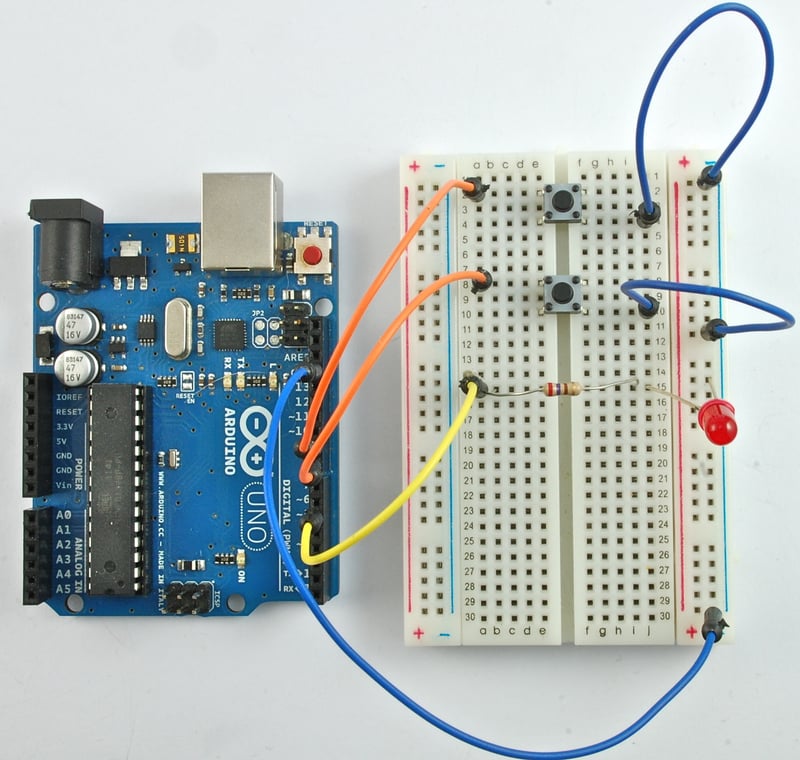
Learn Arduino, Lesson 6. Digital Inputs
pine bramble
is it bad to directly put my LED in the Arduino without a resistor?
long wasp
Yes that is bad
 frosty prairie
Hello, I'm trying to adapt a script written for RGBW Neopixels with MQTT. everything works except effects can't be interrupted. so here's an example effect:
void Rainbow(int speeddelay) {
  unsigned int rgbColour[3];

  // Start off with red.
  rgbColour[0] = 255;
  rgbColour[1] = 0;
  rgbColour[2] = 0;
  while(!shouldAbortEffect()){
    // Choose the colours to increment and decrement.
    for (int decColour = 0; decColour < 3; decColour += 1) {
      int incColour = decColour == 2 ? 0 : decColour + 1;
      if (shouldAbortEffect()) { return; }
      // cross-fade the two colours.
      for(int i = 0; i < 255; i += 1) {
        if (shouldAbortEffect()) { return; }
        rgbColour[decColour] -= 1;
        rgbColour[incColour] += 1;
        setAll(rgbColour[0], rgbColour[1], rgbColour[2], 0);
        delay(speeddelay);
      }
    }
  }
} ```and here is shouldAbortEffect taken straight from the original code.
bool shouldAbortEffect() {
  yield(); // Watchdog timer
  client.loop(); // Update from MQTT
  return transitionAbort;
}
now having never looked into the pubsub library deeply, this code is totally alien to me. any idea's why it doesn't work?
(PS: if I use the fade effect, everything I do while the effect is running is executed after the effect is done.)
pine bramble
can we multithread on an Arduino?
so I modified some code to play happy birthday and I wanted to make the LEDS blinking, but I would have to interrupt the code a lot and I was wondering if there was a way to do both at the same time
inland crag
I think you could DMA the audio and then do the LEDs while it's going but I'm not an expert on this
pine bramble
My circuit suddenly stopped working : \
so my switch isn't working, even after replacing the switch and wires
north stream
That's unhappy.
pine bramble
what could it be?
gleaming fractal
I am trying the "Measuring Battery" sketch on this page: https://learn.adafruit.com/adafruit-feather-328p-atmega328-atmega328p/power-management But I get the error exit status 1 'measuredvbat' does not name a type when I compile it. Any Ideas on this?

Classic ATmega328p tech with the new modern Feathers
north stream
Did you include the float keyword?
north stream
Acts like a missing declaration
gleaming fractal
north stream
Oh, it's a code fragment, it won't work by itself I don't think.
north stream
I wrapped the code with the usual boilerplate
Yeah, it looks like it's missing the Arduino wrapper code
gleaming fractal
Ohhh, okay
Now there's something else it's throwing
OKay, I just created a New blank sketch and pasted those parts into it and it worked
Thanks @north stream
 onyx granite
Hey guys, i have been writing my first real program, one which lights up 4 leds once every half hour or every hour depending on the setting, but for some reason the first led always lights up after 30 seconds, could one of you have a look over my code? thanks, felix.
please @ me if you respond
pine bramble
    if (!blink && elapsedTime >= (timedelay * 4))
        {
        ledState2 = HIGH;
        Serial.println(900000);
        //tone(piezoPin, 2000);
        //  .
        //  .
        }
@onyx granite
pine bramble
When ledState2 = HIGH there, the LED connected at D5 turns on (with the next DigitalWrite to that pin).
 jolly lava
Hi all. Just started learning. Trying to wrap my head around IF statements. What happens when there is an IF statement with another IF statement. I'm really confused to what this part means. Appreciate any help.
    if (digitalRead(hall_pin)==0){
      if (on_state==false){
        on_state = true;
        hall_count+=1.0;
      }
    } else{
      on_state = false;
}```If the hall pin read is 0, it will check if the on stats is true or false, and if it is true, it will set it to false, and if it is false, it sets it to true and adds 1 to the hall count @jolly lava
jolly lava
@onyx granite Thank you so much.
pine bramble
My switch doesn’t work but it did before.
 low hamlet
if you skip the switch and just connect the wires directly to GND or +V? does that work?
I assume you've set up pullup or pulldown in the input
does it work on other inputs?
have you verified the switch is ok? you could for example connect the led/resistor between +V and GND and then insert the switch into the circuit to verify it works indempendent of the arduinio
pine bramble
ill try that
 rough geyser
What wifi library should I be using with the esp32 feather?
I see some different libraries that look like they may be relevant, but I'm not sure what to use
ooooh! ok, after reading a bit I see my mistake, I didn't realize the examples and library needed were included with the board manager install
I now see the "Examples for Adafruit ESP32 Feather -> WiFi -> WifiClient" example
jolly lava
Hello! Just learning how to code multiple sensors. I looked up 3 individual sensor codes (light, moisture and RPM hall sensor), and I combined them. There are probably mistakes everywhere, but generally speaking does the way I combined them work?
Appreciate any help! Thx.
north stream
You probably want to set PinMode() for all 3 inputs.
jolly lava
@north stream thank you so much!
 faint adder
i guess here is a good place to ask,
i recently found this project with arduino ( https://manueldobusch.eu/blog/index.php/2019/03/27/arma-3-desktop-compass/ ) and i was trying to use that as a basis and run it through a seven segment display, but first as a test (because i only have two one digit displays right now)
but when trying that im not sure what part of the code to use or not and i was wondering if i could get some help with it, https://pastebin.com/urtLxE35 this is my mess of code that i put together when testing it, (just a simple servo code combined with Manuel's code)
if i could get any help that would be great or even just tips
 old heart
Can i not put an array into an if statement? if(charsRead == "LINE1") doesn't seem to work
nocturne ivy
nope - you wanted !strcmp maybe?
(array in if is not the problem - == on array is the problem)
old heart
hmm
Well im doing
    if(charsRead[0] == ';') {
      if(charsRead[1] == 'L') {
        if(charsRead[2] == '1') {
          lcd.setCursor(0, 0);
        }
        if(charsRead[2] == '2') {
          lcd.setCursor(0, 1);
        }
      }
    }```
nowjust alot of ifs
Oh yea i can use switch can't i?
nocturne ivy
nope, switch has the same problem - there's no equality check for strings
old heart
hm
nocturne ivy
how many '1', '2' do you have?
old heart
Only 1 and 2
nocturne ivy
if the format is fixed character-by-character, a strcmp/strncmp thing works pretty well, or even your nested ifs. if it's more variable, usually you'll be happier parsing an element at a time, where an element might be "a number" - but you're in the first set. your ifs are fine.
old heart
Ah ok, thank you!
nocturne ivy
if you were any longer, strcmp/stricmp/strncmp - but you're not.
old heart
it doesn't seem to be moving the cursor to line 2?
    if(buffer[0] == ';') {
      Serial.print("Buffer0 = ;");
      if(buffer[1] == 'L') {
        Serial.print("Buffer1 = L");
        if(buffer[2] == '1') {
          lcd.setCursor(0, 0);
          Serial.print("Buffer2 = 1");
        }
        if(buffer[2] == '2') {
          lcd.setCursor(0, 1);
          Serial.print("Buffer2 = 2");
        }
      }
    }```
(`Serial.print`s where so i could tell it was getting to it)I dunno this one - what lcd? are you expecting the cursor to flash in a place, or maybe you print something in the new location and it's in the wrong place?
old heart
I tested putting lcd.setCursor(0, 1); in the beginning of the loop (not in if statements) and it printed on line 2 no problem
lcd is a 16x2
nocturne ivy
since you're not printing in your code, I'm guessing another setCursor is happening between yours and your next print - need more code to spot it.
old heart
#include <LiquidCrystal.h>

LiquidCrystal lcd(2,3,4,5,6,7);

const int tempPin = 0;

char buffer[20];
int charsRead;
int val;

void setup(){
Serial.begin(9600);
lcd.begin(16, 2);
}

void loop(){
  while(Serial.available() > 0){
    charsRead = Serial.readBytesUntil('\n', buffer, sizeof(buffer) - 1);
    buffer[charsRead] = '\0';
    buffer[charsRead - 1] = '\0';

    if(buffer[0] == ';') {
      Serial.print("Buffer0 = ;");
      if(buffer[1] == 'L') {
        Serial.print("Buffer1 = L");
        if(buffer[2] == '1') {

          lcd.setCursor(0, 0);
          Serial.print("Buffer2 = 1");
        }
        if(buffer[2] == '2') {
          lcd.setCursor(0, 1);
          Serial.print("Buffer2 = 2");
        }
      }
    } else {
      lcd.clear();
      delay(1000);
      lcd.print(buffer);
    }
  }
}
my bleeding eyes - where's the close brace for the while
old heart
?
nocturne ivy
I think you wanted to read the whole available buffer, then process it all at once?
old heart
Well my plan is to be able to print on either line
and when typing ";L2" it would switch it to line 2
nocturne ivy
I'm not sure whether it's your problem, but you've got code to process a whole line at a time, and your Serial.read stuff won't necessarily get a whole line.
old heart
Well i get all the Serial prints in the console
nocturne ivy
yeah, if you get the Buffer2 print...hm.
still think something else is moving your cursor under you. you get the clear, the one-second blackness, and then a print in the wrong place?
and you know lcd.clear() doesn't reset the cursor position?
old heart
Yea, it prints on the same line as it was before
Well it should only run the clear when it doesn't detect a ;
nocturne ivy
yeah, but that's the only circumstance it prints anything...
nocturne ivy
fine, but it clears before any print. and if clear resets the cursor...
nocturne ivy
...or add a setCursor after the clear.
old heart
Will do, and yea it was the problem
Would have never thought it was the lcd.clear, thank you!!
nocturne ivy
also be aware your serial reading loop is fragile - I'm guessing it only works because your pc program sends whole lines together. if it was receiving one keypress at a time, it would do something dumb.
but many terminal programs send whole lines at a time, so you're okay only on those.
old heart
Ah ok, I'll keep that in mind
old heart
How would i do something like Line1 = {'T','e','m','p'}; ?
The array is already initialized but i want to change multiple elements at a time
i know you can do
Line1[0] = 'T';
Line1[1] = 'e';
//etc
is there a better way?
low hamlet
@old heart learn about the strcpy() function, https://stackoverflow.com/questions/44488382/about-strcpy-and-memory-on-arduino

Stack Overflow
(I'm warning you I'm very new to the subject of memory allocation)
I'm running this code on my Arduino Uno:
#include <stdlib.h>
#include <Arduino.h>
#include <SoftwareSerial.h>
pine bramble
hi
i request assistance for my virtual yet physical programming device for beginners
.
.
.
i n e e d h e l p
north stream
You'll need to be more specific. A distracting GIF doesn't give any useful information about what you've done so far, what the parameters are, or where you're having a problem.
pine bramble
k
sO
i'm using a beginners arduino kit
DFRobot arduino kit or whatever
and i was using one of their examples called "detecting vibration" or "vibration alarm"
and it already gives me the code for it
but the code isn't working, it doesn't have any errors though
north stream
Do you have a vibration sensor attached?
pine bramble
yes
north stream
What kind of sensor? If it's a passive sensor, you may need to change a line of code.
pine bramble
well idk
north stream
Hmm, how many wires does it have?
north stream
Ah, 2 wires. I'm guessing you hooked one wire to input 3, what did you hook the other wire to?
pine bramble
what do u mean?
north stream
To make a sensor like that work, you have to connect each wire to something.
pine bramble
well i connected it to the white grid board
the uhh "bread" board or something like that
north stream
Yeah, I build a lot of things on solderless breadboards like that. It's a quick way to test things out. However, it matters where things are plugged in.
pine bramble
idk how to say where it's plugged in
north stream
Internally, the holes in the board are connected in parallel rows. So if you have your Arduino plugged into the breadboard (if it's the kind that does that), the holes adjacent to the Arduino pins are connected to that pin.
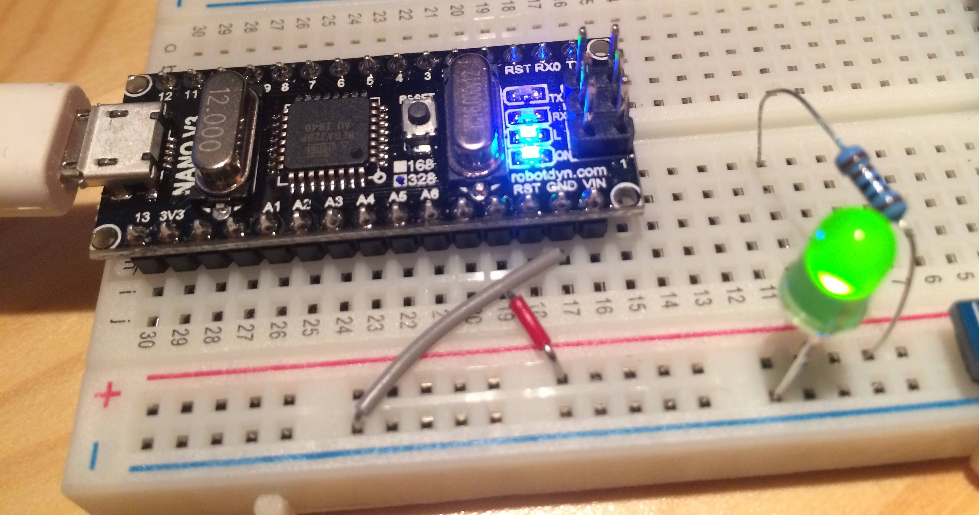 north stream
Ah, okay, looks like you have a shield board on top with a protoboard in it. It also looks like the vibration sensor is connected in a "pull-down resistor" configuration.
pine bramble
is it supposed to have a red light flashing under the breadboard?
because it's 2 layers
because i don't remember from previous projects of having a red light
north stream
The Arduino (the board underneath) has a few LEDs on it. Some of them flash under various circumstances.
Most of them come with a default "blink" sketch that flashes the on-board LED.
pine bramble
ok
north stream
However, if that sketch is running, the LED on top should flash as well, so I'm wondering if I'm guessing correctly.
Perhaps the first thing to do is make sure that the sketches are loading correctly, and that the LED on top is connected the right way around.
(it won't light if it's connected the other way)
pine bramble
one time the examples weren't working so then i made one of the metals touch eachother then it turned on
north stream
Save your vibration sensor test code and try loading the "blink" sketch.
north stream
Mmm, I didn't know it did that. What version are you running?
north stream
Blink didn't work?
pine bramble
oh
i forgot my bad
i tried using vibration alarm agan
brb
blink wont work but it wont give me errors
north stream
Is the board underneath blinking?
north stream
Okay, it may be working, but let's make sure. Change the numbers in the blink sketch and see if the blinking underneath changes speed (bigger numbers should make it blink slower).
north stream
Yeah, that should make it blink 4 times as fast.
pine bramble
kk
ok the green light is blinking faster
but not the LED that is supposed to be working
north stream
Okay, so blink is working, but the LED on top isn't blinking. This tells us some things.
north stream
There are a few possibilities. The most likely is the LED on top is backwards, so try turning it around.
north stream
That could mean a wiring error, a dead LED, a dead resistor, or a problem with the shield.
pine bramble
oof
how do you figure out the one who screws up the whole program because they all look normal to me
north stream
It can be tricky, but you're only looking at 4 parts now.
pine bramble
should i just replace each one
north stream
First eyeball them carefully to make sure you aren't off by a row somewhere.
north stream
Try moving the wire from pin 13 to one of the 5V pins.
north stream
I'm not sure what you're asking.
I pulled up some pictures of the DFrobot prototyping shield, and it looks like it has two long rows of sockets that are green, and 2 short red ones, one short black one, and one short blue one.
pine bramble
the wires are all M/M
north stream
Is the shield plugged into the Arduino correctly? It's possible to have it misaligned so some of the pins in the shield are not plugged into the connectors on the Arduino.
pine bramble
what is the shield
north stream
The Arduino is the bottom board, the shield is the top board.
pine bramble
im trying to push the top board into the bottom board but it wont go
the circular port next to the usb port is blocking t
so its probably the maximum of how far it can go
aw man i gtg
thanks for trying to help me though
north stream
This is what I was referring to: if the pins on the shield aren't lined up with the sockets on the Arduino, the connections will be wrong.
pine bramble
Why do some people use a resistor to use a 4x 7 segment display while others connect it directly?
north stream
I'm guessing you mean LED displays? Technically, the resistor is a good idea to make sure the LEDs do not draw too much power (which could damage your controller or the LED). However, since the controller can only supply about 20mA, the current doesn't get too high and they find some sort of a balance and basically work anyway, however this puts a strain on the controller so I try to avoid doing it.
There's some good details on how this all works here: https://softsolder.com/2012/11/01/arduino-digital-output-drive-vs-direct-connected-leds/

What happens when you jam an LED into an Arduino digital output and turn it on?
pine bramble
Hello! I just started learning about my Elegoo R3. Is it safe to just unplug the USB cable from my computer?
north stream
Yes it is, that device doesn't have any sort of a filesystem that needs to stay in synch, it's just a USB serial connection.
pine bramble
Okay, thanks for the explanation. I just wanted to be safe
Thanks. I find it kinda hard to understand it fully though. Can’t find any tutorials in my native language
north stream
Guessing from your name, your native language might be Arabic?
It does involve some fairly subtle electrical concepts. I'd be glad to try to explain them to you if you're interested, but I'm guessing it would be a lot easier if I spoke your language. The short answer is "the resistors are a good idea".
low hamlet
slightly longer answer is that, LEDs will take all the current they can get. If you dont limit how much you give them with a resistor you risk drawing too much current for both the LED and the driver
pine bramble
My native language is Dutch : p
low hamlet
north stream
Dutch, neat!
pine bramble
im confused on how to set the MCP23017 address. default is A0-A2 grounded equalling 0x20. so im wondering what address having A0 at 5v would give me
0x24 i believe
 solar sail
A0 is the least significant bit, should make the slave address 0x21
stable forge
pine bramble
oh yea, you're right. i saw that diagram and it didn't really make sense how i was supposed to make an address out of it
ty
pine bramble
having no problem addressing my first one at 0x20. this one doesn't seem to want to address at 0x21. after setting up pins every input that i set high still reads low
north stream
Does it show up at some other address on i2cscan?
pine bramble
im on windows, i'll have to lookup how to do that
north stream
It's a sketch you run on the Arduino that simply reports all the I2C addresses that give a response
pine bramble
ah ok, sec
north stream
You might need something like mcp2.begin(0x21)?
pine bramble
tried that didnt think it worked, let me try again
using 0x20 does not work
you have to use 0
so i'm thinking it expects and int between 0-7
none of my inputs on 0x20 seem to work either but the outputs work fine
as far as i know setting them up with mcp.pinMode and setting them high with mcp.digitalWrite is all i need to do
north stream
Ah, yes, it "or"s the supplied address with 0x20. That's a little odd, but okay.
Are you using INPUT_PULLUP?
north stream
There's not. Setting them HIGH looks like it won't work either, looks like you have to call the .pullUp() method instead.
north stream
The "button" example shows the syntax
Heh, I was looking at the source, too. One of the things I like about open source.
pine bramble
ok i think i was just under false pretenses from quickly glancing at button example and thinking pullUp was digitalWrite
because i know i've looked at that a couple times now. 😛
north stream
I might have done the same thing, I tend to skip over stuff thinking "yeah, I've seen that before, I know what to do" and then regretting it later.
pine bramble
figured out my problem the other day with mcp.begin halting was i forgot to hook up common ground between breadboard and arduino lol
north stream
I've done that one too.
pine bramble
well my inputs on 0x20 are working
north stream
Progress!
pine bramble
and some on 0x21 !
think i have some wiring issues now. splitting a 36pin ribbon cable out was a bad idea lol
very easy to get mixed up
got it all straight now. now for the fun part: redoing my whole codebase 😄
north stream
And so it goes...
pine bramble
Can someone help me understand this?
That's a stock 7-segment LED display's schematic. ;)
what you want to understand is what's inside the plastic package (why they managed to provide so many LED segments with so few pins) as you'll note there are far more LED's in that display than there are pins you can solder to, for its package.
The schematic tells you how to utilize that particular display for multiplexing and the like.
The cathodes of each digit of that display are connected together (to save on pins).
It's a four-digit display (with decimal point) and the top half of the schematic is for the common-cathode variant.
The lower half is for the common-anode variant. The two variants have different part numbers, and are sold separately (you won't receive both in a single shipment, unless packed by hand and ordered as such).
pine bramble
I'm trying to understand : P
I managed to turn it on but it doesn't display correctly
You need a series resistance inline with an LED. Usually, about 220 ohms (I think) for segmented displays like those.
The resistors need to be inline with each segment, otherwise the display will be unevenly lit, depending on how many segments are lit at the same time.
(an '8' would appear dimmer than an '1' would appear, if the series resistor was in the common lead instead of inline with the segments .. individually)
pine bramble
I followed a tutorial where there are no resistors being used and currently all the numbers appear to have the same brightness but when I used resistors I had the problem of uneven brightness

In this arduino tutorial I explain how to work with the 4 digit 7 segment led display, and the difference between the four digit display and the one digit di...
The resistors are mainly there in case the controlling program stalls and the design allows 'too many' segments to be lit at the same instant (crisply so).
It's a safety feature. A factory that's producing 10,000 units will design the prototype so as to not require any resistors.
(if the LED is on for a short enough time period, it won't fuse (burn out))
For experiments where you do not (yet) understand everything, the 220 ohm inline resistors can save you loss of parts difficult to obtain (shipping delays more than cost, sometimes, is a reason enough to be cautious).
I usually light segmented displays in groups of four segments (half of a single digit) or sometimes I do the entire digit.
You have to use video blanking for that to work.
Blanking: a short time period in which the entire display (all digits) go dark.
Your mind will mess with it (provide ghosting) if you do not use video blanking.
north stream
Some people depend on the microcontroller to do current limiting, so do without resistors, this trick does appear to work, but it's overloading the microcontroller.
 sour tiger
Are there any examples connecting 2 nrf52 boards to communicate with each other rather than nrf52 to ios or android devices?
 prime anvil
@cosmic comet rather than direct messaging me, I'd suggest asking what you want to ask in here...
 cosmic comet
ARDUINO UNO connected: Il canto del re Arduino se svelia 😂
pine bramble
Hi sorry to bother everyone
Just urgently need some help
I have a 9V battery and the motors I need to power are 6.6V
prime anvil
ok?
pine bramble
One sec I forgot the resistor values
I'm using those three resistors to divide the current into one 6.6volt line
prime anvil
ok
pine bramble
But the circuit did not work
Meaning the motors did not turn on
So what my question is
Is it possibly to turn the 9v line into 6.6v using those resistors?
prime anvil
Did you guess the resistors or calculate them?
Try our easy to use Voltage Divider Calculator. Enter any three known values and press Calculate to solve for the other.
pine bramble
Calculate
But il double check
Yes
200 and 550 ohm
I didnt have a 550 so I'm using one 220 and one 330
prime anvil
so using two resistors in series will create more of a voltage drop than using the equivalent single resistor
pine bramble
Ah
prime anvil
better to find a pair that work for single resistors
you could plug the values you do have into the calculator to figure something out. doesn't have to be too close
eager jewel
You may not have enough current to run the motor. 9v across a 550 ohm resistor is only about 16ma.
north stream
I'm guessing the motor impedance is much less than those resistor values, so they're likely going to not let enough current pass to operate the motor.
prime anvil
better to be using bigger values
north stream
*smaller
prime anvil
doy
eager jewel
A voltage regulator might be a better option for dropping it, though that’s one of many options.
prime anvil
the lazy electronic hobbyist in me would say a 6.6v motor would be fine driven from 9v for short periods...
north stream
You could probably PWM it with a transistor.
prime anvil
pulse width modulation
north stream
Pulse Width Modulate: basically using a microcontroller to turn it on and off rapidly so the average voltage is less than the full supply voltage.
prime anvil
use something like an arduino uno to control a transistor, which in turn switches the motor
north stream
Motors tend to be fairly robust to voltage differences, I wouldn't expect a 6V motor to fry on 50% overvoltage (I've done worse than that and gotten away with it).
pine bramble
So should I try straight up 9 volts?
north stream
Like @prime anvil says, it should be fine for short periods. If the motor starts getting too warm or sparking or something, you might have to look at another approach.
Happily, motors don't self-destruct in the blink of an eye like some electronics (laser diodes in particular).
prime anvil
motors are fairly magic smoke release resistant
pine bramble
Okay, also I connected the motors to the 9volts now in series. For the arduino power do I just connect normally?
Using usb
north stream
An Arduino can't drive a motor directly, it isn't capable of enough current: you'll need some sort of booster like a transistor or relay.
pine bramble
Mmm okay
Let me explain my full situation
So we're making a land and sea rover for our freshmen rapid design project. We previously had normal servo motors which worked perfectly under 5 volts. But we need it to be waterproof so that it can operate at sea. We're using waterproof motors which have 6.6v listed on there
north stream
Oh, are they servo style motors?
pine bramble
Yes
prime anvil
Do the motors just have 2 terminals or many more?
north stream
Ah, that's a different kettle of fish. Those do have electronics in them, and won't enjoy being run on 9V.
pine bramble
Ah
north stream
I was thinking ordinary DC motors, which have nothing in them other than coils, commutators, and magnets.
pine bramble
Ah right sorry for not being specific
prime anvil
If you want an easy solution, presuming you're using an arduino, there are numerous servo shields

The original Adafruit Motorshield kit is one of our most beloved kits, which is why we decided to make something even better. We have upgraded the shield kit to make the bestest, easiest way ...
north stream
You should be able to run those just like your existing servos, on 5V (assuming your power supply has the current capability).
pine bramble
I tried that and it didnt work
prime anvil
What is the servo connecting to
north stream
Can you elaborate on "didn't work"? What happened? Did they move at all? Did the make any sound?
pine bramble
And I would've loved to get that shield but the project is due in a week and they're delivery process at the school is extremely slow
They didnt move at all
And they were cold and no indication of powered
I can try again hold up
north stream
They should work on 4.8 - 6.6V.
But double-check the pinout: some servos use a different arrangement.
prime anvil
Some have red/white/black, some have yellow/red/brown
prime anvil
brown or black = ground (GND, battery negative terminal)
red = servo power (Vservo, battery positive terminal)
orange, yellow, white, or blue = servo control signal line
north stream
How did you power your original servos?
prime anvil
https://cdn-learn.adafruit.com/assets/assets/000/002/310/original/learn_arduino_fritzing_sweep.jpg?1396781578 something like this?

 pine bramble
Yes
I have documentation on my repo one sec

GitHub
Rapid Assembly and Design (RAD) Rover. Contribute to MearazAhmed/Rover development by creating an account on GitHub.
north stream
It could be those hefty 20kg servos draw too much power for the Arduino regulator to supply, and you'll have to come up with another power supply.
pine bramble
There are some errors because I didnt update it
north stream
Can you come up with a higher current 5V supply to run just one servo for testing purposes? A heavy duty USB charger or USB battery pack would do.
prime anvil
AA battery holder?
north stream
4 AA cells would probably suffice for testing, if they're alkaline or NiMH.