#help-with-arduino
1 messages · Page 27 of 1
 odd fjord
FYI -- it looks like the Circuitpython code allows for the faster rates. https://github.com/adafruit/circuitpython/blob/master/ports/nrf/common-hal/busio/SPI.c#L94

GitHub
CircuitPython - a Python implementation for teaching coding with microcontrollers - adafruit/circuitpython
 acoustic nebula
not using any driver, just running SPI with my own code
odd fjord
that simplifies it 😉
acoustic nebula
thanks for pointing out the code, odd that they limit it to 8Mhz when 32Mhz is the chip max
I appreciate that the ESP32 SPI maxes out at 80Mhz and works reliably at that speed 😃
odd fjord
you may want to open an issue in github or post to the forums -- I think the maintainer will be more likely to see it and respond.
acoustic nebula
ok
I'll patch it first and see if the underlying code from Nordic allows faster speeds
acoustic nebula
changed my mind. My ESP32 board happily drives my display at 80Mhz SPI. That will be the target of my project.
 brazen osprey
esp32s are dank af
idk if this fits under arduino but im looking to build a feather based remote controlled robot, and I need help picking out components on the feather side of things
anyone willing to come shopping with me? 🙃
brazen osprey
dank as in pretty cool
 radiant canyon
I don't know if this if the best place for this question but I'm wanting to send serial messages between different boards I currently have 2 Arduino Uno, 2 Micro:bit, 2 Gemma (1 V2 & 1 M0) the next Board I buy will likely be a circuit playground express.or some form of feather I don't know if there is a way to connect these boards to each other I've Looked into I2C and read a fair bit about SPI and UART while I can't find any info about conecting different boards together. It looks to me that UART is likely my best bet.
acoustic nebula
Will your boards be in a one master, multiple slave setup?
if so, I2C would be easiest
brazen osprey
when your question gets skipped 😪
acoustic nebula
sorry Colin, you haven't given any parameters to work from. Cost budget? Speed requirements? Type of wireless you want to use?
How far does the wireless need to reach?
How are you going to power it?
brazen osprey
fair point
I didnt want to just spurt all that out just in case this was the wrong channel for that kind of question
I was thinking RF because it uses relatively low power, but It needs to receive a video feed from the other node while also transmitting simple commands
Didnt know if wifi or bluetooth could do that with decent range, speed, and most importantly, ease of use
Im no beginner to electronics but im pretty new to wireless
acoustic nebula
simple commands for a remote controlled car would probably do fine with an nRF24
video feed would need higher bandwidth like wifi
brazen osprey
would an esp32 be powerful enough to handle the video feed if thats basically its only job
power and cost arent really too big of a factor btw
since I plan to make it modular, cost can just be spread out over time
acoustic nebula
depends on the type of camera - possibly
not enough RAM in the ESP32 to hold an image bigger than 640x480
 wide lark
@brazen osprey the ESP32 would only be good for bit-bucketing the video stream onto another, more powerful device to be decoded. it definitely cannot decode any modern video codec on its own (e.g. H.26X)
brazen osprey
gotcha
as for simple commands, ex. do this or that, would I also use 2.4ghz out of convenience or something else
radiant canyon
My understanding of I2C is that that it is made to connect to sensors & displays is it possible to make the different boards I2C Slaves through software? Can I then send text and number data in both directions?
brazen osprey
btw the video is likely to be far below 720p and ill try to find one that does the compression on its own
wide lark
@brazen osprey devices like the RPI have hardware video decoding blocks, that's really what you want (offloads all the work onto dedicated hardware)
brazen osprey
too big, too much power draw
wide lark
understandable, not sure what your reqs are
brazen osprey
sorry, ill try to give an example
wide lark
@radiant canyon all I2C devices are kind of "slaves", they each have their own address that the main CPU uses to talk to them each individually
brazen osprey
roughly in the size constraint of one of those video drones that (I think) run on 2.4ghz and stream live video to your control device. while id like to have better quality than that, its ok if that isnt feasable
like since my project is feather based, id like to fit the transmitter/reciever chip on a feather sized board
oh wait a minute im an idiot arent I
those video drones usually use your phone to display the video stream
which means theyre probably using the phones processing power to decode the video...
radiant canyon
When I've connected a UNO to a microbit useing a shield with I2C connections the MicroBit only detected the 2 sensors on it's own board the Arduino UNO did also only "see" the 2 I2C sensors on the board
brazen osprey
sorry kiera I think I may have driven off our resident helper by being a complete bafoon
D:
radiant canyon
they may come back later and answer our questions
brazen osprey
hopefully yours
 north stream
I2C is normally for short distances. If your boards are a fair distance apart, you probably want to use a more long-distance protocol. If it's multidrop, you probably want a multidrop protocol like RS-485
wide lark
@brazen osprey sorry had to duck out but yes you're absolutely right, in that situation the phone's video decode hardware would be used (I actually did exactly that at a previous job)
brazen osprey
gotcha
wide lark
@brazen osprey so there you go! as long as you can get the encoded video bitstream to the phone in a timely fashion you'll be good to go
brazen osprey
is it possible that I could use a suped up microcontroller to do both?
(one at each end)
wide lark
@brazen osprey yup definitely... I elided some details about that project I mentioned but that's exactly what we did, a custom SoC in the middle doing some video analytics and then onto the user's phone for decode+display
@brazen osprey (I should note that the intermediary device had to decode the video too of course)
brazen osprey
okay so if I break out the video encoding/transmission/transcoding/receiving to a separate ecosystem, what should I use for simple back and forth communication like "go left" or "perform x command" or "what color is that"
wide lark
@brazen osprey that's up to you! anything that suits your use case... maybe something like a pub/sub pattern?
radiant canyon
@wide lark how can you stop a board from thinking it should be the main controler in software especially the microbit, As far as distance is concerned I'm currently just trying to prove concept with a few simple examples to start with currently anything I "Make" will connect different components via a breadboard or 3
wide lark
@radiant canyon the SoC will just query the I2C bus for any available devices, so they're more cooperative than anything
brazen osprey
mostly just looking for range and speed
wide lark
@brazen osprey oh yeah, if you want range and speed you have only one choice: wifi (or a custom protocol, which is what companies like DJI do)
STAY AWAY FROM BLUETOOTH 😃
brazen osprey
so... RF or?
wide lark
@brazen osprey well "RF" is just a term for the entire band of radio frequency, which includes light and sound. but yeah, if you can I'd suggest wireless over wired, always
@brazen osprey unless you can't just KISS and use 802.11
😉
brazen osprey
well I already decided on wireless, but im asking if I should use something like 2.4ghz wifi or 433 rf or 900 rf
those are my 3 remaining options under the parameters of "feather based"
brazen osprey
oof
wide lark
anyway, I'd stay stick to 2.4GHz 802.11 for ease of implementation
gotta run again, meetings ugh
bbiab
wide lark
anytime, more than happy to! will check back in a bit later
brazen osprey
alrighty Ill be here
radiant canyon
can you please link me to a doc that will point me in the direction I need so I can send info between boards using I2C
brazen osprey
I got nothing, friend. google?
radiant canyon
I've done a lot of searching to find info. Although I prefer Duck Duck Go over Google
acoustic nebula
@radiant canyon https://www.arduino.cc/en/Reference/WireBegin
radiant canyon
Thanks @acoustic nebula
north stream

GitHub
Creates a software I2C/TWI bus on every pins. Contribute to Testato/SoftwareWire development by creating an account on GitHub.
wide lark
@radiant canyon I think sparkfun's I2C tutorial is pretty good too: https://learn.sparkfun.com/tutorials/i2c/all
 glacial light
hi everyone !
( 1st post ever on Adafruit's discord chan 😉 )
I'd like to modify an existing project ( "Slow Dance Time Frame" ), actually getting part of it as a separate, tinier project, but I'm not sure how to "mod" it for what I have in mind ..
Anyone confident enough with Timers & Interrupts ( I'm pretty new to the subject ) ?
More precisely, I need is to replace standard white LEDs by APA102/dotStar, but not sure how if I can get away with just changing the call issued to the leds strip within the ISR to toggle these on/off at the intervals I wish .. ( if I get this correctly, I'd have to check the falling edge as well ? .. )
so, anyone interested in discussing this ? :)
ps: just in case, the "Slow Dance Time Frame" is a quite cool project I invite you to check if not already heard of 😃
radiant canyon
this looks good thanks but while Arduino will work with most boards to turn them into slaves I'm not sure if I'd be better off setting up the microBit as a slave
it is 4am here Brisbane Australia so I need some sleep bye
wide lark
@radiant canyon yikes that's late! sleep is good for you 😃 but yeah, my apologies I'm not all that familiar with the MicroBit, but I'll look into it. sleep well & best of luck with your project!!
north stream
I think you can set up DotStar calls in an ISR as long as you're using SPI hardware to talk to them, otherwise it's likely going to be a little more complicated.
glacial light
@north stream thanks for the hint/answer !
I'm currently using D13 for CLK & D11 for Data to drive the leds, and from what I could read on the subject, 450 leds can take up to 10ms for an update ( I intend to use 16 of those here, so I hope for a ~0.32ms update ). Thing is, contrary to the original code, I am wondering what's the best way to "toggle" those on/off ( I have four ways of doing so in mind, but the latter seems the least complicated if the leds can indeed be called from within an ISR - sine I'm using Timer1, I was thinking about having a wire to D2 or D3 & have an external interrupt attach there to handle the 'CHANGE' edge event )
north stream
You could always do it by having the ISR set a flag and have a loop do the on/off processing when it gets to it. That avoids several possible issues, at the cost of a slight amount of complexity.
glacial light
@north stream yup, understood, also I guess it'd mean declaring 'volatile' stuff as well.
For now, I have in mind either:
- A: doubling the freq & "toggling" within an ISR ( meh .. )
- B: having an additional interrupt for falling edge ( not sure how to yet )
- C: alter the timer/counter's "top" within the ISR ( not sure how effective / error-prone )
- D: one external interrupt on puuled-up pin & "change" handler wired to timer output
- E: your hint
Also, I still have to add comments on the original code to make sure of what it does & continue digging interrupt 😉
north stream
Yeah, you'll end up having a line like ```c
static volatile bool ledFlag;
I think you may be overthinking that frequency doubling, it seems to me you could just have the interrupts happen twice as often instead of trying to catch falling edges, but I freely admit I don't have a good grasp of your actual use case.
glacial light
@north stream sorry for the delayed answer ( phone call :/ .. )
You have in mind any way to have the interrupts happen twice as often ?
The use case is close to this code: https://github.com/cubic-print/timeframe/blob/master/software/TimeFrame_V3_1_full.ino
( I won't be using the magnet part, only the one handling the leds )

GitHub
Get your own time portal on your desk! Contribute to cubic-print/timeframe development by creating an account on GitHub.
north stream
Looks like you'd just change BASE_FREQ to twice as much.
Hmm, maybe not. Looks like that code doesn't use interrupts, just timer-based PWM? It's trickier reading register-level code than the handy wrapper functions.
glacial light
@north stream
Yeah, I know, right ? ( cryptic stuff .. )
Yes, the original code doesn't use interrupts at all since the leds are simple ones driven only on/off using one pin.
For my case, I need an interrupt to be able to map that on/off to APA102 SPI calls.
I was thinking about using TIMSK1 = ( 1<<OCEI1A); to set the output compare enable & then: ISR(TIMER1_COMPA_vect){ /* .. */ } while doubling BASEFREQ
north stream
You're making it harder than it has to be. The APA102 LEDs are "set and forget". They do their own PWM for you, just tell them how bright you want and what color and they take care of the rest.
glacial light
I know that, but thanks anyway ;)
The part I really lack is how to mod the said code just right to reproduce same behavior with the APA102 😃
( although, I had some fun trying to drive those on another platform & reading on the "0xe0+31" brightness setting ;p )
north stream
I'd suggest using the FastLED library. https://github.com/FastLED/FastLED/wiki/Basic-usage

GitHub
The main FastLED library (successor to FastSPI_LED). Please direct questions/requests for advice to the g+ community - http://fastled.io/+ - we'd like to keep issues to just tracking bugs/enha...
glacial light
I already do so ;)
( .. ) FastLED.addLeds<APA102, DATA_PIN, CLOCK_PIN, BGR>(leds, NUM_LEDS);
I "just" have to figure out how to setup the interrupt & within the related ISR my "led state change colors" followed by 'FastLED.show();'
north stream
That should be reasonably straightforward. Alternatively, you can dispense with interrupts and just have code like ```c
#define UPDATERATE 100
static unsigned long next;
void
loop() {
unsigned long curtime;
curtime = millis();

if (curtime > next) {
    // update LED color
    FastLED.show();
    next = curtime + UPDATERATE;
}
}
If you do want to do it using interrupts, there's some good info here https://learn.adafruit.com/multi-tasking-the-arduino-part-2/timers
glacial light
@north stream
thanks for the code, I'll test it 1st thing in the morning / when back ( gotta go 😦 .. )
also thanks for the link, it's actually a pretty good read & I'll have to get a better look at the "Don't call us, we'll call you" whole thing ( could get pretty handy for another project as well 😉 )
I gotta go, but thank you very much for your time, code & patience ;)
-> I'll be back withe a github repo for the said project when good / time to do so
oh, before I foget, that other project I'm talking about ( for which I guess I'll have to opt for Arduino-based stuff for precise timing, just in case anyone 's interested / knows stuff on the travelling salesman problem & related: http://forum.espruino.com/conversations/330092/ )
+
north stream
Not necessarily Arduino, but for precise timing you'll want some sort of low-level control. And, yes, hardware SPI is your friend.
 harsh wind
does anybody know about programming arduino sketches in VSCode? I keep getting an "include error" and I'm not sure if there's a specific setting i need to change in vscode to direct the sketch to the correct path or if there's a simple thing I'm missing.
 nimble terrace
maybe add #include <Arduino.h> at start
i need that sometimes on VSCode + plateformio using .cpp
 odd bloom
i found this code on the arduino project library for a joystick to control a stepper motor. but my problem is that when the joys stick isn't being pushed the stepper motor still turns
int s1 = 5;
int s2 = 6;
int s3 = 7;
int s4 = 8;
int x;
void setup() {
pinMode(s1, OUTPUT);
pinMode(s2, OUTPUT);
pinMode(s3, OUTPUT);
pinMode(s4, OUTPUT);
pinMode(A0, INPUT);
}
void loop() {
x = analogRead(A0);
if(x<500)
{
digitalWrite(s1, HIGH);
digitalWrite(s2, LOW);
digitalWrite(s3, LOW);
digitalWrite(s4, LOW);
delay(5);
digitalWrite(s1, LOW);
digitalWrite(s2, HIGH);
digitalWrite(s3, LOW);
digitalWrite(s4, LOW);
delay(5);
digitalWrite(s1, LOW);
digitalWrite(s2, LOW);
digitalWrite(s3, HIGH);
digitalWrite(s4, LOW);
delay(5);
digitalWrite(s1, LOW);
digitalWrite(s2, LOW);
digitalWrite(s3, LOW);
digitalWrite(s4, HIGH);
delay(5);
}
else if(x>550)
{
digitalWrite(s1, LOW);
digitalWrite(s2, LOW);
digitalWrite(s3, LOW);
digitalWrite(s4, HIGH);
delay(5);
digitalWrite(s1, LOW);
digitalWrite(s2, LOW);
digitalWrite(s3, HIGH);
digitalWrite(s4, LOW);
delay(5);
digitalWrite(s1, LOW);
digitalWrite(s2, HIGH);
digitalWrite(s3, LOW);
digitalWrite(s4, LOW);
delay(5);
digitalWrite(s1, HIGH);
digitalWrite(s2, LOW);
digitalWrite(s3, LOW);
digitalWrite(s4, LOW);
delay(5);
}
else if(x > 500 && x < 550)
{
digitalWrite(s1, LOW);
digitalWrite(s2, LOW);
digitalWrite(s3, LOW);
digitalWrite(s4, LOW);
}
}
how should i fix this?
north stream
You need to find out what the joystick reads when it's centered or idle, and change the 500 and 550 numbers to be above and below that.
Note they may be different for X and Y.
odd bloom
how would i find the value to the centered position?
odd bloom
hello?
north stream
Was out having dinner. Just write a loop to read and print the X and Y values and view them in the serial monitor
odd bloom
o sorry
harsh wind
Hey @north stream i keep getting an 'include error' when writing this code and its something to do with some sort of setting in VSCode or the path they're located in. It worked in the arduino IDE with an Arduino nano but now Im trying to do it with a 'Particle Boron' with VSCode and the compiler says it can't find the included files. Do you maybe know what might be wrong?
odd bloom
how would i add the loop read?
harsh wind
@nimble terrace I tried that, it didn't work. Thanks for the tip tho!
north stream
I have no idea what VSCode is
odd bloom
like what code would i put in the program
harsh wind
Microsoft Virtual Studio
north stream
I've never used it.
north stream
@odd bloom Something like ```c
void
setup()
{
Serial.begin(9600);
pinMode(A0, INPUT);
}
void
loop()
{
int x;
x = analogRead(A0);
Serial.println(x);
sleep(1);
}```
harsh wind
that's okay i was just wondering since i see you answering lots of peoples questions. Thanks anyways!
north stream
I generally only speak up if I think I have something useful to offer. And I freely admit I don't know everything!
I think the last time I saw Visual Studio was in 1999, and it was pretty awful then.
odd bloom
thanks mad
north stream
I was writing a device driver for Windows NT for a custom crypto board I had designed. It was easily 20 times harder than writing the Solaris driver was.
harsh wind
Yea, its still pretty awful now xD
at least when you're an inexperienced programmer like me with ideas and projects that are higher tier than my own programming skills
its not really the code its just how the IDE works and all the stupid manual path settings and stuff
north stream
I got very spoiled using things like SparcWorks and CodeWarrior.
north stream
The answer is out there, the trick is to find it!
odd bloom
so my full throttle left give the number 0, and my full throttle right gave 1023, my center is 497, what should i do
i cant seem to figure out which numbers to use
north stream
The original code had 3 ranges: <500, 500-550, and >550. Since your center is 497, it would be in the lower range when it should have been in the middle (neutral) range. So I'd suggest changing the ranges to <475, 475-525, and >525.
In other words, change the 500s in your original code to 475s, and the 550s to 525s.
The idea is to put your center value (497) into the middle of the middle range. You could do it mathematically (and in fact, if I were writing it, that's how I'd do it), but just changing the numbers to match your readings will work, and is simpler.
It looks like the original code was written assuming the center value was about 525.
 pine bramble
how is it possible to send packages of more than 20 Bytes from an Adafruit nRF52840 feather device to a Smartphone? I've seen that in the device example code the bandwidth_max is set. when i try to connect from a android phone and try to set up the data size length (mtu) up to 512 it first responds with 247 byte but shortly after (about 2 sec) it gives an error message and setting it back to 20 bytes.
odd bloom
Thanks @north stream that really helped
 torn frigate
https://cdn.discordapp.com/attachments/476228839740014612/545631946181443604/SkZcAP9.png
hey, do you think this will work well?
4 soil humidity sensors FC-28
with ESP8266 Wemos D1 R2
please let me know if I'm missing anything, is my first project 😔
 north stream
As we discussed before, that MCU board only has one analog input, so you'd need some way (multiplexer or outboard ADC) to read more than one analog sensor at a time.
torn frigate
thanks
 sharp heart
I bought the 2.8'' TFT Shield and want to connect it to an ESP32.
I'm following this guide: https://learn.adafruit.com/adafruit-2-8-tft-touch-shield-v2/connecting
I've connected the pins from section "TFT Screen Pins" and configured ESP32 to use SPI.
While it doesn't crash, nothing is showing on screen.
Then, further down the page, in section "Using with a Mega/Leonardo" it says that if I want to use ICSP I need to cut some jumpers and solder others.
Looking at the picture and then my board, it seems that it is already configured to use ICSP. Where the picture shows the 3 digital pins connected, mines are not.
So, does this mean I need to do the opposite if I want to use SPI?

Spice up your Arduino project with a beautiful large touchscreen display shield with built in microSD card connection.
north stream
Basically, there are two ways to get the SPI signal into the board, via the digital I/O pins or the ICSP connector. How you set the jumpers determines which input to use. In other words, you can leave the jumpers alone and connect the TFT to the ESP32 via the ICSP connector, or adjust the jumpers and connect the TFT via the GPIO pins.
acoustic nebula
Not sure about that board, but the 2.2" PiTFT has the 5V line of the Pi connected to the LCD backlight
To make it work on the ESP32, I tied the 5V line to the 3V input and it works fine
sharp heart
I just adjusted the jumpers and connected it with GPIO pins. Still not working.
Then again, I'm using the ESP32 Lyrat, so maybe that's the issue?
For power, I actually have an external 5V input that is completely separate from the rest and I just connect it to the TFT
 sharp heart
@acoustic nebula Do you only have 1 power pin, or are there more? So far I only connected the backlight. Not sure if there's more.
acoustic nebula
I connected the 3.3v line from the ESP32 to both the 3.3v and 5v lines of the Pi header
then common ground, SCLK, MOSI, D/C and RESET
and CS
you can get away with tying CS low also
sharp heart
hmm... ok, I might be missing a power pin then. I only connected a 5v one.
acoustic nebula
check the schematic of the board to make sure you're powering it correctly
sharp heart
The Lyrat doesn't seem to have power pins, so I'm using an external one. Will that be an issue??
acoustic nebula
what's a Lyrat?
sharp heart
actually, I think I see a 3v one.
It's the ESP32 Lyrat dev board for music: https://www.espressif.com/en/products/hardware/esp32-lyrat
 gentle viper
Is there a way in Arduino IDE to test using the computers internet instead of accessing the wifi of the chip?
acoustic nebula
I can see the big linear regulator on the board
it regulates the 5v coming in from the usb to 3.3v to run the chip
you can tap into that same 3.3v to power the LCD
computers internet?
sharp heart
@gentle viper http://playground.arduino.cc/Code/SerialIP
gentle viper
@sharp heart is that assuming the board is connected?
I just need to test Console feedback with out a device.
sharp heart
I believe that's setting up a service that runs on your PC that the connected Arduino communicates via USB.
gentle viper
Yea, im just testing an api and want to make sure it's returning a value before putting it on a board.
nimble terrace
Hello, How can I stream only N lines of a file ?
north stream
You could either read it a line at a time and stop when you get to N lines, or (the no-buffer solution) read a character at a time and count newline characters, stopping when you get to N.
nimble terrace
I manage to use Serial.write(file.read()); in a while with a break condition
but instead of Serial.write() id like to put the content in a variable
sharp heart
@acoustic nebula Looking at the schematic here, it looks like the SPI pins run on 5V? Am I reading that right? If so, will that not work for ESP32?
https://cdn-learn.adafruit.com/assets/assets/000/027/040/original/adafruit_products_cap_touch28_tft.png?1438860497

Top left of the arduino are the SPI pins. It says "MOSI_5V", etc.
north stream
Those go into a 4050 chip, which will accept either 5V or 3V signals and provide 3V outputs. It's included so the board will operate correctly with either type of signals.
sharp heart
Cool. So, from what I can see, there's only 1 pin used for VCC, and that's the 5V one.
The 3V seems to be left alone
And from I can tell, that's just the backlight
north stream
Yeah, the 5V is used for the backlight and I2C level shifters, and an on-board regulator produces the 3.3V supply from that.
sharp heart
OK. I connected it to the 3V and indeed backlight works fine. So something else is not working..
north stream
I'd connect the 5V input to a 5V supply.
sharp heart
It doesn't seem to have a difference.
Code output seems that everything is being sent to the screen. The screen just isn't doing anything. I'll check my connections again.
north stream
What do you get on the serial console?
sharp heart
I'm using this library
and just running the demo
It's just printing out the demo output
It get stuck in the "Send color buffer", but eventually continues to the next test
north stream
Looks like it's talking to the display, so your connections are likely correct.
That SPI speed looks unrealistically fast, you might try setting it to something slower.
sharp heart
OK. I'm gonna try to find where that is.
nimble terrace
why we need Serial.write(file.read()); ? and how to get something like content += file.read() where content is a String or maybe better a file ?
sharp heart
@north stream Found where the speed is set. I'm assuming you are talking about the "SPI: Changed speed to 26666666". What would be a good speed?
north stream
I'm not sure. Maybe use something like ```c
tft.begin(1000000);
FWIW, the library has that speed as the default for this chip https://github.com/loboris/ESP32_TFT_library/blob/aa21772f54a71887ec08b2e8bbaef9e304009891/components/tft/tftspi.h#L48

GitHub
Full featured TFT library for ESP32 with demo application - loboris/ESP32_TFT_library
north stream
Oho, you're using a different library!
That library has several things you need to set for it to work right. Which controller did you set it to?
sharp heart
ILI9341
Yes, I'm not using the adafruit one.
Mainly because that depends on using esp-idf with the Arduino as a component. I wanted to use a "pure" esp32 library
I'm not using Arduino at all.
I'm building the project with VS Code and esp-idf
 mild elk
Is it possible to make an arduino execute a some code in a loop for specified amount of time and then move on with the code?
north stream
Yeah. Something like ```c
unsigned long stoptime;
stoptime = millis() + TIMETORUN;
while (millis() < stoptime) {
// do stuff
}
// now do other stuff
You can get fancier with it, if you want to keep calling loop() while stuff is running, but that's the gist of it
mild elk
TIMETORUN is in milliseconds?
 honest nimbus
Yep
mild elk
Ok thanks
sharp heart
What's a good alternative way to connect to a breakout board so it can stay flat on a surface?
For example, I'd like to connect the holes in this display vertically: https://cdn-shop.adafruit.com/970x728/2090-00.jpg

Nevermind, I found Right Angled headers.
 rigid rain
I'm using the arduino pro mini and want to use the rx and tx pins after flashing without disconnecting the programmer. Does anyone know a solution to this problem? I want to use the rx and tx pin to use a bluetooth module.
north stream
I think you can do so: the RX and TX pins are tied to the USB-serial interface by decoupling resistors, so you should be able to use them to operate a Bluetooth module when you're not programming it. The caveat is that you won't be able to program the Pro Mini if the Bluetooth module is driving its TX line.
rigid rain
Okii. WIll try. I had some issues while flashing. The programming said not responding, and after flashing the bluetooth module stopt working if the tx and rx of the programmer where connected
rigid rain
It doesnt work. connect both devices at once. I'm probably gonna make some hardware solution to disconnect the serial to the bluetooth device when flashing
mild elk
Program it through icsp
north stream
Yeah, the usual approach is a couple of pins with a removeable jumper on them.
rigid rain
@mild elk Mmm never heard about that. I will take a look at it
mild elk
If You have another arduino, you can turn it into a programmer
And program the chip directly without rx and tx or even without bootloader
But I always burn bootloader first to set the fuses
rigid rain
I've got multiple arduinos lying around so that should be a problem! The only problem is that I don't use the arduino IDE so I don't know how to do this without that IDE
rigid rain
I want to write plain c++ instead of arduinos implementation of c++
I prefer to do it all on my own 😛
north stream
Yeah, you can program it directly using Atmel Studio or whatever.
mild elk
Arduino IDE makes it a lot easier if You want to quickly test something. Arduino c++ isnt that much different. And You can use ArduinoISP
I'd recommend You to get it anyway
@rigid rain
mild elk
I can guide You
rigid rain
Sounds nice!
rigid rain
yes sir!
mild elk
So first get the arduino ide
rigid rain
Got it already. Arduino is connected aswell
rigid rain
Got it
mild elk
Yeah
rigid rain
Okee did that too
mild elk
Now go to file -> examples -> ArduinoISP
rigid rain
Done
mild elk
Upload the sketch
rigid rain
Done uploadign
mild elk
Ok now unplug uno from Your computer
rigid rain
Ok
mild elk
Connect 5v pin on pro mini to 5v on uno
Gnd to gnd
13 to 13
12 to 12
11 to 11
And pin 10 of uno to reset of pro mini
mild elk
Ok
rigid rain
Gimme few sec. Checking if none of the cables are broken 😛
mild elk
Ok np
rigid rain
Connected everything
mild elk
Just keep in mind that when You program it like this You will not be able to program it through tx and rx. You would need to re-burn the bootloader to do that, because programming through icsp erases the bootloader. The good thing is that You now have all the space on the chip available and Your code starts executing right away
mild elk
Ok now get Yourself a 10uF capacitor
rigid rain
Aint got any capacitors at home. All at school...
mild elk
Ok
Look for 10uF electrolytic
I have to go to sleep in like 15 minutes because its late so if You didnt manage to do it in 15 minutes I'll have to just leave rest of the instructions here
mild elk
Ok so basiclly You now have to go to tools -> board and select pro mini
Now go to tools -> programmer and select "Arduino as ISP"
Then get the 10uF capacitor and plug its positive lead to the reset pin of the programmer and its negative lead to gnd
Open Your code in arduino IDE
Connect programmer back to the computer
Now hold shift and when You hover Your mouse over the upload button it should say "upload using programmer"
Click it and now all the leds on the programmer arduino will go crazy
Just wait until they stop flashing and Arduino IDE should say "done uploading"
Now You can unplug the programmer from Your computer
And then pro mini from the programmer
And thats it
rigid rain
Okee
Thank you soo much
Cant thank you enough!
Tommorow I'm gonna get the caps and try it!
mild elk
If You face any problems just ping me
mild elk
Thanks!
rigid rain
You deserved it 😛
 wintry berry
is there a way to control 2 pwm pins with 1 analog input? in a way that 0-500 = control the first pwm pin (0 is max 500 is min)
and 524 - 1023 control the second pwm pin (524 is min and 1023 is max)
if the analog input is 500-524 both pwm pins need to be off
north stream
Yeah, a little if-else logic ```c
in = analogRead(INPUT_PIN);
if (in < 500) {
analogWrite(PWM1_PIN, map(in, 0, 500, 255, 0));
analogWrite(PWM2_PIN, 0);
return;
}
if (in < 524) {
analogWrite(PWM1_PIN, 0);
analogWrite(PWM2_PIN, 0);
return;
}
analogWrite(PWM1_PIN, 0);
analogWrite(PWM2_PIN, map(in, 524, 1023, 0, 255));
Hey, is it possible to hack a common sensor to read his values on arduino, something like : https://images-na.ssl-images-amazon.com/images/I/41RFUR87s3L._SL1024_.jpg

 wild hawk
Hiiiiiiiiiiiiii all! Fast question: I'm building a crawling robot that is actuated with 4 DC motors controlled using PID on an arduino MICRO. It functions well and I am ready to make it remote control. What is the best choice: RF, BT, IR, WIFI, or anything else? And why? Thanks!
north stream
Most sensors can be hacked, but the effort required varies a great deal depending on the sensor design.
Heh, "best" depends on what parameters are important to you. For example, IR is fairly cheap, simple, and fast, but only works if the sensors can see each other, and can be interfered with fairly easily.
Wired remote is super cheap, simple, fast, and very secure and resistant to interference, and can deliver power as well, but you're tethered by a wire you're dragging around.
Bluetooth is more complex, expensive, and slow, but you can use a phone as a remote, it's not sensitive to direction, and is resistant to interference and spoofing.
nimble terrace
nice bot !!
As there is a screen on the tester, I wonder if it is easy to get the signal at this point. This is from an educationnal point of view, and because I already have some, investing in a real sensor is another topic.
nimble terrace
some guys did good work on that topic https://forum.arduino.cc/index.php?topic=180333.0
ph-logger from cheap ph meter from DX
nimble terrace
but yeah it is way over complicated
north stream
The signals used to drive an LCD display like that are somewhat ornate, and decoding data from them can be a chore.
nimble terrace
I have a dilema : since a week I'm discovering arduino and C++ and managed to use webserver, sd, sensors. And now I wonder if I should develop my C++ knowledge or go to micropython world ?
I'm already familiar to python, and the micropython workflow look way more suitable to create application with a lot of code.
mild elk
Stay with c++
nimble terrace
ok ! but why ? micropython is not mature enough yet ?
north stream
MicroPython takes care of a lot of the details for you, but doesn't support everything and can offer lower performance than a low-level language like C++. The low-level language is a lot more finicky, but lets you do anything.
nimble terrace
ok, thx for the insight. I will stay c++. Having enjoyable use cases is pretty important to learn software, Arduino is perfect here.
Any good coding tutorials recommended ?
 placid snow
I don't get it anymore. I have try'd changing a lot of code and deleting and adding code, but I still get this weird error. When I run and compile my code for esp32 and open the serial monitor it keeps printing:
Broadcast
oadcast
adcast
dcast
cast
Code: https://pastebin.com/Ui6t5JxR
Can somebody help?
 nimble terrace
did you try to lower the serial speed ?
placid snow
No, didn't try that, moment
nimble terrace
Im on esp32 too and stuck at 9600 idk why
placid snow
"broadcast" is part of my code
nimble terrace
yes le serial output looks stuck at this point
placid snow
Still getting the same messages on 9600
north stream
I'm not sure why the compiler even allowed this line ```c
udp.onPacket([](AsyncUDPPacket packet) {
this is lambda function
placid snow
Whats wrong with that line?
Yeah okay thats not 100% normal
Wow deleted the udp on packet part and now its printing my wifi code
arg
nimble terrace
im new to arduino, cant help much, but yeah try to isolate the problem
placid snow
eyy when doing String(int(colCtr)) + " " + String(int(rowValue[0])) the problem stops
still its a weird problem
nimble terrace
yesterday i had a weird problem with a char variable, i dirty fixed it by hardcoding it twice in the code
north stream
C++ type promotion is ... odd.
north stream
By going to FORTH?
nimble terrace
luckly it is hard to go back :0
 vague tapir
Good afternoon. I'm trying to use an itsy-bitsy m4 with arduino. I am using version 1.8.7 arduino IDE, set additional board manager url to https://adafruit.github.io/arduino-board-index/package_adafruit_index.json, installed the drivers posted on the itsybitsy guide (https://learn.adafruit.com/introducing-adafruit-itsybitsy-m4/setup), added the samd support under board manager, rebooted the ide and the device, and keep receiving this message:
Arduino: 1.8.7 (Windows 10), Board: "Adafruit ItsyBitsy M4 (SAMD51), Enabled"
In file included from C:\Users\usmcr_000\AppData\Local\Arduino15\packages\arduino\tools\CMSIS-Atmel\1.2.0/CMSIS/Device/ATMEL/samd51/include/samd51.h:40:0,
             from C:\Users\usmcr_000\AppData\Local\Arduino15\packages\arduino\tools\CMSIS-Atmel\1.2.0/CMSIS/Device/ATMEL/samd.h:141,

             from C:\Users\usmcr_000\AppData\Local\Arduino15\packages\arduino\tools\CMSIS-Atmel\1.2.0/CMSIS/Device/ATMEL/sam.h:540,

             from C:\Users\usmcr_000\AppData\Local\Arduino15\packages\adafruit\hardware\samd\1.2.9\cores\arduino/Arduino.h:48,

             from sketch\ItsyBitsyBlink.ino.cpp:1:
C:\Users\usmcr_000\AppData\Local\Arduino15\packages\arduino\tools\CMSIS-Atmel\1.2.0/CMSIS/Device/ATMEL/samd51/include/samd51g19a.h:521:22: fatal error: core_cm4.h: No such file or directory
#include <core_cm4.h>
^
compilation terminated.
exit status 1
Error compiling for board Adafruit ItsyBitsy M4 (SAMD51).
I see the line saying up to "samd51g19a.h:521:22: fatal error: core_cm4.h: No such file or directory" is missing, I have the samd51ga.h, is there something i failed to download or missed a step?
 eager jewel
@vague tapir, did you install the Arduino SAMD boards as well?
vague tapir
@eager jewel yes, I double checked to make sure, I added all the Arduino SAMD boards. They are all installed.
north stream
I think you may also need the Arduino SAM boards
eager jewel
Oh, good point @north stream. Also, I think the latest IDE is 1.8.8.
vague tapir
@north stream I have that one as well. The only one that I don't have under "SAM" in board manager installed is the industriduino manager.
@eager jewel Thank you, I'll look at updating.
north stream
As far as I can tell looking at the package index, the SAMD package had a dependency on arduino CMSIS, which in turn should contain the missing file. Unsure why it's not there.
vague tapir
I looked at the samd51g19a.h file and the core_cm4.h is in there, but from the error above, what is the significance of the additional :521:22
eager jewel
I think that means line 521, character 22.
vague tapir
oh ok, thank you @eager jewel
eager jewel
yw
vague tapir
Looks like I had to remove the packages, twice for some reason, before they'd update. Seems to work now. Thank you @eager jewel and @north stream for the help.
eager jewel
You're welcome. Glad to hear it's working for you now.
 frigid surge
Yo I am hosting a small website off my arduino to control my hue lights
But when I try to add a google analytics tracking code to it
it doesn't work cause the arduino ide seems to add random C comments in the code
north stream
Looks like the C preprocessor is adding comments for some reason.
north stream
I don't know, it depends on how this is being generated. Those comments are normally for the use of a debugger and are emitted by the compiler when it processes source code. Perhaps you're putting your web site data in your source code?
frigid surge
Yes
It's just in a variable
sec let me remove all the personal things
And post the source code here
I'm just running normal Arduino IDE no special stuff
north stream
I think the answer is going to be to store the data another way.
frigid surge
Well it only adds it for the analytics tag
all the other html and scripts are fine
Even if I move it elesewhere
 north stream
That's odd. You may have to declare your string literal differently.
Maybe the quotes per line format?
const char MAIN_page[] PROGMEM =
"<!DOCTYPE html>"
"<html lang=\"en\">";
Alternatively, you could store the string separately, or escape the newlines.
north stream
In that case, I'd probably just encode the whole thing and store it like that:
frigid surge
I could probably make it a single line
north stream
const char MAIN_page[] PROGMEM = {
0x3c, 0x21, 0x44, 0x4f, 0x43, 0x54, 0x59, 0x50,
Or store the HTML/JS in a separate file and slurp it into the flash image at build time (I'll admit I don't know how to do that, but it would be elegant).
frigid surge
lol
const char MAIN_page[] PROGMEM =
"<!DOCTYPE html>"
"<html lang=\"en\">";
Doing this^ but minifying the html to a single line worked
neat
north stream
Cool!
frigid surge
I'll look into separate files now cause I agree that'd be much better
Still very new to this whole thing I just found my esp8266 thing a week ago and started trying to make it work
north stream
The last time I had to do something like that, I ended up writing a separate program to convert it all into hex and then hid it in a header file that I included in my .ino file.
frigid surge
Hmm
north stream
I would expect the C preprocessor to have a #pragma directive to turn off the line numbering, but I don't see anything like that.
 sand lichen
@wintry berry Regarding your question about controlling two pwm pins, there's a way to do it without if statements: ```arduino
in = analogRead(INPUT_PIN);
analogWrite(PWM_P1, (constrain(map(in, 500, 0, 0, 255), 0, 255)));
analogWrite(PWM_P2, (constrain(map(in, 524, 1023, 0, 255), 0, 255)));
The constrain function holds the PWM duty_cycle at the minimum of constrain's limiting range when the result of the map function goes beyond its specified output range.
In CircuitPython, the map_range helper in simpleio combines the functionality of the Arduino map and constrain functions as shown above.
eager jewel
Oh, good tip @sand lichen . I didn't know about that one.
sand lichen
It really simplified working with timed LED animation.
eager jewel
Yeah, I've used map in arduino, but I didn't know about the CP one.
 placid radish
i need help with the L298N Dual Motor Controller Module. I hooked it up to my arduino uno and a 12v 2A power suplly but as soon as i plug a small motor into the motor output ports the voltage drops from around 5v to .01v
radiant canyon
A few days ago I asked about connecting My Arduino UNO to a microbit using I2C to send serial messages back and forth as they are both Master devices I was looking at ways to turn one of them into a slave device. But maybe there is a better way would I be able to send Data to something like https://www.adafruit.com/product/1895 and read it with the other?

FRAM, or Ferroelectric Ram, is the coolest new data storage method that all the fashion magazines are talking about. Oh wait, no that's quilted handbags. But FRAM is pretty damn cool ...
north stream
@placid radish Sounds like a hookup issue (since it doesn't happen without a motor hooked up, I doubt it's shoot-through). The controlling CPU, the L298N, and both power supplies need to have their grounds all connected together. Otherwise you'll have a floating situation.
@radiant canyon I don't think the FRAM is dual port, so you'd have to worry about collisions. It's probably easier to use serial communication.
placid radish
@north stream yah thank you i didnt have the arduino hooked up to ground
 radiant valley
does anyone know where i can find the library for the DS1307 Real Time Clock
odd fjord
@radiant valley It is called RTClib by Adafruit in the library manager -- https://github.com/adafruit/RTClib
GitHub
A fork of Jeelab's fantastic RTC library. Contribute to adafruit/RTClib development by creating an account on GitHub.
radiant valley
has anyone used one of these clock modules before
north stream
I've used the related DS3231
odd fjord
there is a guide here that may help https://learn.adafruit.com/ds1307-real-time-clock-breakout-board-kit/understanding-the-code

Real time clock mini-breakout board
radiant valley
thats what ive been looking at
north stream
The time setting code there simply uses the time when the code is built. I wrote another version that gets the time from the host computer.
Is it not working for you?
north stream
I think it gives back whether the clock is currently running, the current date and time, then the number of days since 2000 and the current time plus a week.
radiant valley
21165 85 165 165 25 165 165 PM T=-9999.00 O- A1! A2!
Alarm 1: 15 DoW 25 85 85 27936enabled
Alarm 2: 15 DoW 25 85 28781enabled148801111111
ths is what is being printed
north stream
Hmm, that looks like different code. It seems to be giving an invalid time, and pointing out that both alarms are enabled but not set, and giving the Unix time.
Might be worth running the version to set the time.
north stream
As long as it's powered, I'm guessing it will keep time, but it will forget everything if the power supply goes away and it doesn't have a backup cell installed.
radiant valley
should i just do that to reset it
north stream
The numbers it's giving look like the time isn't set, so I'd just set the time.
radiant valley
Clock.setClockMode(false); // set to 24h
//setClockMode(true); // set to 12h
    Clock.setYear(Year);
    Clock.setMonth(Month);
    Clock.setDate(Date);
    Clock.setDoW(DoW);
    Clock.setHour(Hour);
    Clock.setMinute(Minute);
    Clock.setSecond(Second);

    // Test of alarm functions
    // set A1 to one minute past the time we just set the clock
    // on current day of week.
    Clock.setA1Time(DoW, Hour, Minute+1, Second, 0x0, true,
        false, false);
    // set A2 to two minutes past, on current day of month.
    Clock.setA2Time(Date, Hour, Minute+2, 0x0, false, false,
        false);
so in the clock set
add information
?
north stream
I don't remember that in the tutorial. I was thinking of this bit ```c
if (! rtc.initialized()) {
Serial.println("RTC is NOT running!");
// following line sets the RTC to the date & time this sketch was compiled
rtc.adjust(DateTime(F(DATE), F(TIME)));
@north stream do you still have your code
im trying to get it to work for a mega
and it continues to say Error compiling for board Arduino/Genuino Mega or Mega 2560.
north stream
radiant valley
there is a error uploading to the mega
any ideas?
// SDA A4 SCL A5 for Uno
i think its ports
north stream
Error compiling or error uploading? I doubt it's the ports at that point.
radiant valley
Using library Wire at version 1.0 in folder: C:\Program Files (x86)\Arduino\hardware\arduino\avr\libraries\Wire
exit status 1
Error compiling for board Arduino/Genuino Mega or Mega 2560.
Invalid library found in C:\Users\Lorenso\Documents\Arduino\libraries\Adafruit_TCS34725-master: C:\Users\Lorenso\Documents\Arduino\libraries\Adafruit_TCS34725-master
Invalid library found in C:\Users\Lorenso\Documents\Arduino\libraries\Adafruit_TCS34725-master: C:\Users\Lorenso\Documents\Arduino\libraries\Adafruit_TCS34725-master
is there a way to update the libaries
north stream
Yeah, go to the library manager. It looks like you may have some stuff from an older installation (before there was a library manager) that may be confusing it.
radiant valley
??
north stream
You can get to the library manager from Sketch -> Include Library -> Manage Libraries
radiant valley
im updating all of my libaries now
@north stream where can i find #include <LiquidCrystal_I2C.h>
i cant fine it in the libary manager
north stream
I thought the #include for LiquidCrystal was just LiquidCrystal.h
Ah, there's a separate library for that: https://github.com/fdebrabander/Arduino-LiquidCrystal-I2C-library
radiant valley
exit status 1
expected primary-expression before 'static'
north stream
north stream
Usually those "expected <something> before <something>" type errors mean a syntax error previously. You need to look at the lines leading up to where the error was detected.
radiant valley
Multiple libraries were found for "Firmata.h"
Used: C:\Users\Lorenso\Documents\Arduino\libraries\Firmata
Not used: C:\Program Files (x86)\Arduino\libraries\Firmata
try2:14: error: 'POSITIVE' was not declared in this scope
static LiquidCrystal_I2C lcd(ADDR_LCD, 2, 1, 0, 4, 5, 6, 7, 3, POSITIVE); // Set the LCD I2C address
north stream
I don't know which library I used there (weirdly, it doesn't seem to be installed). Just remove all the LCD stuff, you don't need it to set the clock.
north stream
It was never intended as finished code, just something I was playing with
radiant valley
what is the firmata
static void
Wire.beginTransmission(ADDR_RTC);
Wire.write(0);
Wire.write(getdigits(msg + 12)); // second
Wire.write(getdigits(msg + 10)); // minute
Wire.write(getdigits(msg + 8)); // hour
Wire.write(getdigits(msg + 6)); // day of week
Wire.write(getdigits(msg + 4)); // day of month
Wire.write(getdigits(msg + 2)); // month
Wire.write(getdigits(msg + 0)); // year (2 digit)
Wire.write(0);
Wire.endTransmission();
}
expected initializer before '.' token
i confused
 molten sable
does anyone use platform io to build? headscratching the library for ble (feather 32u4
Adafruit BluefruitLE nRF51 is what I needed
pine bramble
i blew the voltage regulator on my Arduino
honest nimbus
Ouch. How's your desoldering? As long as only the regulator died, you could take it off, test the rest of the board, and then replace anything damaged
north stream
Firmata is a library for talking between devices over a serial link. I used it to propagate the time from a Python program on the host side to the Arduino program.
pine bramble
@pine bramble I just resoldered my old regulator and soldered in a 7805, they are pin compatiable, but that didn't last long because I put pressure on it and tore off the regulator with the pads on the arduino but just be careful and you'll be fine
 keen trail
Hello
keen trail
I wanted to ask something but I answered myself...
about step motors, if low frequency can work, and one at time, but 2 simultanosly or faster speed makes motors to only buzz/vibrate without moving - then the power supply for them is bad, I think
powerinf 2 motors from arduino itself seems to not be good idea after all 😃
I wanted to make some rover but it cannot even move at all under any load, as in load in own weight
 gritty moss
Has anyone used the HC08 BLE module successfully?
I'm trying to get it to connect to my IPhone, in the serial monitor I only get this.
\
And my IPhone cannot see it.
wild hawk
Hi!
idk if this is the right thread or if the radio lane would be better but here ya go:
I have a robot actuated by 4 dc motors (w/encoders) on an arduino MICRO (I am using 4 interrupts 0,1,2,3) and want to add wireless control. I think I am leaning towards HC-05 BT module, but am open to other suggestions. Will the HC-05 work with only one interrupt (i am using tx/rx for encoder interrupts)? Can i use pin 7 for it, or would i need to move tx or rx to 7 and use that for my BT?
radiant valley
can the RTC_DS1307 component store more than one alarm
 proven mauve
hm, I seem to be getting lto-wrapper errors on code that previously worked from a tutorial....
Is there... a solution? Google just shows me waves of other people having this problem but no real solutions
hm, disabling the lines:
Serial.begin(9600);
Serial.println(text);
fixed the problem =/
Serial.println(text); is the culprit
Serial.print(text); works
 last lily
So i am looking at using a linear pot with arduino and have selected https://www.alps.com/prod/info/E/HTML/Potentiometer/SlidePotentiometers/RS__1/RS6011Y19004.html this one however what do i need to connect L up to if anything? Here is the circuit diagram with L on
Rotary Type, Slide Type, Ring Type, Potentiometer, Electronic Components, Alps Alpine
honest nimbus
Those are just for physical, mechanical strength. If you were to install these on a PCB, you'd solder those to pads that go nowhere or to ground
last lily
Ah ok thank you
 wet crystal
Will a sonoff fit in there(lighter for size compare) ? Never owned one. If not, what is the best way to integrate Smarthome into a existing switch.
 leaden lintel
Hey, its more of a question instead of help but (also I'm a begginer with arduino that's why I'm asking) is it possible, to make my arduino (it's a car, or however it's called) when it reaches the end of the road, to stop. For example I have it on a table moving forward and when it reaches the end of the table it will stop and not fall, can I do something like that?
wide lark
@leaden lintel yeah you could! it's not particularly easy but definitely possible. look into "obstacle avoidance"
leaden lintel
Alright thanks!
wide lark
@leaden lintel sure thing, best of luck! the folks in #help-with-robotics & probably #help-with-linux-sbcs might be helpful too as you make progress on your project. have fun!
leaden lintel
Thanks again
 pearl raptor
question folks, I recently setup this sensor:
https://www.adafruit.com/product/1296?gclid=Cj0KCQiAzKnjBRDPARIsAKxfTRCEBLixf0FFcwy7_l-HjCmnZ3_ZejIL5uSEgUyexziNCjAkvXubiX0aAgGEEALw_wcB
I used adafruits provided lib and got it to report values. The value of the target object was ~270c. Since my house isnt on fire, i'm assuming its off, but I couldnt find any documentation of a need to calibrate. Think its broken, or I've misconfigured? I could provide screenshots of the readings if needed, but I assumed, since its i2c, that if i've getting ascii data from it, no real reason to expect it to be misconfigured. Let me know what you think. Thanks!

Unlike all the other temperature sensors we have, this breakout has a really cool IR sensor from TI that can measure the temperature of an object without touching it! Simply point the sensor ...
I should also note that there was minor deviations in the value if I placed hot and cold stuff in front of it, but it was reporting fluctuations of a few degrees C when it was in fact, greatly varied.
pearl raptor
double Adafruit_TMP006::readObjTempC(void) {
   double Tdie = readRawDieTemperature();
   double Vobj = readRawVoltage();
   Vobj *= 156.25;  // 156.25 nV per LSB
   Vobj /= 1000; // nV -> uV
   Vobj /= 1000; // uV -> mV
   Vobj /= 1000; // mV -> V
   Tdie *= 0.03125; // convert to celsius
   Tdie += 273.15; // convert to kelvin

#ifdef TMP006_DEBUG
   Serial.print("Vobj = "); Serial.print(Vobj * 1000000); Serial.println("uV");
   Serial.print("Tdie = "); Serial.print(Tdie); Serial.println(" C");
#endif
This makes me believe my reading may be in kelvin, but reporting as C?
actually, to be clear, this is the full formula, which subtracts off the kelvin in the end, (not sure why yet)
double Adafruit_TMP006::readObjTempC(void) {
   double Tdie = readRawDieTemperature();
   double Vobj = readRawVoltage();
   Vobj *= 156.25;  // 156.25 nV per LSB
   Vobj /= 1000; // nV -> uV
   Vobj /= 1000; // uV -> mV
   Vobj /= 1000; // mV -> V
   Tdie *= 0.03125; // convert to celsius
   Tdie += 273.15; // convert to kelvin

#ifdef TMP006_DEBUG
   Serial.print("Vobj = "); Serial.print(Vobj * 1000000); Serial.println("uV");
   Serial.print("Tdie = "); Serial.print(Tdie); Serial.println(" C");
#endif

   double tdie_tref = Tdie - TMP006_TREF;
   double S = (1 + TMP006_A1*tdie_tref +
                     TMP006_A2*tdie_tref*tdie_tref);
   S *= TMP006_S0;
   S /= 10000000;
   S /= 10000000;

   double Vos = TMP006_B0 + TMP006_B1*tdie_tref +
                TMP006_B2*tdie_tref*tdie_tref;

   double fVobj = (Vobj - Vos) + TMP006_C2*(Vobj-Vos)*(Vobj-Vos);

   double Tobj = sqrt(sqrt(Tdie * Tdie * Tdie * Tdie + fVobj/S));

   Tobj -= 273.15; // Kelvin -> *C
   return Tobj;
}
 little nimbus
  Test.initalise();

}

void loop() {


}

class Test {

  void initialise() {
    //test (:
  }

};```guys sorry if this is a super basic question
but how do i get the initialise method in the test class to be called from the setup ?
i could do it in processing but don't understand how to do it in arduino
please at me if you reply x
wide lark
@little nimbus Arduino is really just C++, so you want something like this (I think, based on my reading of your example):
public:
  void initialise() {
  }
};

Test t;
void setup() {
  // put your setup code here, to run once:
  t.initialise();
}

void loop() {}
(that's assuming you want your instance of Test to be global, which I suspect you do if you expect to use it in loop() later...)
little nimbus
ah! beautiful thank you so much
wide lark
@little nimbus you're very welcome, good luck!
@little nimbus (I made a minor correction: initialise() doesn't need to be static. sorry about that!)
wide lark
sure thing, just wanted to make sure to avoid any confusion! 😃
 quartz smelt
Any Ideas??? here are no results for Arduino: 1.8.8 (Windows Store 1.8.19.0) (Windows 10), Board: "Adafruit Feather HUZZAH ESP8266, 80 MHz, Flash, Disabled, 4M (3M SPIFFS), v2 Lower Memory, Disabled, None, Only Sketch, 115200" Sketch uses 258604 bytes (24%) of program storage space. Max
wet crystal
Whats is your problem?
quartz smelt
I was on the wrong Com port, now trying to connect to WiFi but just getting Dots so far
maybe need to try my slower connection
 modest birch
Hello guys, i'm in a final year project my study wasn't about arduino or anything related to it but the professor asked us to make something smart now I'm struggling alot with the stuff I'm working with also we are not allowed to let someone make the project for us anyhow, so what could help me any recommendation for a quick course or videos that couls help?
quartz smelt
depends on definition of smart
lots of projects out there on YouTube and the Arduino site
Does the Hazzah code for connecting to my router need something for WPA2-Personal
modest birch
I'm using servos, 2 pn532 rfid/nfc module / adafruit fingerprint module, ultrasonoc sensors, relays, and 2 camera modules
The project idea is a gate for cars in/out that works with rfid access after checking against a database ( will be made using mysql)
And same thing for persons using fingerprint module
quartz smelt
no STEVEN_WIFI found, reconnect after 1s
wifi evt: 1
STA disconnect: 201
reconnect
@modest birch very ambitious I tend to over think things but you will need someplace to run mysql, I am guessing you will need to make API calls that you will have to right camera stuff works best on a PI but can become a pain
quartz smelt
Time for a break, can't seem to track down why it will not connect to my WIFI. I have followed a few paths that were 8266, but not Hazzah specific.
Still getting no STEVEN_WIFI found, reconnect after 1s
wifi evt: 1
STA disconnect: 201
reconnect
I found printing what WiFi.status() = connected and WL_CONNECTED = connectediFi why is the iFi on the end of connected?
wide lark
@quartz smelt yeah, in my code (ESP8266 devices) I do a while (WiFi.status() != WL_CONNECTED) loop waiting for a valid wifi connection, that might be what you want to do. the association plus address allocation stuff can take "awhile", best to poll waiting for it to complete
(obviously you can and probably should add timeouts, error checking, etc. so that's just illustrative 😃)
quartz smelt
@wide lark if my status is connected and WL_CONNECTED is connectediFi they will never match.
wide lark
I'm afraid I've no idea what "connectediFi" is 😦
just letting you know what I've seen work with my ESP8266s
quartz smelt
@wide lark I am wondering if someone changed the code for them and pushed it up by accident
wide lark
yeah that's a good guess, "connectediFi" absolutely looks like a copy/paste typo to me
happy to take a look at the code snippet for you it that'll help
quartz smelt
Actually its returning "iFi Connected" with the W missing.
wide lark
@quartz smelt that's very odd, WiFi.status() should be returning an integer value, specifically one of the wl_status_t values defined in this header: https://links2004.github.io/Arduino/d4/d52/wl__definitions_8h_source.html
quartz smelt
so I changed the code to "Serial.println( WL_CONNECTED);
Serial.println( WiFi.status());" now I get what I think is the error, just not sure how to fix it WL_NO_SSID_AVAIL = 1,
wide lark
@quartz smelt and you're sure you're giving it the right SSID as the first argument to WiFi.begin()?
quartz smelt
yes cut and paste
wide lark
@quartz smelt it looks like WL_NO_SSID_AVAIL is set as the status while the wifi chipset is doing a scan... you're waiting long enough?
@quartz smelt https://github.com/esp8266/Arduino/blob/master/libraries/ESP8266WiFi/src/ESP8266WiFiMulti.cpp#L52-L56

GitHub
ESP8266 core for Arduino. Contribute to esp8266/Arduino development by creating an account on GitHub.
quartz smelt
@wide lark I have that loop as follows while (WiFi.status() != WL_CONNECTED) {
delay(1500);
//Serial.println( WL_CONNECTED);
Serial.println( WiFi.status());
}
changed 500 to 1500
nimble terrace
Hey, need a lil light, maybe I missed something, but why when Wifi is on, my ESP32 can't read photocell on IN 25 or 26, but IN 32 is ok (took time to come here), is that normal ?
wide lark
@quartz smelt yeah that is extremely strange, nothing looks out-of-the-ordinary for your code
nimble terrace
@quartz smelt did you try with the default example from the lib you use ?
quartz smelt
well my son needs a ride, I will let this run and see if I get something different by the time I get back
thats what I am doing
@nimble terrace thats what I am running
nimble terrace
any related issue on github ?
quartz smelt
Well I just got back and have a lot of 1's and 4 6's thats it
radiant valley
is the ds1307 module supposed to heat up when in use
acoustic nebula
No, it's super low power
radiant valley
siiiiigh
well
i really dont know what im dooing wrong
@acoustic nebula have you ever used this module
cuse im trying to use it for a mega
it worked yesterday
then i let my laptop shut of
over night
now i cant set the clock i origionally didnt have a battery in it and it worked.
later on today i found that it had heeted up to a burning degree and it smeled like burnt electronics
i got another modue and am going to soulder it for tomorrow
so do you think i burned it
north stream
Seems to me like it's dead, alas.
acoustic nebula
I have DS3231 modules, not DS1307, but they're similar
never had one do that, but one of mine had a bad super capacitor and didn't keep the time when powered off
placid radish
quick question, i have a 8v servo that i want to power. what would be a simple power supply or driver board to power and control it that i can hook up to my arduino board
honest nimbus
What's the model number of the servo? It'd be easier to tell you if we could see a datasheet
honest nimbus
That's a 4.8 to 6.8V servo. Just feed it 5V, common ground, and connect the signal directly to the Arduino. 🙂
placid radish
oops lol
honest nimbus
Even if you pushed it to the max rated 6.8V, the Arduino's signal should be enough to drive it
placid radish
but when i hook it up to the baord it draws too many amps( at least i think thats what wrong) when spinning with no load
honest nimbus
You don't need to have it draw from the Arduino's power supply. How are things wired up right now?
placid radish
im powering the arduino with a 2A wall adapter and i have the servo plugged into the 5v, ground and one of the digital pins
honest nimbus
Hm. Stick ~220 Ohm worth of resistor between the digital pin and servo signal
I'm looking at https://www.adafruit.com/product/1411 to see how the external power works

You want to make a cool Arduino robot, maybe a hexapod walker, or maybe just a piece of art with a lot of moving parts. Or maybe you want to drive a lot of LEDs with precise PWM output. Then ...
and it mentions using those for protection, as well as to dual-purpose the outputs for LEDs
Also, try the Vin rather than 5V pin
placid radish
yah like its the same as before it moves a few times as i specified in the programed but doesnt make it all the way through the program and the L LED blinks (i assume its resetting for some reason)
the VIN fixed it i think it sins a lot faster then before with the 5v
honest nimbus
Okay, good. That bypasses the Arduino's onboard 5V regulator and draws directly from the power supply
Even if the regulator isn't doing any regulating, it can still limit the output current.
placid radish
thank you for helping me
honest nimbus
You're welcome :)
nimble terrace
Hey, I m struggling with Wifi and ESP32 : the esp is 6 meters from the AP, no wall. Im pinging the esp, and I get really strange logs, under 200ms for long period then spikes around 1500 and even Unreachable Host. No activity in this room except me working on the pc. Also during the days before, from same location, wifi was working. My questions are : can it be ESP related ? or related to my newbee code ? or maybe this is normal ? Any debugging tips ? Thx !
Also this apperead since I deported my 2 sensors (DHT + photo) using 1 meter cable (4 wires), that is all I have on the ESP, can it impacts wifi efficiency ?
quartz smelt
Good Evening World, I did a complete reinstalled Arduino IDE, added my Hazzah32 version 2.4.2 and still cant connect to WIFI
I am now trying to run the code that prints the Wifi shield's MAC address
all I am getting is wdt reset
load 0x4010f000, len 1384, room 16
tail 8
chksum 0x2d
csum 0x2d
vbb28d4a3
~ld
ets Jan 8 2013,rst cause:4, boot mode:(3,2)
quartz smelt
Well, time for bed, I am very surprised to see the high number of people with similar connection errors. Some say now it works with no indication as to what had changed. I have tried using USB2.0 and 3.0 on my tower and still no luck. I feel like I fell for a Smoke & Mirrors show that the Hazzah32 was something that actually could do WIFI.
I know I am getting WL_NO_SSID_AVAIL = 1, but if I try to print Wifi MAC address i get the error above
nimble terrace
:/ on my side the wifi signal strengh came back, today I have no timeout \o/, but idk why ...
 visual granite
Does anyone know if the Circuit Playground library has a built in function for normalizing the accelerometer data?
north stream
Normalizing how? Unit vector?
I don't see anything like that, but if you did want a unit vector, you could do something like ```python
from math import sqrt
accel = cpx.acceleration
sigma = 0
for value in accel:
sigma += value * value
magnitude = sqrt(sigma)
x, y, z = [value / magnitude for value in accel]
Thanks @north stream - Not using CircuitPython. But I get the gist of the idea.
Just looking to normalize values to get a direction of movement (left/right, up/down) while the CPX is laying flat.
north stream
Ah, you might be able to just use two axes for that case. The notion is still the same: compute magnitude with the Pythagorean theorem (square, sum, square root) then divide each component by that.
visual granite
Thanks! Much appreciated@
north stream
If you want to get fancy, you can use atan2 to compute the angle of motion 😃
visual granite
😃 that'd be cool. But I'm really just looking to get L/R, U/D motion to do some gesture controls for a puzzle thingy I'm making.
north stream
I figured. Sounds like a fun input mode.
visual granite
It should be! Trying to wow some people in an escape room I'm working on. Hoping to "cast spells" using gestures.
north stream
Neat idea! There's a toy "fairy wand" that works like that, by swishing it around in different patterns, you can "cast" various spells.
visual granite
ugh - if i could look over the code for that I'd be soo happy haha. The real kicker will be that each spell effects the room in a certain way, turning on lights, unlocking things, etc. I bought some NRF24L01 that I'm hoping I can link up with the CPX to wireless talk to other boards.
north stream
Cool concept. I took apart one of those wands, it has a fairly powerful CPU (STM32 maybe?) and a microSD card. Unfortunately, the microSD card was glued in, and I apparently damaged it in the process of removing it.
visual granite
Sad to hear. Once I can figure out a method for Left/right/up/down I'm just going to have the thing pool a sample over about .5 a second, add it to the end of an array and read the array to see if it matches any of the pre-determined "codes". Not sure if that's the best way to do it. I'm fairly new to arduino programming in general. Been doing Unity development for years. But its not nearly as hard to find documentation for Unity stuff than it is for arduino it seems.
torn frigate
hey, my DHT11 sensor gives like 20 outputs of
22:06:49.604 -> Failed to read Humidity!
22:06:49.604 -> Failed to read Temperature!```
then after 20 NaN outputs it says the temperature and humidity
I'm using DHT.h library and D3 pindo you have any delay between the read operation ?
I think there is a minimal delay between 2 read
torn frigate
added delay(5000); and now its slow but same thing
north stream
Maybe it takes a little while to warm up?
torn frigate
could it be because its missing the 10ohm resistor?
actually, when i had it directly on breadboard in front of resistor
it was doing the same
north stream
Looking at the docs, it doesn't look like it needs to warm up like the gas sensors. The pullup resistor might help, but it seems to me like it would work or not, instead of briefly not working.
nimble terrace
it is really hard to do arduino if you cant trust your wires
torn frigate
i bought 65 wires for $1.5 so yeah they p bad lol
nimble terrace
Im palying with an ESP and 2 DHT too. 1/2 of my problems was bad wire / connexion i giot cheap
torn frigate
but they were the only option
https://cdn.discordapp.com/attachments/253280290703671296/547887238076301332/IMG_20190220_230737.jpg
 nimble terrace
Im a beginner too, I often struggle with bad hardware .)
torn frigate
wires pic and resistor
nimble terrace
test you wires with ohmmeter, test connexions pushing cables in one direction
torn frigate
oof I don't have that
ill try to change cables tomorrow, thanks for the help
you had that happen to your dht11?
nimble terrace
no cause I dont spam my DHT with 1000 hits per second 😃 a delay of 500 works
nimble terrace
delay wont solve bad wire
nimble terrace
and yes a multimeter is almost required here, to tests your hardware, solder etc
also, take the code exemple from your library
they usually work directly
torn frigate
i tried code example, was also spamming lol
might get a multimeter but i'm a monkey
i barely can operate a ink pen
😔
nimble terrace
no delay in default exemple ? it is a it strangem but maybe, im noob
Ohm meter mode is super simple, it just tells you if the power flows, and if there is a resistance
torn frigate
it has delayMS = sensor.min_delay / 1000; but still spamming mad
nimble terrace
but what is sensor.min_delay return 0 ?
I had connecion problems with DHT, so i added a led + resistance on its ground side
the led was light, but the dht was not responding
so it does not just need contact a few power like LED, but a real 5v signal
and all this because I was on a crappy 1eu MiniBoard
nimble terrace
Oh 1
maybe it s a win
read the doc of your sensor before plugin it
I found a very good tutorial series : https://www.sparkfun.com/news/tags/adventures-in-science
torn frigate
I'll read some articles ty
nimble terrace
I try to improve my code, finding good resources is not always easy
torn frigate
OK MIGHT BE ISSUE WITH CODE, i tried 2 others and one of them works
torn frigate
2 other library i mean
nimble terrace
yes i got it, that he hard stuff at start, you have to fix code and hardware together
north stream
Yeah, that makes everything quadratically harder.
nimble terrace
I'd say quadratically stimulating
 spark oar
The function name is digitalWrite().
spark oar
No worries. Glad to help.
 dire scarab
thanks
I also had one more question
if you don't mind
int buttonPin = 3;

void setup() {
  pinMode(ledPin, OUTPUT);
  pinMode(buttonPin, INPUT_PULLUP);
}

void loop() {
  int buttonState = digitalRead(buttonPin);
  digitalWrite(ledPin, buttonState);

}```this makes the button inverted when I press it
oh nvm I think I have a solution
wide lark
@dire scarab given your ledPin variable is set to GPIO2 I'm guessing this is an ESP device? if it's an 8266, they have their built-in LEDs set to "active low" meaning they light up when their associated GPIO's logic level is pulled to zero, not high as you might be expecting.
wide lark
sure thing! just thought I'd mention it, as if that's the case then it means your code works just fine 😃
(what it means in practice is that you simply invert the logic you were thinking about for LED@GPIO2 and you'll be good)
spark oar
You could also use !digitalRead() to reverse the state.
dire scarab
even this won't work
int ledPin = 2;
int buttonPin = 3;

void setup() {
  pinMode(ledPin, OUTPUT);
  pinMode(buttonPin, INPUT);
}

void loop() {
  int buttonState = digitalRead(buttonPin);


  if (buttonState != 0)
  {
    digitalWrite(ledPin, HIGH);
  }
  else {
    digitalWrite(ledPin, LOW);
  }
}```Try this. digitalWrite(ledPin, !digitalRead(buttonPin));
dire scarab
instead of?
spark oar
Make it the only line in your loop.
dire scarab
oh thanks a bunch
radiant valley
@leaden walrus its just a simple if statement that ive been trying to hammer out for a project
 if (pin22 == HIGH)
  {
  Serial.println("its on");
  }
 leaden walrus
what's not working about it?
leaden walrus
how long is the full code?
leaden walrus
i guess the testing code. whichever is shortest and shows the issue you have the question about.
that if statement looks OK, so the problem is probably somewhere else
radiant valley
int pin22 = 22;

void setup()
{
  pinMode(pin, OUTPUT);
  pinMode(pin2, OUTPUT);
  //pinMode(pin22, INPUT);

}

void loop()
{
  digitalWrite(pin2, HIGH);
  if (pin2 == HIGH)
  {
  Serial.println("its on");
  }


}
are you wanting to read a digital input and then have it print that message?
leaden walrus
you need to setup the pin for input - the line you have commented out
and then you'll want to use digitalRead instead of digitalWrite to get the current value
radiant valley
int pin2 = 6;
int pin5 = 5;

void setup()
{


  pinMode(pin2, OUTPUT);
  pinMode(pin5, INPUT);
}

void loop()
{
  //digitalWrite(pin, HIGH);
  digitalRead(pin5);

  if (digitalRead(pin5) == HIGH)
  {
  Serial.println("its on");
  }
}
@leaden walrus nata
leaden walrus
that's closer. a few things could change. but it should be functional.
what's actually attached to pin 5?
leaden walrus
so like this:
pin 5 -- switch -- 3v
radiant valley
other way but ya
leaden walrus
what board are you working with?
radiant valley
mega
leaden walrus
do you have any jumper wires?
the kind with little leads on the end for using with breadboards?
radiant valley
yes but that wont work with this switch
leaden walrus
but we can test your code easier. maybe the switch isnt working? or wrong pins?
can you remove it easiliy from the mega?
so we can just use jumper wires
leaden walrus
yep. we'll come back to that.
radiant valley
kk
leaden walrus
for now, just remove everything from the headers.
and put one end of the yellow wire in 5 and leave the other end free
leaden walrus
once that is done, run your code and open the serial monitor
radiant valley
with no switch?
radiant valley
nata
leaden walrus
but the code is running? just not printing anything?
leaden walrus
ok. now put the other end of the wire in 3V
north stream
May need to use INPUT_PULLUP and connect the switch from the GPIO pin to ground.
radiant valley
int pin2 = 6;
int pin5 = 5;

void setup()
{


  pinMode(pin2, OUTPUT);
  pinMode(pin5, INPUT);
}

void loop()
{
  //digitalWrite(pin, HIGH);
  digitalRead(pin5);

  if (digitalRead(pin5) == HIGH)
  {
  Serial.println("its on");
  }
}
oh..just noticed...you don't have a Serial.begin() call in setup
leaden walrus
works now?
leaden walrus
yah. that's the pull up thing
or down
let's fix that at the same time as getting the switch to work
radiant valley
int pin2 = 6;
int pin5 = 5;

void setup()
{

Serial.begin(57600);
  pinMode(pin2, OUTPUT);
  pinMode(pin5, INPUT);
}

void loop()
{
  //digitalWrite(pin, HIGH);
  digitalRead(pin5);

  if (digitalRead(pin5) == HIGH)
  {
  Serial.println("its on");
  }
}
yep. and with the wire in 5V it should print tons of output
and with the wire out, you might still get prints
radiant valley
ya
leaden walrus
actually. let's stick with the wire.
leaden walrus
have you ever dealt with "floating inputs" and how to use "pull ups" ?
leaden walrus
give this a read and report back:
https://learn.adafruit.com/circuit-playground-digital-input/floating-inputs
(if someone has a better link...please share)
radiant valley
is the arduino sensitive enough to pick up on static electricity
north stream
Without pullups, the inputs are "high impedance" which means they're sensitive to noise if they're not connected to something that firmly sets the voltage.
leaden walrus
how so? what code?
leaden walrus
oh. sorry. yah. that code is for a different board.
leaden walrus
but the discussion there is general
radiant valley
i know you trying to help me learn but im just getting more confuzzled @leaden walrus
😓
leaden walrus
ok. no worries. bookmark that or something and give it a read later.
still have the wire connected to pin 5?
radiant valley
done
leaden walrus
and change your code to this:
int pin5 = 5;

void setup()
{
  Serial.begin(57600);
  pinMode(pin5, INPUT_PULLUP);
}

void loop()
{
  if (digitalRead(pin5) == LOW) {
    Serial.println("its on");
  }
  delay(100);
}
and this time, put the other end of the wire in GND
radiant valley
it be printing
leaden walrus
and no prints with the wire removed from GND?
leaden walrus
that should come on whenever the print happens though
leaden walrus
the key change to your code was this line:
pinMode(pin5, INPUT_PULLUP);
which does two things:
- sets the pin to input
- enables the internal pull up resistor
leaden walrus
with that, the pin will read HIGH when nothing is connected to it
for the mega, a pull up is the only internal option, so that's what we have to use
so the other key change was this:
if (digitalRead(pin5) == LOW) {
since now we are looking for the pin to go LOW
radiant valley
arnt we looking for high?
leaden walrus
it can be either
north stream
Since the pullup makes it high, the switch can only change it by pulling it low, so we look for LOW to detect when the switch is activated.
leaden walrus
but the pull up makes the default HIGH, so that means we want to look for LOW
yep. sayin same thing.
leaden walrus
cool. you wired it between 5 and GND?
radiant valley
ye
leaden walrus
yep. youre set then.
radiant valley
now to add the transistor
the button is to turn of a alarm
but thats the easy part
how do i end the loop
leaden walrus
void loop() ?
radiant valley
int pin5 = 5;
int pin2 = 6;

void setup()
{
  Serial.begin(57600);
  pinMode(pin5, INPUT_PULLUP);
  pinMode(pin2, OUTPUT);
}

void loop()
{
  digitalWrite(pin2, HIGH);
  if (digitalRead(pin5) == LOW)
  {
    Serial.println("its on");
    digitalWrite(pin2, LOW);
    end
  }
  delay(100);
}
just write end right
leaden walrus
in arduino, you can't really exit the void loop()
if you want it to just run once, put it in setup()
north stream
Alternatively, if you want it to stop responding after a certain point, you can add code to stop doing the digitalRead() if a flag is set.
 timber oak
Hey everyone, brand new here. I was curious if anyone had a good resource(sites, write ups, GitHub codes) for setting up midi controllers with LED, pots, buttons, mux, and banks(teensy)? I’m finding a lot of resources that all some of the things I need in code, but are written completely different than the next so it’s getting really challenging to merge code together. As I’m learning there are dozens of ways to write code and that’s getting super confusing! Thanks for any help, if I need to be asking somewhere let me know as well.
north stream
I don't have anything useful to offer here, other than it might make sense to start carving up the individual pieces you've found, shape them into some sort of uniformity, so you can then start bolting them together in a modular fashion to build the overall functionality you're looking for.
You're quite right that there are dozens of ways to write code. My suggestion would be to choose one that makes sense to you, and start morphing the other ones to match. The process of going through them to do so will give you some useful familiarity with how they work, and why they're written the way they are. You may find (as I have) that your initial impression wasn't the best route forward, and have to modify them again to a new common style, but that'll be easier, as you will already be familiar with them and they'll be in a (different) common style at that point.
timber oak
Thanks @north stream , your outlook is keeping me afloat in this stressful time. I’m just dissecting others code now, rewriting them into ide, and looking up function details. Libraries are confusing me, and using functions as well, using different variables like uint8_t and byte are driving me nuts trying to make sense of it at the moment. I’ll get there though
north stream
Sounds like you're on the right track but yeah, it's a big project.
I never did come up with a consistent rationale for choosing between byte and uint8_t. I tend to use the former for characters and counters, and the latter for bitfields and registers, but I'm not really consistent even there.
wet crystal
Hi Guys, after a long time of useage, I found this RGB Controller in the side of my PC.
It uses STM8S003F3 Chip, I just wanted to ask.
Did someone programmed this before?
Is there some kind of original sketch or backup, in case I make break it?
 fervent egret


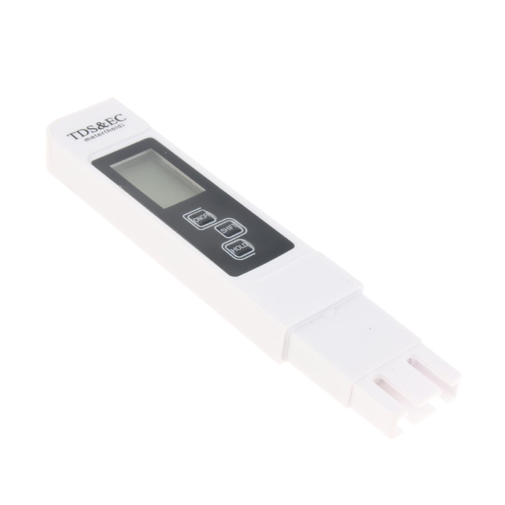
 wet crystal

Maker Pro
Interface an Android smartphone with an Arduino via Bluetooth to control an LED from your phone.
Maybe this helps you
north stream
I doubt the code for that RGB LED controller is available publicly. However, they're made in huge numbers if you wanted to get another one. If you wanted to re-implement whatever patterns it does, it's probably not too tough to re-create them with another board.
 plush field
Hi.
Do anyone know if there is a lib for arduino to read Atmel MaxTouch chip output from i2c.
I think about buying Dualshock 4 trackpad and don;t want to end with useless piece of pcb.
nimble terrace
Hi, where to buy average quality consummable like wires headers boards resistor etc ... ? The cheap option often fails :/
north stream
I tend to get stuff like that from AdaFruit, SparkFun, and Tindie
north stream
For resistors I use a lot, I tend to just buy them from DigiKey. For example, for ordinary 1/4W 1kΩ through-hole resistors, part number 1.0KQBK-ND lets me buy 100 for $2.58.
nimble terrace
ok thx, digikey has nice warehouse !
sparkfun has great tutorial, i might consider that too 😃
torn frigate
hey, how would I write a repetition time?
like if I want to print & execute x every 1 hour
nimble terrace
you can use millis() to get milliseconds since arduino start
or you can use wifi, but best is an RTC module with battery to get reliable time
wide lark
@torn frigate delay(x * 1000 * 60 * 60);
(that's not a recommended way to do it, but it'll work)
if you do that, you block execution of everything else for a very long time
better idea is track how long things have taken and fire your doDiscord() method then
rather than call delay() within it
torn frigate
it worked!! thank you, done it void doDiscord() { sendDiscord("**Temperatura: **" + String(dhtTempC) + " °C"); delay(1 * 1000 * 60 * 60); doDiscord(); }
nimble terrace
is having a counter based on millis a good alternative to delay ?
wide lark
@nimble terrace most definitely: delay literally stops everything in the system the entire time it is “executing”. That’s why I included the caveat: the method “works”, but it’s probably the worst way to accomplish that goal.
 river venture
is that ac power?
if its just low voltage dc its prob ok
well also are you planning to use it outdoors?
@nimble terrace tagging you so you know someone replied
river venture
@nimble terrace so its 120v ac? i would switch to screw terminals and tbh i would also use a grounded metal box
also i would put a fuse in there
i am not sure what the connectors on the sides are, but you dont want bare copper exposed there, or anywhere really
if you want to be really safe with it, you could get an inline GFCI thingy
thatll help save you if something goes wrong
nimble terrace
220v ! connectors are wago
river venture
oh dang
nimble terrace
a fuse is a nice idea !
river venture
yeah def switch to a metal box and use screw terminals
and ground it all
plus make sure all your pcbs are screwed in place
i would also get some sort of strain relief for any cables leaving it and use jacks that dont require ac wires on the outside of the box
220v is no joke
typically i wouldnt recommend diying anything with 220
also quadruple check that the relays can handle 220
nimble terrace
It wont power more than 500w
river venture
honestly 220 can still legit kill you if you mess up
nimble terrace
the wago can handle 450v 32 A
river venture
now as far as the device it self, that seems like a good enough rating
nimble terrace
but yes I m carefull, i ll ask advice at my local shop too
river venture
yeah def go in and ask at a hardware store/hacker space or maybe call a local electrical union and see what they say.
but a commercial ac relay box is going to be a metal enclosure, with an input fuse, and a fuse on every output
also every conductor will be very secure
cause if a 220 ac line falls off and touches your signal line, it can mess you up for real
i personally would never diy a device like this
nimble terrace
I plan to rewire it, with better colors, length, and separate the connectors / boards / arduino
I m new to that 😃
thx for your advices !
put a on/off button and fuse, check grounds
river venture
stay safe, dont take any of this lightly. gotta say im still pretty worried about diying mains
on our jobs we dont touch it at all, we have an electrician run the ac in to our boxes and they attach it to the board
nimble terrace
yeah i m not in hurry
my first solder attempt was dirty but it was for 5v. Here it is completly different
river venture
man i gotta say, i am legit worried. 220v is seriously enough to kill you. i feel like you should really not play with 220v if you are new to electrical stuff
nimble terrace
I know that, that is why I ask
river venture
i know thats going to be disappointing but i think you should really consider buying a premade device that is fully enclosed and properly rated for this