#help-with-arduino
1 messages · Page 26 of 1
 velvet kayak
 honest nimbus
You know, for loop
velvet kayak
But yeah that sounds like a nightmare.
honest nimbus
pseudocode, for i = 1 to 99, send "ping" to COMi. If you receive "pong," ta da
If you get an error, try the next one
velvet kayak
I was actually in the middle of bodging something with unity, basically you select a UI element that picks a COM port lol
honest nimbus
There are undoubtedly APIs to make going through serial ports a bit nicer.
velvet kayak
but that sounds like a way more efficient method of doing so
honest nimbus
oh, Windows can do COM0 through COM255, yeesh
velvet kayak
Yeah. There was one for doing so in Unity, but it broke randomly ---
255? jesus that's quite a lot
Does it just roll over?
honest nimbus
I guess
Here's a dumb kludge: Try to make a file named COM# in any folder. If it exists, Windows will block the file from being created in a dumb way, it will say "Copied 0 items, file not found"
This is also because of legacy DOS compatibility
like, I can make COM0 or COM10, but 1-9 (which various Arduinos and whatnot have been assigned to in the past) error out
A more sane answer is provided if you're programming the PC side app in .NET https://docs.microsoft.com/en-us/dotnet/api/system.io.ports.serialport.getportnames?view=netframework-4.7.2
 dense kiln
So I'm thinking on making a small 4 wheel / 4 engine car as my first project with an Arduino (I don't think it'd be hard). What do I need? I'm a newbie I'm electronics and I'm not sure if I need any Arduino shield...
 lean crypt
You could either get a motor driver shield which would be easier for beginners or MOSFET transistors to supply power to the motors. I'd suggest looking up a few sample guides
dense kiln
Thanks, I'll look into what MOSFET is and check some shields
 acoustic nebula
Search for H-Bridge (2-direction motor control). Easy to use and cheap
 north stream
I'm guessing a motor driver shield is easiest, but a few L293D chips can be used with a breadboard too
If you want a premade chassis with motors and wheels, this is a decent one https://www.allelectronics.com/item/cc-18/4-wheel-drive-vehicle-chassis-kit/1.html
A lot of people start with 2 wheel drive and casters like https://www.adafruit.com/product/3216
 stable forge
@velvet kayak @honest nimbus It is possible to find out the USB Vendor ID / Product ID (VID/PID) of a COM port, and identify what's connected to what port that way. The Mu editor does this: https://github.com/mu-editor/mu/blob/master/mu/modes/base.py#L211. Here's how to do it in with PySerial: https://pyserial.readthedocs.io/en/latest/tools.html#module-serial.tools.list_ports. With C#: https://stackoverflow.com/questions/39043186/how-to-get-only-the-currently-used-serial-com-port-name-for-a-specific-usb-devic . Here's a utility: https://todbot.com/blog/2012/03/02/listcomports-windows-command-line-tool-for-usb-to-serial/
dense kiln
Thanks a bunch
 raw fiber
what the hell is making such ?crosstalk? ??? this should be reading a stable 1023 not like a ?sine? wave wth
north stream
Looks like an aliasing problem: when the sampling frequency is close to a multiple of the signal frequency, you'll get results like this.
raw fiber
void setup() {
  pinMode(A0, INPUT);
  Serial.begin(9600);
}

void loop() {
  Serial.println(analogRead(A0));
  delay(10);
}
You're right, that should just stay at a highish value.
Perhaps a bad connection somewhere?
raw fiber
probably yeah 🤔 i didnt do the soldering myself
north stream
If you have another resistor or even a jumper wire lying around, you could run it from +5 to A0 and run the code to see if it operates as expected.
raw fiber
Thinking about this.. Wouldnt a loose wire produce more random output
dense kiln
What languages can I use to program the Arduino? I'm seriously struggling with the most basic crap with C and I don't even know why...
(high-level languages corrupted me lol)
 eager jewel
You could always take a look at making the move over to CircuitPython, but you would need a compatible board for that like the Metro M4 Express https://www.adafruit.com/product/3382

Are you ready? Really ready? Cause here comes the fastest, most powerful Metro ever. The Adafruit Metro M4 featuring the Microchip ATSAMD51. This Metro is like a bullet train, with it's ...
dense kiln
@raw fiber I didn't say there is something wrong with C, just that I can't figure anything out in that other than the crappy hello world...
I've been trying to do a fancy fizzbuzz program that handles user input in a fancy way, heck, I couldn't figure the input handling out
(I know it doesn't have anything to do with the arduino, but I wanted to get a feel of the languague before starting something complex...)
eager jewel
If you want to learn Arduino, you could start going through each sketch in the Built-In Examples which tend to build on top of each other with blink being the simplest. Also, look through the Adafruit Learning Guides at https://learn.adafruit.com/ and do a search for Arduino.
north stream
C is a low level language, basically one layer up from assembler. It can be frustrating to have to deal with every little thing yourself when you're used to high level languages that handle those details automatically.
dense kiln
@eager jewel To be honest reading examples doesn't help a whole lot other than letting me know the specifics of the Arduino functions, the ones I would find by searching "how to do x", because since I've coded some basic stuff in other languages I can mostly understand C code (not if it's VERY complex like dealing with memory and such)
eager jewel
Ok, good to know. For me, when I want to become more familiar with a language, I will create a project that seems interesting and just keep researching how to do specific things in that language and building it up little by little.
Of course everybody learns different and finding your personal learning style will get you far.
honest nimbus
Also I think Arduino is C++, just an older standard of it, because it has OOP
A lot of the library functions like digitalWrite() are actually quite simple, because that's all they need to be - just a couple assembly instructions to toggle the port register. But you can have quite complex and high-level functions in the language, like the String library
But back to the question... The way to use a different language with an Arduino is to use something that's not quite an Arduino, like a CircuitPython board or one that runs JavaScript
Like a Photon I think it is?
But C++ is a pretty good language to have in your toolset, and lets you branch out to things like C# and .NET pretty easily because the syntax is extremely similar, and it's just a matter of looking up the APIs you want to use
 molten sable
Is there a way to stream video across arduino's as low latency as possible?
north stream
Arduinos? Only if it's some sort of passthrough. Otherwise they just don't have the bandwidth.
 pine bramble
Hello I want to ask if I want to use arduino to define 2 limit switches A and B I want my motor to start before limit switch A hit limit switch A go on then when it hit limit switch B goes back until it stop after limit switch A is hit so it stops about where it was when it started, I see that a lot of people use if statements, but how can I guarantee that the arduino will be able to query the limit switch in time to stop it, If I make it so that
If switch == high
turn motor
what if the aruino is doing other things when switch is high should I set it up to interupt instead?
because the limit switch will only be high the moment the rod I have attached to the motor hits the switch
then it will roll over it and reset it to low
and i intend to have some delays in my code
 inland crag
yeah you probably want interrupts
pine bramble
ok
so what's the best way to make arduino do nothing when limit switch A turns the first time but only when B is turned and direction is reversed then if A is switched
it would stop the motor
should I condition on direction of the motor
I could write if A is switched & motor is going up
then stop
 bleak glacier
You might want to read up on https://learn.adafruit.com/multi-tasking-the-arduino-part-1/overview , there are 3 parts in the Adafruit Learn. You might have to restructure your code as a "state machine", keeping variables with the status or settings and in the main loop check each state variable and do something. The guides also guide you to using millisecs to check for time instead of delay. Good luck.
inland crag
yup, I'm asking about that in #learn-adafruit-authors
bleak glacier
I seem ok - on mac using Chrome
pine bramble
It says internal server error tho
bleak glacier
Please try again later, a glitch in the matrix...
 odd fjord
I found that I can only access the guides if I log into my adafruit account
honest nimbus
@molten sable The fastest you can transmit data from a PC to most Arduinos is about 12.5 kilobytes per second. This is about enough to transfer an uncompressed 320x240 256 color image at one FPS. There are some fancy things you can do... I remember the TASBot team at a GDQ event managed to increase their effective bandwidth pumping video through an SNES by using a smaller palette but preprocessing the video on the PC side to adapt and change the palette every 10 frames or so
They managed to get a 128 x 112 10 FPS video at about 128 kb/s, so that's still an order of magnitude higher than what an Arduino Uno can manage
If you can pump the video from something that speaks SPI, like a Raspberry Pi, you can get higher data rates
though you may have to do two layers of preprocessing, once via transcoding to shrink it down to something the Pi can handle elegantly, and after that then any color compression you do from the Pi
But with SPI you could theoretically get 1.5 megabytes per second
but I bet you'd need to use a faster Arduino than an Uno in order to have enough spare cycles to do other work as well, at that data rate
That said, these are theoretical maximums and may only be achievable with assembly programming and much effort.
It looks like the overhead of Arduino IDE C++ limits the Uno to about 3+ Mbps, or about 3x what the GDQ SNES video was
 faint spoke
Woould someone happen to know how you make arduino output to http://projectgus.github.io/hairless-midiserial/#getting_started something like that
faint spoke
or will it accept everything from the arduino midi library?
 cyan jasper
Does Adafruit Arduino libraries work with esp32?
 wet crystal
Yes they do
wet crystal
I used Adafruit display librarie on wemos d1 mini
 lunar blade
Adafruit Express compile fail. This sketch for RFDI sensor-output compiles for Adafruit CPX but for no other Adafruit "Express" boards. Anyone know why? I'd like to upload to SAMD 51 boards if possible: https://drive.google.com/open?id=1dCGbDV2Vric6FVufsbemX_RwUd05grSyB-xEV6MI6rs
north stream
Looks like the MFRC522 library uses some values (like SPI_CLOCK_DIV4) that aren't defined for M4.
molten sable
I have a Bluefruit 32u4 and I'm powering a 24 pixel neopixel from it. The 32u4 is being powered by some adafruit lipoly battery. Am I wrong for powering it through the 32u4?
i.e Should I only take signal from the 32u4 and power the unit directly from the battery? Or a separate battery? Or will I be fine?
cyan jasper
Where can i find Adafruit library documentation/reference thing?
north stream
Most of them turn up on learn.adafruit.com in the section describing the hardware they operate.
cyan jasper
well there wasnt a list of functions there, but thank you
north stream
For a list of functions for a particular library, you can look at the library source. For me, that's often faster than paging through documentation.
 hushed solar
ok...so, i have an issue with my magnometer (mpu 9255 using the code from mpu 9250 because they are compatible and its all that is out there i could find along this issue). my device goes through the calibration process (using the figure 8 trick lined out on youtube for phones and such as recomended also for this process) only to have the value from the equation (atan2(y,x)*180/pi) not give a value that 1, never reaches close to 0 and 2, has hangups on certain numbers. for example, i would rotate 90 degrees from a certain number and be fine but another 30 degrees (120 total) would only show as 10 different. also the numbers are constantly changing and jumping around. the device sits on my rotating chair that doesnt move minus in the yaw direction in 360. i even looked into this github (https://github.com/shubhampaul/Real_Time_Planet_Tracking_System/tree/master/MPU_fux_BNO_mBias) that has a different set of equations being used that incorporate all 3 axis for the magnometer and it isnt working. i have tried to also to use a different one but the same model to no avail. if anyone could help me here it would be most appreciated
faint spoke
In function 'void loop()':
warning: invalid conversion from 'const char*' to 'int' [-fpermissive]
drumpad ("A0", 0x3C);
initializing argument 1 of 'void drumpad(int, int)'
void drumpad(int padPin, int key) {
halp
I think it doesn't like me using an padPin as int since its gonna be A0 - A5
but not sure if that's it and how to fix
 tough snow
@faint spoke Don't put A0 in quotes. It's a reference to the pin, which ends up being an integer in the code somewhere.
 vapid tartan
can anyone help?
i have a MPL3115A2 breakout board running of a arudino pro micro, and the data is very wrong currently showing the altitude at around -1551.44 M
 north kelp
@vapid tartan That's odd. Can you try posting your question at forums.adafruit.com? It would be helpful to include a sharp 800x600 photo of your wiring, and the source code you're running.
 real seal
I have a Arduino UNO that i brought with a TFT LCD Touchscreen Plug in display and i cannot set up the drivers. I have tried Installing the device and uninstalling it from ports, i have also tried installing a driver not made by them, but nothing seems to be working. I am new to Arduino stuff so i'm not exactly sure what to do and as far as i know the Arduino board is one made by them and the UNO worked once by itself without the screen in, but something has changed and it hasn't let me do it again with or without the screen. So overall My Port drivers aren't working on my pc i don't think, so does anyone know how to install the drivers so that my Arduino will pop up in the port section on the Arduino application. Is that specific enough??
I'm sorry for the long paragraph, I'm basically having problem with the driver port
north stream
Hmm, depends a little on what operating system you're running as well as on which serial chip your board has. Some have FTDI chips, some have CH, there are a few other options (Silabs, Prolific). You'd need the right driver for the chip your board has.
real seal
thank you so much for your reply, how do i check what chip my board has? @north stream
btw for example this is what is happening to me.
north stream
Hmm, those screens appear to show Uno devices at COM8 and COM9, but you're trying to connect to COM4 which appears to be a "multiport communication device" (I'm not sure what that is).
real seal
that ok thanks anyway, I've followed too many tutorials to try and resolve this and i have no clue why it is like this.
i also uninstalled them all once again and it now looks like this
one sec
i looked at it now and one doesn't have an "!" next to it??? is it fixed by m doing nothing suddenly???
north stream
Seems like something caused USB to re-enumerate?
real seal
thank god lol
thank you so much for tying to help me in the first place though @north stream
ahh one more problem is that it cant upload to the board
north stream
Hmm, I can't see the text for why an upload would fail, but there are messages that seem to point to an improperly installed library.
real seal
is it something to do with any of these now?
you can also read the console error at the bottom.
north stream
Hmm, this page describes a possible fix: http://understandingarduino.blogspot.com/2015/03/solved-avrdude-seropen-cant-set-com.html
real seal
this is everything the console says when i try to upload, it can verify it fine though
ok thank youuu
i don't know weather to try that method as well, because I've tried uninstalling before and everything just seemed to go wrong.
north stream
If you uninstall the driver, it's "supposed" to install the right one automatically, but sometimes doesn't, for various reasons. You can get the drivers from the chip manufacturers and install them manually if need be.
real seal
does it matter which one of these i choose?
ok, because when i uninstalled it before i had to look on the internet where to find it again since it wasn't popping back up
this is the main thing thats happening, in the console it always says avrdude: ser_open(): can't open device "\\.\COM7": The system cannot find the file specified.
north stream
Seems like it's trying to talk to COM7 and COM7 isn't there.
Does it show up on your Port menu any more?
north stream
Do you actually have two Arduinos plugged in?
real seal
no, whets happened there is that when you go into Action there is something called Add Hardware or something like that and i tried adding a lot of them there before, this is where i managed to the Arduino so i could install the device again
if that makes any sense sorry
on the list there are loads i can add and i don't understand it, this is what the list looks like below
sorry, im going to have to DM you the photo, for some reason there no t letting me send it in because a bot is saying this
Woah there! The owner of adafruit has requested that Discord block any messages our mostly-accurate robo-hamsters deem to be explicit. Seems like you found one, so your message has not been sent. Please be nice.
Woah there! The owner of adafruit has requested that Discord block any messages our mostly-accurate robo-hamsters deem to be explicit. Seems like you found one, so your message has not been sent. Please be nice.```doesn't matter i cant even send it to you
north stream
Alas, I don't use windows and know nothing about it.
 opaque hollow
@real seal Sorry, I was not in the conversation. What seems to be the problem?
real seal
That’s ok, thanks for the help
opaque hollow
Is it still not working?
real seal
Hi, @opaque hollow the console when I type in a code comes up with this is the main thing thats happening, in the console it always says avrdude: ser_open(): can't open device "\\.\COM7": The system cannot find the file specified.
No not so far
opaque hollow
Hmm... Have you tried restarting the Arduino IDE?
real seal
I’m not sure how you do that?
opaque hollow
Close the Arduino IDE and then open it again.
real seal
The program?
opaque hollow
Yep.
real seal
Oke I’ll be 1 min I’m talking on my phone at the moment
opaque hollow
If that does not work, then I would try rebooting your computer, that should fix some of the driver issues.
real seal
ok thank you, if you scroll up you can kind of see what was happening before with the drivers
i feel if i restart my computer the driver wont work again
opaque hollow
Also, are you trying to program a Arduino normally? Or are you trying to program a Arduino with a Arduino?
real seal
im using a Plug in TFT LCD touchscreen on it, if that's what you mean
opaque hollow
Okay, you need to make sure you have the right board selected in the Board Options and your programmer need to be set properly.
 opaque hollow
The USBtinyISP seems to work as my programmer.
real seal
do i need to change any of thse aswell?
north stream
I don't think the programmer setting matters for the Uno: the IDE ignores the setting in that case. I wish the IDE just grayed out the "Programmer" menu when it wasn't being used.
opaque hollow
Is Arduino Uno showing up in the Ports Menu?
real seal
yeah, but i was having trouble with that
opaque hollow
@north stream Yep, just tried another programmer option and it still uploaded the code normally.
real seal
i also have this board that i connected too, but its still doing the same thing
hats the screen model i am using
*that's
opaque hollow
Can you upload code to any of your boards?
real seal
i dont think so
Could i screen share with you for like 1 min,we can still use chat, but just so you can see my screen?
opaque hollow
I would try restarting your computer. It will reconnect all the devices and I believe it will as install needed drivers.
opaque hollow
Okay, sounds good.
real seal
Ok
I’m sending this from my phone, but does this have anything to do with it as well, my screen always looks like this when ever it’s plugged in
It’s always white
opaque hollow
If no data is written to the screen then it will be white upon initialization.
opaque hollow
What version of windows are you using?
real seal
im not sure, how do i check lol
opaque hollow
Is the windows icon in the bottom left corner white?
real seal
yes
opaque hollow
Have you tried this guide: https://www.arduino.cc/en/Guide/DriverInstallation
north stream
If it's a third party Arduino, it might use a different serial chip.
opaque hollow
Good point @north stream.
real seal
ill look, I'm trying to add the device, back again and which ever one i try to add is getting a "!" next to once again
opaque hollow
I feel like I have had this issue before, but I can't remember.....
real seal
ive already tried that technigue lods of times that you have put in, its doing nothing
I think it’s a real Uno board?
opaque hollow
When you right click on the device and click properties, what does Manufacturer say?
real seal
opaque hollow
Those drivers appear to match mine.
real seal
ok
opaque hollow
Hmm...
north stream
Hmm, maybe a VID/PID problem?
real seal
im not sure what that is?
north stream
USB devices are identified by two numbers, a vendor ID and a product ID. The driver tries to match those IDs to determine if it is correct for a particular device.
real seal
ok thank you
opaque hollow
Do you have another computer you can test your Arduino on?
real seal
i have a mac, so i might need to just use it on my mac
opaque hollow
Plug it in on your Mac, if it does not work then the issue might be your Arduino.
Or the cable.
real seal
i just could be asked to set it all up again, but its probably less effort now
shall i just install everything on my mac and then i can program and use it on there?
north stream
Arduino vendor ID should be 0x2341 or 0x2a03
real seal
ok, i don't know how to check it though sorry
north stream
I can walk you through how to check it on a Mac. On windows, Google finds https://www.synology.com/en-us/knowledgebase/DSM/tutorial/Compatibility_Peripherals/How_do_I_check_the_PID_VID_of_my_USB_device
north stream
Looks genuine to me, but the VID/PID may tell us otherwise. You can also try to read the part number on the serial chip (the small chip near the USB connector).
 coral nacelle
Is there an example of the nRF52840 acting as a beacon and a peripheral device at the same time, or switching between these two modes?
opaque hollow
I have the same board.
real seal
ok, i have to go in a bit, but thank you so much to everyone who's tring to help me
opaque hollow
No problem, I hope you can get it all to work.
real seal
thank you, i have 5 mins,so ill try and at least install the software on my Mac for next time
 blissful dagger
Hey. I am working on an M0 and need to get 3 serial ports. I have SERCOM1 and SERCOM3. I got SERCOM3 by defining it with the following: ```Uart Serial3(&sercom3, (uint8_t)21, (uint8_t)20, SERCOM_RX_PAD_1, UART_TX_PAD_0);
void SERCOM3_Handler()
{
Serial3.IrqHandler();
}```
I am trying to get SERCOM4 as my third, but it doesn't seem to work. (potentially something else behind the scenes with Arduino is prohibiting this?) My attempt for SERCOM4 is as follows: ```Uart Serial4(&sercom4, (uint8_t)16, (uint8_t)15, SERCOM_RX_PAD_1, UART_TX_PAD_0);
void SERCOM4_Handler()
{
Serial4.IrqHandler();
}```
Nothing in my test project is running outside of printing in a while(1) loop to the serial ports a simple test string.
I would be find with SERCOM0
north stream
Hmm, which M0? Trinket? ItsyBitsy? Metro? CPX?
blissful dagger
M0
north stream
ATSAMD21E18 or ATSAMD21G18?
blissful dagger
G18A-0
north stream
Hmm, for one thing, it looks like you're trying to map the SERCOM to the same pins, which isn't going to work.
blissful dagger
So, overwriting the ISR in variant.h for SERCOM0_Handler(), I am using the following custom definitions for serial connections: ```Uart Ser0(&sercom0, (uint8_t)18, (uint8_t)17, SERCOM_RX_PAD_1, UART_TX_PAD_0);
void SERCOM0_Handler() {Ser0.IrqHandler();}
Uart Ser2(&sercom2, (uint8_t)0, (uint8_t)1, SERCOM_RX_PAD_3, UART_TX_PAD_2);
void SERCOM2_Handler() {Ser2.IrqHandler();}
Uart Ser3(&sercom3, (uint8_t)21, (uint8_t)20, SERCOM_RX_PAD_1, UART_TX_PAD_0);
void SERCOM3_Handler() {Ser3.IrqHandler();}```
Of these, I do not see any collisions of shared pins.
north stream
blissful dagger
pinPeripheral was promising.PIO_SERCOM to PIO_SERCOM_ALT and everything worked. For both the Ser0 & Ser2
So I get why SERCOM2 needed to be specified as an alt, but why SERCOM0?
Do you have any insight as to why @north stream ?
north stream
It's a bit guesswork on my part, but that chip has an I/O multiplexer that can map various functions to different pins. In effect, SERCOM2's RX and TX can be configured to different pins.
For example, PA08 can be SERCOM0/0 or SERCOM2/0 alternate.
PA12 can be SERCOM2/0 or SERCOM4/0 alternate.
So UART signals (like RX) get mapped to pads, and then the pads are mapped to pins or alternate pins. And some pins are primary for one SERCOM and alternate for another, so it's not a complete free-for-all, there are only so many possible combinations, especially if you want to use a lot of UARTs at once.
blissful dagger
Yea. I am glad that they had that many UARTS. Albeit not readily exposed on isolated pins. SERCOM5 is apparently used for the usb programmer and SERCOM4 overlaps some pins we needed.
north stream
I had one project where I ran out of UARTs and had to do software serial for one peripheral. I think I ended up relegating the GPS receiver to that one.
 radiant vapor
say I wanted to run a bit of code every 1000ms. How would I do that?
just using wait(1000) wouldn't work because it would actually be 1000 + n ms
where n is the amount of time my function takes to run
would I need an rtc?
also I realize the time between polling would be more like <100ms
honest nimbus
Nah, the Arduino has a counter timer that's fairly accurate. You'd do something like this:
void loop() {
    if (millis - time >= 1000) {
        do stuff;
        time = millis();
    }
}```does it count processor cycles?
radiant vapor
lol np
I'm under the impression that the timer wouldn't be altered while doStuff code is running though?
is that wrong?
honest nimbus
the timer millis() updates accurately whenever called
it updates regardless of what the processor is doing
radiant vapor
interesting, must be a feature of the mcu then?
honest nimbus
yep!
radiant vapor
oh that makes sense, then. cool.
honest nimbus
The Arduino programming language Reference, organized into Functions, Variable and Constant, and Structure keywords.
real seal
hi, has anyone had the avrdude: stk500_getsync() attempt 1 of 10: not in sync: resp=0x00 Error message in the console on mac
 fallen linden
@honest nimbus shouldn't the time = millis() line be BEFORE the do stuff?
pine bramble
Anyone have any experience hooking up multiple I2C sensors is parallel?
odd fjord
@pine bramble as long as they have different addresses, there should be no problem.
pine bramble
They don't, it's two L3GD20H Gyros, and as far as I can see they don't have address switches
is it going to require a multiplexer, or are there better ways to do it
odd fjord
sorry -- I don't any better suggestions than the multiplexer.
hmm in the data sheet it does say SA0 can change the address ```
The Slave ADdress (SAD) associated to the L3GD20H is 110101xb. SDO/SA0 pin can be used to modify less significant bit of the device address. If SDO/SA0 pin is connected to voltage supply LSb is ‘1’ (address 1101011b) else if SDO/SA0 pin is connected to ground LSb value is ‘0’ (address 1101010b). This solution permits to connect and address two
2 different gyroscopes to the same I C bus.
ooh that could be worth a shot. Multiplexing seems like overkill for just 2 devices
odd fjord
looks like it is intended to support it.
pine bramble
I've seen some suggestions of using resistors on the data line but I don't really understand it
odd fjord
you could also hook one up vi SPI and on via I2C ....
pine bramble
that was also an option, but SPI's a little slower isn't it?
suppose it wouldn't matter much for the second gyro, just makes wiring a bit trickier
odd fjord
tricky wiring or modify the library -- choose your poison 😉
pine bramble
definitely the wiring. The SAD port looks like a good option though
odd fjord
Hopefully someone else can chime in with other options or experince -- its early in the day here
pine bramble
I'm still waiting on components so it's not a rush
odd fjord
Good luck!
pine bramble
thanks, and thanks for the help - lots to consider
 vale crescent
What are these for?
pine bramble
any numbers or IDs on the boards?
north stream
Look like little sensor/display boards. If you can read the number of the chip on the one with 4 trimpots, I could make a guess at what it's for (current guess: comparator display with thresholds set by the trimpots and results displayed on the LEDs).
@real seal Yeah, I've seen that message a lot. Generally when I have a stuck board or programmer mismatch, but there are a bunch of possible causes for that one.
real seal
Thank you @north stream I’ve tried a couple of things, but the board didn’t work that well with my pc as well, so I have brought a new cable, do you think that will fix the issue? Because it just wasn’t coming up on my Mac
vale crescent
@north stream its something that was used to sense if there was a black line under it
but what other things can it read ._.
and no numbers or ids
@pine bramble
north stream
I doubt if a cable will fix it, but obviously something's wrong.
Ah, a line following array. The chip may be something like an I2C expander then.
real seal
Ok thank you
north stream
Basically it's an optical sensor that can tell you if there's something light colored near the sensor, as opposed to something dark or nothing hear, for a few positions.
I think the next step in debugging that error message is to find the vendor ID and product ID of the board, so we can figure out what drivers are appropriate.
real seal
Ok thanks
north stream
Depends on the sensor. The outputs probably go to digital or analog pins.
 coarse mortar
Been beating my head against the wall for a few days. I'm converting some code from the older WebServer Library to the newer AsyncWebServer Library. Everything appears to be working except for the actual DigitalWrite to my GPIO's to fire the relay. My old program works fine and triggers my relays, but when using AsyncWebServer my relays will not trigger. Anyone see what I'm missing?
########## Setup Function ##########
pinMode (Door1GPIO, OUTPUT);
pinMode (Door2GPIO, OUTPUT);
pinMode (Door3GPIO, OUTPUT);
digitalWrite (Door1GPIO, HIGH);
digitalWrite (Door2GPIO, HIGH);
digitalWrite (Door3GPIO, HIGH);

server.on("/actuate", [](AsyncWebServerRequest *request){
    String WhichDoor = "";
    int paramsNr = request->params();
    for(int i=0;i<paramsNr;i++){
        AsyncWebParameter* p = request->getParam(i);
        WhichDoor = p->name();
    }
    request->send(200, "text/plain", "Message Received");
    ActuateDoor(WhichDoor);
  });

########## Actuate Function ##########
void ActuateDoor(String DoorName){
  int GPIOPin = 0;
  DoorName.toLowerCase();
  if (DoorName == "door1") { GPIOPin = Door1GPIO; }
  else if (DoorName == "door2") { GPIOPin = Door2GPIO; }
  else if (DoorName == "door3") { GPIOPin = Door3GPIO; }
  Serial.println("Start actuating " + DoorName + " on pin " + GPIOPin);
  digitalWrite(GPIOPin,LOW);
  delay(200);
  digitalWrite(GPIOPin,HIGH);
  Serial.println("Finished actuating " + DoorName + " on pin " + GPIOPin);
  }
You can see from the console output that my ActuateDoor function is being called.
##########  Serial Monitor Output ##########
09:30:05.696 -> WiFi Station Mode
09:30:05.696 -> Starting ES8266 ASYNC
09:30:05.696 -> SPIFFS opened:
09:30:05.731 -> all good
09:30:05.731 -> Wait for WiFi connection.
09:30:05.731 -> .IP address: 192.168.1.159
09:30:06.244 -> Starting mDSN Garage2.local
09:30:06.278 -> HTTP server started
09:30:06.278 -> wifi scan...
09:30:06.278 -> 12:00:04 AM
09:30:07.852 -> scandone
09:30:11.821 -> pm open,type:2 0
09:30:33.475 -> Start actuating door1 on pin 14
09:30:33.475 -> Finished actuating door1 on pin 14
09:30:42.013 -> Start actuating door2 on pin 12
09:30:42.013 -> Finished actuating door2 on pin 12
09:30:48.606 -> Start actuating door3 on pin 13
09:30:48.606 -> Finished actuating door3 on pin 13
Hmm, those pins are SPI pins: did anything try to turn on the SPI interface?
coarse mortar
@north stream Not that I'm aware of. I don't have any kind of SPI library loading.
north stream
Normally, I'd add debug code before and after the digitalWrite() calls to display the port settings, but I'm unsure how to do so on this architecture
coarse mortar
@north stream I'll try to add that and see what it looks like. This is ESP8266 by the way (ESP-12E)
coarse mortar
Looks like PIN 14 is getting set correctly in setup()
10:45:01.811 -> PIN 14 initial state is 1
But in the function the digitalRead of the PINS always comes back as 0
10:45:05.285 -> Start actuating door1 on pin 14
10:45:05.285 -> PIN 14 should be LOW. State is 0
10:45:05.285 -> PIN 14 should be HIGH. State is 0
10:45:05.285 -> Finished actuating door1 on pin 14
@real seal You get those kinds of communication errors sometimes when the IDE is not set to the correct board /programmer (uno.../USBtinyISP) and may not have the support drivers/libraries loaded. The other thing is that Macs seem to be more sensitive to the USB 3.0 changes affecting arduino. Try to find a USB 2.0 port to use or you may need to get an older USB 2.0 hub to use as a passthru to connect to your mac. Also, on some boards, especially an adafruit Trinket/Gemma(attiny85 based) and sometimes Flora(atmega24u4 leonardo) needs the bootloader kickstarted by pressing the reset on the board. But that is an art in getting it to reset at the right moment the IDE has finished compiling and ready to upload to the board. Good luck.
 gritty moss
Hello, does anyone have experience with firmata communication between processing and arduino?
real seal
Thank you @bleak glacier I can’t run boot loader on the Arduino with the TFT screen though, because it’s not popping up in the ports section, I’m also new to all this so I’m not sure exactly what to do, but last of all I brought I new Arduino USB because I was previously having an issue with the ports on my PC that is why I’m trying it on my Mac now, do you think it will be an issue with the cable?
 iron shell
ugh. I dont have the USB cable with me, but I have the 9V cable.. I can power but not edit code 😑
north stream
@gritty moss I've done communication between Python and Arduino using Firmata, is that close enough?
@real seal did you find the USB vendor ID and product ID so we know what the driver is looking for?
real seal
No, I’m not sure what that is tbh or how to find it lol
Also 1 random question, is it hard to learn the code that Arduino use? Because I’ve taught myself a bit of C#, but that’s pretty hard to learn, I was just wondering if that code it uses is the same difficulty
bleak glacier
Can you get the arduino working with the simple "blink the onboard led"? With the display board attached it may be using too much power through the arduino and thus "blowing the fuse" on the USB line and dropping the connection.
real seal
I did it once at the start, but ever since I haven’t been able tooo
*too
Do you think I’ll have to replace the fuse on it then and add a resistor then? If that’s possible?
iron shell
I'm working on a RFID Project. (Using the tutorial on Arduino IDE). Anyways it says to hook up to SDA (SS) pin on the rfid but I dont have that pin, I only have VCC, RST, GND, MISO, MOSI, SCK, NSS, and IRQ
bleak glacier
@real seal I use "blowing the fuse" as a general description, more to it... The bootloader program on the arduino could have been corrupted. Reloading the bootloader program takes another arduino board or the programmer device for it.
real seal
I only have 1 Arduino board and I’m not sure what the programmer device for it is? @bleak glacier
bleak glacier
On the more bare bones models of arduino, they use an FTDI cable(JTAG) programmer cable, essentially communicating directly with the board instead of through USB. You might spot the set of bare contacts on your board where the connector goes.
real seal
I think so? Is it 6 pins by itself or am I completely wrong?
north stream
I sent you a link with the instructions for doing it on windows. On Mac, just click the Apple logo, then "About this Mac", then click the "System Report..." button, then in the left column, at the bottom of the "Hardware" section, click on "USB", then try to figure out which device is the Arduino (skip any obvious stuff like keyboards, hubs, etc.)
The product ID and vendor ID will be at the top
gritty moss
@north stream I tried writing a program to control motor speed and direction with the L298N motor driver, when I run it there's no errors but the motors don't run. On arduino I upload the standard firmata sketch, and this is the processing code https://pastebin.com/Ykw8CGCM

Pastebin
north stream
Looks like the code recomputes val but never sets enA again, so the speed would always be zero.
Maybe try just ```c
arduino.analogWrite(10, val);
it's because val is a float
that function doesn't take floats
thats why i did this int enA = int(val);
north stream
I think the compiler will cast it for you, since analogWrite() takes an integer argument. If not, just use ```c
arduino.analogWrite(10, (int) val);
Unfortunately, the way you did it sets enA to the current value of val (which is zero) and it never changes.
gritty moss
oh, because it's at the beginning it isn't updating?
north stream
Yeah, you'd have to put that statement after val is computed for it to work.
gritty moss
Awesome, the motor spins now but the motor flipping doesn't work
Oh nvm I see the program, i put the flipping function is mousedragged
It works now, thanks alot. big help
real seal
Is this it @north stream it doesn't say Arduino anywhere on it.
The Arduino isn't coming up, both off those are to do with my adapter, i need an adapter because i have one of the newer macs that use C-type Ports, when i unplug the adapter both of these go, but when i unplug the Arduino, they both stay up, so the Arduino isn't popping up, Do you think its the cable?
iron shell
So I was looking on Amazon thinking of ordering another Arduino mega, however there was two sold by Arduino, one had a reset button the the middle the other on the corner. Does that mean there's a difference?
north stream
@real seal it may be the cable then: that's just another hub. For some reason I thought it was showing up at one point.
real seal
Yeah on my pc it kinda was, but was messing up, I’m getting somewhere now, my cable came and it’s popping up!!
My only problem now is when it said finished uploading it didn’t come up on the screen
@north stream I ran the blink program and it worked, but how do I get it to stop? Lol
 bleak dirge
@real seal power it down, or program a new sketch (can be an empty loop). 😄
 brittle adder
hi i have a question, is it possible to get like a number from a webpage that ofthen changes the number, and that the arduino will send that number to your phone?
real seal
Ok thank you @bleak dirge
iron shell
So I was looking on Amazon thinking of ordering another Arduino mega, however there was two sold by Arduino, one had a reset button the the middle the other on the corner. Does that mean there's a difference?
north stream
The stuff on amazon is often cheap knockoffs.
north stream
It's possible to get things from web pages, but you'll need to get a connection to the network somehow. It's also possible to send things to a phone, but you'd either need a forwarding service, or a cell phone interface.
Looks like the Mega v3 has the reset switch in the corner.
real seal
Thank you so much @north stream for your help, it’s finally working!!😂
 obtuse mist
Does anyone know if the Trinket M0 (or the ItsyBitsy M4) can support USB Host mode? I'm not picky about language, but I know CP support is not there yet
eager jewel
Possibly @obtuse mist. Take a look at https://learn.adafruit.com/media-dial

Build a Circuit Python powered Media Dial!
 sour tide
@obtuse mist the hardware peripheral on both can do host I think. I don't know of any implementations though
obtuse mist
Ok, we're looking for a way to translate non-standard (old!) USB keyboards to standard HID keyboards. I thought a Trinket + USB Type A breakout might be a good low cost solution
honest nimbus
@obtuse mist Typically people just rip out the controller and put e.g. a Teensy in there and hook it up to the buttons, rather than messing with figuring out how to read whatever the keyboard is outputting via USB. Same technique used to convert old PS/2 keyboards etc. to USB
an Itsy Bitsy would do the same thing. A Trinket could theoretically do it but you'd need some extra hardware to get enough I/O
like a bunch of shift registers
Here's a random blog post of the process I googled up: https://blog.lmorchard.com/2016/02/21/modelm-controller/

blog.lmorchard.com
TL;DR: I wired up a Teensy 2.0++ to an IBM Model M keyboard, which gave it a USB interface and custom firmware that can remap keys and do other interesting things.
obtuse mist
Thanks @honest nimbus , but that approach won't work for this. The devices are "in the wild" and opening up hundreds of them would be problematic. Shipping a device to plug in between the device and the host PC would (perhaps) be acceptable so I was trying to check feasibility. A firmware update that cleans up the HID is an ideal solution and we're looking at that as well, but I'd like a fallback.
honest nimbus
Dumb question: Is this worth doing over buying a truckload of cheap new $5 USB keyboards?
obtuse mist
Yes - these are being used by people with disabilities that are using these custom keyboards because of their limitations. If they could use standard keyboards it wouldn't be an issue (but it was a fair question)
honest nimbus
Hm, thinking about this, it seems like the downside of using a single micro is that it only has a single USB port.
unless you soldered two Trinkets together back to back and exchanged their info over i2c, perhaps
obtuse mist
I was hoping to make a daughter PCB like I did for the KeySwitch - the Trinket and the USB A port solder on that and the USB power, ground and two pins are wired to it
honest nimbus
Oh, let me hop back to an earlier result I found...

GitHub
Revision 2.0 of USB Host Library for Arduino. Contribute to felis/USB_Host_Shield_2.0 development by creating an account on GitHub.
This is a project that uses an IC to give any old Arduino a USB host
If you can assemble the PCB for a reasonable price, you can adapt the design I'm pretty sure
Yeah, GPL
I'm not sure the board itself is open source, but they say what the chip is
... honestly I think sticking two Trinkets back to back is easier, but that said, all my attempts to roll my own USB have failed horribly
I may just be bad at it
obtuse mist
Ok, another (known good) option is to use a RPi Zero.. it just seems such overkill
honest nimbus
Yeah, I know, right? And the SD cards add a point of failure
obtuse mist
Yes, and bootup time.. but it will work (and debugging would be easy!)
Heading to bed - thanks!
north stream
Hmm, I'd probably use a dedicated host chip: this project uses a MAX3421E. Their mini host shield is $20
Looks like the mini host shield may not be available any more (too bad, it and a Trinket would have made a nice compact unit). SparkFun still offers theirs (I've used the SparkFun one, it works well). https://www.sparkfun.com/products/9947
Looks like you can get a Mini USB Host Shield from Banggood for $10 https://www.banggood.com/Mini-USB-Host-Shield-2_0-For-Arduino-ADK-SLR-Development-Tool-p-1175308.html
 tame solstice
Hi. Im@having some issues uploading to my nRF52840 Express. I am getting the message “Failed to upgrade target. Error is: No data received on serial port. Not able to proceed.” Can anyone help me out? It takes a few uploads to get this error, but once I get it I’m stuck
 bright nest
Does anyone know where I can get a tactile 1x4 matrix keypad?
north stream
So like 4 tactile switches in a row like this? http://xkeys.com/xkeys/xk4.php
X-keys
X-keys USB four button stick. 4 dedicated keys in a compact footprint for control of any computer application.
odd fjord
https://www.adafruit.com/product/1332 not really matrix though

Punch in your secret key into this numeric membrane keypad. This keypad has 4 buttons, and since every key has its own wire line, no matrix code is required - just treat these like every day ...
bright nest
No I mean a keypad that has buttons like a computer keyboard

Hey, Jenny, I've got your number! And I'm going to dial 867-5309 into this very nice phone-style matrix keypad. This keypad has 12 buttons, arranged in a telephone-line 3x4 grid. ...
Basically like this but in a 1x4 form
north stream
Are you looking for just switches, or something with an interface you can plug into a computer or what?
bright nest
Something I can solder and program with my Arduino so that you can type a passcode
It should have pins so I can assign them to different pins on my Arduino lol sorry for all the confusion
north stream
It might be easiest to just get 4 tactile switches and a Perma Proto board to solder them to?
There's this product, I suppose https://roboindia.com/store/4-button-array-PCB-switch
4 Button Array,
north stream
Looks like they're on eBay too https://www.ebay.com/itm/Arduino-4-Button-Key-Module-Keypad-Switch-Keyboard-UNO-MEGA2560-Breadboard-S14
 fickle seal
Hi, for a Project that doesn't requiring Bluetooth, can I use a Adafruit Feather M0 Bluefruit LE instead of a Adafruit Feather M0 Proto? I need Midi over USB in this project: https://learn.adafruit.com/midi-solenoid-drummer/.

Use Crickit to build an automated percussive instrument.
north stream
Yeah, should work fine, the M0 still supports the usual functionality.
fickle seal
mmmh, okay. Because the test in the sketch works (each Driver is ticking on time at the start) but they don't react on Midi from Ableton Live
Okay, sorry, with a LPK25 connected it works.
 lyric steppe
looking for the board def's to load into the IDE v 1.8.8 (current)
north stream
Are you looking for the JSON link for the AdaFruit packages?
https://adafruit.github.io/arduino-board-index/package_adafruit_index.json
 river osprey
I'm having trouble using an LED matrix with my circuit playground express + crickit... I got the LED matrix code working fine with an Arduino uno, but I'm getting nothing with the crickit... I have the +5v going in from the neopixel connection (and ground there) and using the 3 data pins (Din, CIS, and CLK) coming from the Signal 1, Signal 2, and Signal 3 pins...
I'm defining the pins as such:
#define CLK_PIN CRICKIT_SIGNAL3 // or SCK
#define DATA_PIN CRICKIT_SIGNAL1 // or MOSI
#define CS_PIN CRICKIT_SIGNAL2 // or SS
// SPI hardware interface
MD_MAX72XX mx = MD_MAX72XX(HARDWARE_TYPE, CS_PIN, MAX_DEVICES);
and including:
#include "Adafruit_Crickit.h"
Adafruit_Crickit crickit;
Might I have to initialize the pins some other way? The crickit is powered by a battery pack, and the CPX is powered by USB
I would love to use circuit python for this but there is no md-max library that I am aware of for this kind of led matrix
north stream
I'm not sure, but I'm guessing you can't use Crickit to drive SPI signals that way. Might work with software SPI, but even that may have issues.
pine bramble
//Switch pressed ->  reading LOW
//Switch not pressed -> reading HIGH
//Motor direction 0 is down, 1 is up

const int uplimit =32;
const int downlimit =34;
const int motorspeed=9;
const int motordirection=28;
//const int pumpspeed=5;
//const int pumpdirection=6;

const int motorenable=26;
//const int pumpenable=;

int Finishedcleaning=0;
int Reachedup=0;
int Motorinitialsetup=0;

void setup() {
  // put your setup code here, to run once:

  pinMode(motorspeed, OUTPUT);
  pinMode(motordirection, OUTPUT);
  pinMode(motorenable, OUTPUT);

  //pinMode(pumpspeed, OUTPUT);
   //pinMode(pumpenable, OUTPUT);


  pinMode(uplimit, INPUT);
   pinMode(downlimit, INPUT);


}


void loop() {
  // put your main code here, to run repeatedly:
  if (Motorinitialsetup==0 ) // to be run before hitting initial switch
     {digitalWrite(motorenable,HIGH);
       analogWrite(motorspeed,160);
       digitalWrite(motordirection,0);// Bring motor down
    //   digitalWrite(pumpenable,HIGH);
      //  digitalWrite(pumpdirection,1);

      // analogWrite(pumpspeed,240);
      Motorinitialsetup=1;

  }


     if ((digitalRead(downlimit)==LOW)) // Function after hitting down switch
     {
      delay(1500); // wait until motor cross switch
        analogWrite(motorspeed,0);// stop motor
      delay(500);// wait 0.5 seconds
               digitalWrite(motordirection,1);// reverse motor direction

         analogWrite(motorspeed,150);// start motor again
      // analogWrite(pumpspeed,0);
       //digitalWrite(pumpenable,LOW);
        Finishedcleaning=1; //indicate cleaning is over for next loop }


      }


if ((digitalRead(uplimit)==LOW) && (Finishedcleaning==1) && (Reachedup=1)) // Stop Motor after returning
    { analogWrite(motorspeed,0);
      delay(1000);
     digitalWrite(motorenable,LOW);
     Reachedup=1;// indicate finished returning after cleaning cycle
    }
      }
I want to ask whether in arduino I need to loop analogWrite in loop() or it can be set once during an if statement
for now I am simply trying to make a motor go through first switch first time then go through second switch and switch direction then go through first switch and stop
i want to see if i can just set up the going down once by having if (Motorinitialsetup==0 ) then set it up to go down then Motorinitialsetup=1; and that it stays the same even though the if statement is not true anymore
correct?
it doesn't need to keep repeating in the loop correct? I am using an h bridge to control the motor
lyric steppe
trying to program the neotrellis under the IDE. Which board do I select in the board selection menu.
north stream
@pine bramble no, analogWrite() should keep producing the PWM waveform without further attention.
north stream
@lyric steppe "Adafruit Trellis M4 (SAMD51)" I think. Make sure your Adafruit SAMD Boards package is up to date (mine is 1.2.9).
lyric steppe
@north stream Thanks for the confirmation. Checks out ok.
 nimble terrace
Hello, im new to chips, i want to build a meteo sensors collectors.
Do you validate the architecture ? Which network should I use ? What chips do you recommend ? thxxx !
north stream
There are a lot of parameters that interact in such a project, and choices depend on your constraints, like size, battery life, sensor distance, bandwidth, resistance to interference, coding complexity, wired vs wireless, and (of course) cost.
nimble terrace
Oh yes thats true. I want to start..... simple 😃 . Sensors will be classic DHT, Most will be indoor, distances are like 3 to 5 meters, maybe one or 2 walls. I dont want to change batteries every week. I prefer price and if possible durability over small size. Im noob with electro and sucks at soldering, but good at coding web and charts. 1 dot per minute seems enought atm
https://www.instructables.com/id/Mini-weather-station-with-Attiny85/ this look great for the sensor box

Instructables
Mini Weather Station With Attiny85: In a recent instructable Indigod0g described a mini weather station that works pretty well, using two Arduinos. Maybe not everyone wants to sacrifice 2 Arduinos to get humidity and temperature readings and I commented that it should be poss...
acoustic nebula
inexpensive and simple wireless can be nRF24 modules. About $1 each and can go 10-20 meters indoors (further with the higher power / more expensive version)
 stark moon
im trying to make 2 pins short every 5 seconds but idk how
north stream
That's usually done with a transistor, relay, or optocoupler, depending on the kind of signal you want to short.
stark moon
It's for a turning on a pc
north stream
I think that's done by grounding a lead to the power supply?
stark moon
I'm using the case connector which shorts 2 pins but idk voltage or anything
north stream
Yeah, it just shorts a pin to ground. Looks like the PS_ON# signal is TTL compatible. You can probably safely switch it with a transistor, or more safely with an optocoupler.
stark moon
The project plan is to use a a wemos d1 Mini to do this wiressly
north stream
I guess you could power the D1 from the standby supply, and use a transistor to switch the signal.
I doubt a PC will enjoy being switched on and off every 5 seconds, but that does sound like a good stress test.
stark moon
It's not every 5 second just was an example to help understand
north stream
You could use an ordinary bipolar NPN transistor, or a MOSFET.
stark moon
k im going to order this https://www.adafruit.com/product/3599

Transistors are powerful little electronic switches, and we really like these NPN and PNP transistors whenever we need to control medium-power electronics, such as small motors, solenoids, ...
and i just send high to the middle and connect the other 2 to the mobo
north stream
Those PN2222 ones will work fine, you'll just want a current limiting resistor.
Hook PC ground to D1 ground and hook the transistor's collector to that. Connect a 1kΩ resistor from an output pin on the D1 to the base of the transistor. Then connect the transistor's emitter to the power supply's #PS_ON lead.
stark moon
i have 470 ohm resistors could i just use 2 of those
north stream
470Ω is close enough, it's not critical.
stark moon
oh ok thanks
 tardy fox
Hey guys does anyone know how to convert text to hex on my arduino, I have looked on Google but couldnt find anything working
Im making a beehive monitor but the QC95 only accepts HEX to send
north stream
Off the top of my head, something like ```c
char * str = "mystring";
char * sptr;
for (sptr = str; *sptr != '\0'; ++sptr) {
print((unsigned) *str, 16);
}
But you may need to put the hex characters into a(nother) string instead of just printing them.
 obsidian hamlet
how is the data sent?
stark moon
So no way to brdge 2 pins on the Arduino via software
north stream
Not in a real sense. You can drive them high, drive them low, or leave them in a high-impedance state. Theoretically, you could drive the power supply enable lead directly, but the D1 is a 3.3V chip and the 5V supply might damage it (a 5V Arduino could drive it directly, but still not implement a switch between pins).
You can implement a switch with an analog switch IC (4066 or similar), or a MOSFET switch, relay, etc.
But in any case, when driving a 5V system with a 3V chip that's not 5V tolerant, you need some sort of intermediary.
stark moon
So using the Transistor is the safest and easiest
north stream
Yeah, that's how I'd approach it.
 tacit crypt
Hello, I've bought a 32x16 led matrix that I'm hooking up to an arduino, the led matrix has it's own VCC/GND that gets connected directly to a power source.
Should I link the pinout gnd to the arduino gnd or it's not required?
north stream
Yes, they need to have a common ground for the panel to understand the signals coming from the Arduino.
tacit crypt
Ok thanks
tacit crypt
I got everything running with dmd2 but it seems that the text that I display only lights up every other line vertically, is there a setting for that?
I've tried changing the font and display sizes.
tacit crypt
Nvm I made a mistake with the cabling
 prime apex
I want to sample an analog signal at approximately 4kHz with an Arduino Uno. Is this information still accurate? https://www.instructables.com/id/Arduino-Timer-Interrupts/

Instructables
Arduino Timer Interrupts: Timer interrupts allow you to perform a task at very specifically timed intervals regardless of what else is going on in your code. In this instructable I'll explain how to setup and execute an interrupt in Clear Timer on Compare Match or CTC Mod...
prime apex
in addition, I want to be able to set timer1 inside the interrupt of timer0 ---> timer0 runs continuously, timer1 is a single shot timer that gets called once every 80-or-so interrupts. is it possible without having to cli()/disable the continuous mode timer0 interrupt?
north stream
I'm guessing it's still accurate: best way to find out is to give it a try.
Are you asking if you can configure timer1 inside the interrupt service routine for timer0? That should work, and I don't think you'd have to disable the interrupt, as I don't think AVRs interrupt their own interrupt service routines.
nimble terrace
Hey , is m5stack a good product for beginner ?
north stream
I wasn't familiar with it, so I looked around and found this writeup https://www.elektormagazine.com/news/review-m5stack. It looks like it's a little more expensive than some other development kits, but lets you easily assemble a good-looking prototype. Other kits (Circuit Playground Express, Arduino, Feather, etc.) tend to be less expensive, and are bare boards.
So (like many engineering decisions) it depends on what you're looking for. If it's more important to be able to build a more finished project, the m5stack may be a good choice. If you want to save money, one of the others may be better. If you want to get started quickly with a bunch of things you can do without having to assemble parts, maybe the Circuit Playground.
It looks like that for ease of use, the m5stack is about equivalent to the other platforms. If you have a preference of environment (Arduino IDE vs Python vs Scratch vs MakeCode etc.), choose a product that supports the one you like. Different people are comfortable with different things. I did teach a beginning class to a bunch of kids using Mu and Python and they picked it right up.
nimble terrace
I'm new to arduino world, it looks vast !
And yes it is hard to see the differences between dev plateform and final products minimal requirement
north stream
There is a lot to choose from, it can be bewildering.
nimble terrace
I want to make a wireless thermal sensor box that send the data to another box, it is indoor, max distance is 5 or 10 metters. What chip and network should i use ?
as a beginner 😃
north stream
That's a good question. Wireless networking is a bit of a can of worms, so the question generally reduces to what flavor of complexity you're most comfortable with.
north stream
It's mostly on the programming/configuration side these days: the modern wireless chip sets take care of most of the hardware complexity for you.
That range is a bit long for Bluetooth, so that leaves mesh network (like Zigbee), cellular, LoRa, and generic radio modems like RFM69.
I have a personal fondness for RFM69, they're reasonably straightforward to use with the RadioHead library, they offer a wide range of options, and hardwire integration basically consists of soldering on a piece of wire of the proper length to serve as a simple antenna.
fallen linden
@nimble terrace I have a couple of temperature logging devices based on the Adafruit Huzzah which uses wifi. I have access to a good wifi net, so that works well for me. They were pretty easy to put together and code. I did them with Arduino IDE.
nimble terrace
O didnot know that too exists ! thx
north stream
I built one unit to out of them to remote control a costume accessory. We were using it at a huge convention and I tried it across the entire distance of the convention hall (at least a few hundred meters) and it worked fine with a little wire antenna.
Whoops, you're right, I forgot WiFi. That's another option 😃
nimble terrace
ok thx @fallen linden ya esp8266 look like the standard here
nice mad !
Wifi look very efficient on ESP, does RF solutions consumme lower energy ?
north stream
RF solutions generally are fairly energy efficient, but they do vary. I think LoRa is probably the lowest consumption, WiFi is fairly low, cellular eats a lot of power.
Note that the built-in antenna on the ESP modules isn't particularly efficient, and it's somewhat directional: you can save some power by using an external antenna, but you'd need to choose a module that allows doing so.
nimble terrace
oh ok good infos
but ya so many configuration are possible, we need real tests to make real products
north stream
You are exactly right.
fallen linden
I'm planning to do some things with radio connections soon. but my sense is that it will be slightly more difficult cause you have to build the infrastructure at both ends. In my wifi case I use a traditional http server for receiving my data.
north stream
You can make the ESP's built-in antenna's directionality work for you by orienting the module to get the best signal to what it's talking to.
nimble terrace
put an arrow on your module
*place in direction of wifi AP
thx a lot for those answers
On arduino Uno, Extension Board blocks Upload, because it uses ports 0 and 1, is there a way to fix that ?
north stream
One problem with the Uno is it only has one hardware serial port (using GPIO pins 0 and 1). There are a few ways around it.
One is to take the shield off when uploading. Another is to rewire the shield to use other pins instead, and then use software serial to talk to it. Yet another is to use a variant of the Uno with an improved chip with two serial ports.
There are other, more complex approaches using jumpers, buffers, or electronic switching too.
fallen linden
@north stream "take the shield off when uploading" are you saying that on an UNO the USB connection to my IDE laptop uses the same serial connection that is exposed in GPIO 0 and 1?
north stream
Yes, the serial chip on an Uno goes to GPIO 0 and 1. Some argue this is a feature, since you can use it to talk to a shield directly from the host computer.
You can see it on the Uno schematic: the wires coming in from the left on the bottom are the serial pins from the USB interface
The original Arduinos hit a sweet spot of usability which is why they're so popular, but they had a few design compromises that are still with us today.
nimble terrace
ok but will the shield work if i tore/unsolder those 2 pins ? i'm still noob about Serial port ... ;]
north stream
Depends on the shield, but I'm guessing it uses them for something.
That's part of the appeal of newer designs like the Leonardo, which uses a different CPU chip with built-in USB connectivity, which it uses for uploading and communicating with the host, leaving GPIO 0 and 1 unencumbered.
fallen linden
@north stream Thanks. That's interesting. Though I'm becoming a big fan of the Adafruit Feather line. Not buying generic arduinos much these days.
north stream
One of my beefs with the Arduino was it wasn't easy to plug them into breadboards, so I used the AdaFruit Boarduino a lot. When the Feathers (and Trinkets, ItsyBitsys, etc.) came out, I migrated to them.
I was also fond of the Elektor Uno R4 board, which used the newer "B" version of the AVR chip which offered two hardware serial ports.
nimble terrace
Ok i just understood Feather is a PCB format/ product line. It is fun reading those product description when u get 1 word out of 4
north stream
Yeah, there's a lot of complicated stuff to wade through. Feather is like Arduino that it's supported by the Arduino IDE, and has a standardized form factor and pinout, as well as some built-in functionality (like battery power). And there are a good assortment of Feather add-on boards (known as "Wings").
nimble terrace
ya i see , tons of products 😃

Core Electronics
So, after almost a week of researching, cross-referencing, double checking, and image hunting, I’m excited to show you guys my take on the history of Arduino, and the evolution of the Arduino hardware into what it is today. With so many Arduino boards available at the momen...
nice infografic
 lime gulch
@nimble terrace ESP8266 is my favorite and go to all the time. The breakout board is also fantastic. I always start with the DEV board then move my projects to the breakout. https://www.adafruit.com/product/2471

Add Internet to your next project with an adorable, bite-sized WiFi microcontroller, at a price you like! The ESP8266 processor from Espressif is an 80 MHz microcontroller with a full WiFi ...
I moved to LoRa finally for long distance. Still experimenting with the distance and where the dead spots would be.
north stream
I've got a little LoRa app that sends updates to some Neopixels. I want to put it on my dashboard and start driving and see how far I get before it stops getting updates.
nimble terrace
Thx @lime gulch , didnot about that breakout serie. Are they like Feathers but more raw and robust for production ?
All C code is fully compatible between ESP8266 and arduino and others ? no pitfall ?
north stream
Heh, a bunch of it is, and (of course) some code and libraries aren't.
lime gulch
@north stream that is exactly what I did
Here is the vide

Created this module for driving around town getting an idea of the range using 3 inches or 7.8 cm of an antenna. It worked better then expected. I placed the...
I drove around and when the light stopped I was out of range.
1.02 miles I was able to get so far with that setup
I want to go further with line of sight.
north stream
Heh, your antennæ look just like mine.
lime gulch
Yes exactly. I have a larger antenna but I want to max out this configuration first.
acoustic nebula
I created a similar test rig for nRF24 https://bitbanksoftware.blogspot.com/2018/12/optimizing-your-nrf24-range-with-simple.html

I'm working on a commercial project and I need a low power wireless interface to send data reliably in a crowded indoor environment. There a...
north stream
That's the very writeup I was thinking of when I said the WiFi trace antenna was directional!
nimble terrace
nice bird trap !
nimble terrace
https://hackaday.com/2017/11/13/weather-station-needs-almost-no-batteries/ [Alex] designed the weather station using the ATtiny to gather data every two minutes, store the data in a buffer, and upload all of it in bursts every hour using the ESP8266.
While the ESP8266 has made its way into virtually every situation where a low-cost WiFi solution is needed, it’s not known as being a low-power solution due to the amount of energy it takes t…
nice combinaison
north stream
That's an interesting approach, sort of the tail wagging the dog, but hey, it works..
nimble terrace
On Ubuntu, what IDE do you recommend ?
If I want to make some time lapse picture, does arduino compets with Raspberries solution, do they share the same optical components ?
acoustic nebula
"Arduino" micro controllers usually don't have enough RAM or CPU power to manage cameras
pine bramble
setting up a raspi timelapse camera is stupidly easy, they even sell a no-solder kit for it
north stream
Just had to run some errands, so I modified my sending code to run automatically and was able to get (spotty) reception out to about 500 meters away, just using the default low-power parameters. I'll try again with a setup optimized for long range.
tardy fox
Hey guys
my board started acting weird when I used lowpower.h
I removed all of it but it's still acting weird
  //Wait for startup, setup Dragino, send data

  delay(25000);
  setupIOT();
  delay(5000);
  sendData(HexData, amountBytes);
}

void setupIOT() {
  draginoIOT.print("AT+CFUN=1\r");
  delay(200);
  draginoIOT.print("AT+NBAND=8\r");
  delay(200);
  draginoIOT.print("AT+COPS=1,2,\"20416\"\r");
  delay(200);
  draginoIOT.print("AT+NSOCR=DGRAM,17,7000,1\r");
  delay(200);
}

void sendData(String payload, String amountBytes) {
  Serial.println("sending data");
  Serial.println("AT+NSOST=0,172.27.131.100,15683," + amountBytes + "," + payload);
  draginoIOT.print("AT+NSOST=0,172.27.131.100,15683," + amountBytes + "," + payload + "\r");
  delay(200);
  //draginoIOT.print("AT+NSOCL=0\r");
}```It's executing sendData before setupIOT somehow
is there any way to "reset" the board?
north stream
There may be a reset command for the IOT module. You could also try power cycling it.
tardy fox
I think I found the issue(?) when I have the stuff in setup it works fine, when I have it in loop it doesnt
let me post the code
Works: https://pastebin.com/TfMNwszK
Doesn't work: https://pastebin.com/UzKyCXnU
It looks like it just skips the setupIOT and the sendData
or doesnt output whatever it is doing with the draginoIOT
north stream
What was the issue?
tardy fox
because of the delays in loop() i think i dont get the serial output
because it happens while the delay is going on?
not sure
but I guess my whole arduino is crashing
21:52:18.661 -> 62.00,21.00,552,1023.00
21:52:18.695 -> 36322e30302c32312e30302c3535322c313032332e3030
21:52:18.728 -> 23
21:52:19.673 -> seWelcome to Dragino```Yeah, looks like it.
tardy fox
I wouldnt know why
Serial.println("sending data");
it just crashes after "se"
pretty sure it's a memory issue
char HexData[10]; works, but isnt "big" enough
char HexData[40]; doesnt work, but has worked before and was big enough to hold the data
north stream
Depends on the data arriving over the serial link, I suppose.
Might have to add code to just get a chunk at a time and send it.
tardy fox
I think it's a memory issue
I dont get this language at all, why does it make everything so freaking hard
why cant I just have a string of text, convert it to hex, and use it
why does it have to be a "char bla[40]" and take a dump on the whole thing
north stream
You can use the C++ String class, which takes care of some of that for you, instead of the C character array, which you have to deal with manually.
fallen linden
I agree, look at the String class. Makes things way easier. It may not do your hex conversion (although it might), but it's much easier to work with strings that way than as native C strings.
 proven mauve
Hey there
Anyone have experience with NRF24L01's? Trying to figure out if I can run the CE and CSN pins off the tx and rx arduino pins on the nano...
north stream
I'm not familiar with that chip in particular, but you can use the RX and TX pins as general purpose I/O, so it should work. Note that those pins are used during programming, so you'll want to avoid having the nRF chip drive them then, which I doubt would be a problem as I think they're just inputs.
eager jewel
Hi, I'm having issues attempting to upload an Arduino program to the Grand Central (even the blink example). It works fine for other SAMD boards such as the Feather M4 Express. Is this a known issue?
I'm getting
SAM-BA operation failed
An error occurred while uploading the sketch
CP works fine, but I wanted to try something out in arduino
Gonna try updating the bootloader
Nope, didn't fix it
Well, I guess I'll just try out what I wanted to on the Feather M4 Express
 sharp heart
Hi, I have a beginner question about ESP32 (I hope this is the right channel). Apologies for the wall of text in advance.
Basically, I'm having a really hard time understanding whether the pins can be used willy nilly or they have to map to specific pins for certain protocols.
Going off of the technical reference https://www.espressif.com/sites/default/files/documentation/esp32_technical_reference_manual_en.pdf
Section 4.1 "The ESP32 chip features 34 physical GPIO pads. Each pad can be used as a general-purpose I/O, or be connected to an internal peripheral signal. The IO_MUX, RTC IO_MUX and the GPIO matrix are responsible for routing signals from the peripherals to GPIO pads. Together these systems provide highly configurable I/O."
That, to me, sounds like I can use any pin to do what I want.
Then, in section 7.1 Table 25, we have the pin mappings for the SPI protocol where ESP32 supports up to four SPI controllers.
My setup right now consists of the ESP32-WROOM-32D, an LCD Screen, and an SD Card Reader. Both use SPI. I've used the pins according to the tutorials and libraries. Now I want to connect an NFC reader in SPI mode. I gave it arbitrary pins to test it out and it's not working. It could be another issue, but I went on a tangent trying to figure out more about the ESP32. I made a spreadsheet with my pin mappings and, even though everything works, they are nowhere near what the mappings from the documentation suggest. I also have an external DAC hooked up using I2S, and just for fun I thought I would change the pins to totally different ones. I updated the code accordingly, and sure enough, it works just fine.
So does it matter or not what pins I'm using?
I'm thinking that maybe the fact that I'm using libraries that abstract what is actually being sent to ESP32 have something to do with my ignorance.
 valid geode
this error message doesnt make too much sense, anyone got any idea why it fails to build the sketch or doesnt import properly?
prime apex
@north stream thanks for your response yesterday. basically, I was asking if it would be possible to set and change interrupt timers during the ISR. however, i redesigned my code all together to just count down ticks of 250 us instead, saving me that trouble and still being able to do what I want without the hustle.
(i needed a modifyiable trigger that depends on an analog input read, which may vary up to a few milliseconds)
north stream
@valid geode It's looking for a variable named Keyboard. This is normally defined in Keyboard.h. The most common reason this happens is that the variable is referenced before the file is included. The #include statements should be at the top of your file, before any code.
north stream
Then something else must be keeping the variable from being defined properly. That can happen if there's some other syntax error in the code, or if KEYBOARD_h is already defined, or if _USING_HID is not defined (in which case there should be a message like "Verwenden eines alten HID-Kerns (nicht steckbar)" in the console log).
@sharp heart the ESP chip is somewhere between chips like SAMD and VAR where special functions can only be mapped to certain pins, and the nrf52840 which can map any function to any I/O pin. It has some flexibility but not total flexibility. The table you probably want is Table 18 in §4.10 ("IO_MUX Pad Summary"), which tells which functions are available for each I/O signal.
valid geode
https://hastebin.com/yevanukuji.cpp @north stream from what i can tell none of those are the case, if you want to take a look at the whole code
north stream
What board are you using?
valid geode
pro nano
north stream
That one doesn't include USB support for HID, so it can't emulate a keyboard (the message I mentioned is probably in the console in red somewhere, that's what it means).
valid geode
the 32u4 supports native usb tho
oh no thats the micro
i have the micro
not nano
sorry
north stream
No worries, that's how we all learn. It's tough to find one message in a big scroll buffer.
valid geode
well it doesnt matter what board i have as long as it doesnt compile
north stream
You're right, though: a 32U4 board does support that.
valid geode
it compiled finally
but now
the board doesnt show up anymore
nvm imdumb
now it compiles and the upload starts but does not finish
🤔
urgh
north stream
Which board? Also, what is your programmer set to?
valid geode
i have checked that i do indeed have the right board
valid geode
revived it
north stream
Cool, how did you do that?
 thick plank
Good morning, Any one able to help me with a feather M0 and analog out on A0?
sharp heart
@north stream thanks. I think I'm starting to get it, but this part is the core of my confusion: "tells which functions are available for each I/O signal"
I use this pin list table: https://www.espressif.com/sites/default/files/1a-esp32_pin_list_en-v0.1.pdf
If I understand correctly, Function 2 is basically which pins can be used for SPI
Now, what I don't understand is how is my SD Card working as SPI and not using the exact mapping. For example, my CS pin is set to IO16, which isn't an SPI pin according to the pin list.
Is my library basically telling ESP32 to treat that pin as GPIO instead of SPI? If so, does that mean ESP32 then reroutes it correctly? Is that bad?
For context, I use ESP-IDF with the Arduino as a component. So my libraries are all Arduino based.
Sorry if these are too many questions. If you have a link for me to read about this or a search term I should look into, it would be great.
north stream
CS is generally not part of the SPI hardware, so it can often be any pin.
sharp heart
It's not? Huh... Interesting. I thought it's how ESP32 knows which device the message is being sent, no?
north stream
Right. CS is "chip select", it's a signal used to say "I'm talking to YOU". Since the SPI bus can be shared across several slaves, each one gets its own CS line. The SPI hardware manages the timing-critical signals (clock, MOSI, and MISO), but normally other software turns on CS to the desired target, then the SPI hardware manages the transfer, then CS is turned back off.
sharp heart
OK, OK. I think I'm starting to get it. I was not aware of the distinction between "SPI hardware" and "software the controls the messaging". I thought it was all the same thing.
north stream
It's confusing, since CS is part of the SPI implementation, but in most chips, the SPI hardware doesn't manage it (since there can be multiple CS lines).
sharp heart
These are my current pin connections
I have a column that lists the SPI pins according to the documentation.
Notice that both LCD and SD Card, which are SPI, are all over the place.
This totally works by the way. Which is probably why I'm so confused.
For another example, the SD Card MOSI is on pin 23, which, again, isn't an SPI pin
north stream
That is odd. It looks like it's doing software SPI which can use any I/O pins, but will be slower than hardware SPI.
sharp heart
Thaaaaat's what I am thinking right now
If that is the case, then everything makes total sense to me
Because the documentation says that the ESP32 has SPI hardware "to free the CPU from having to deal with it"
So my assumption is that I'm not using the hardware, and not freeing the CPU.
north stream
I think you're right.
sharp heart
OK, now the missing piece of the puzzle is how does the library tell it to use software SPI?
I'm assuming, since I'm using Arduino libraries, that this is happening somewhere at the lower levels of abstractions. Probably somewhere in Wire.h
north stream
That I don't know offhand. Some libraries will use hardware SPI if you don't tell them any pins. Others will if you give them the pins that hardware SPI is available on. Still others have you create an SPI object and hand that to your peripheral library. Others yet have a different set of entry points for hardware vs software SPI.
sharp heart
OK, I think I got it now.
Thanks so much for the help. This was confusing as hell.
north stream
You're not alone, it's a can of worms.
One nice thing about open source is that you can dive in and look at the library source code and see what it's actually doing.
I vaguely remember that Wire.h is I2C, not SPI, but my memory isn't to be trusted.
sharp heart
Yes. I just recently got into this space and it is amazing to see so many things available open. From software all the way to hardware.
You might be right, since the NFC reader can use either, I might have confused it right there. But I got the jist of it.
north stream
I do appreciate all the people that put it all out there. I try to do my part by buying from creators, sharing my code, and answering questions when I can.
sharp heart
You are doing God's work :)
It blows my mind that for less than $100 I can download a PCB schematic and send it to be printed and assembled WITH components and delivered to my door. This was not an option back in my college days.
north stream
Oh, I know that feeling. I used to make my own PCBs, and it was a lot of effort for an unimpressive result.
 crisp talon
Hi quick question with the adafruit bluefruit nrf52 can I take control of key boards and mice using #include <Keyboard.h>?
tough snow
@crisp talon The Keyboard library is intended for using the arduino as a keyboard, and only works on USB-native devices.
That is, it only works as a keyboard over a USB connection. There may or may not be a library to use the device as a bluetooth keyboard, but I've never looked into it.
crisp talon
okie i'll try it out and i'll try to make it work as a bluetooth keyboard if possible
proven mauve
@north stream thanks for the info yesterday, just got up and saw it 😃
crisp talon
@tough snow so how can I set the bluefruit nrf52 to have access to keyboard
I've done it with a teensy before and i had to change its usb type but i don't see that for the bluefruit
tough snow
Sorry, I've never done it, so I don't know.
iron shell
Stupid question: is a PCB like a breadboard
tough snow
@iron shell What do you mean?
iron shell
like a PCB it it's purpose the same as a breadboard
acoustic nebula
PCB = printed circuit board. Epoxy board with (usually copper) traces
breadboard = plastic board with 0.1" holes and rows of conductors underneath for easy experimenting
north stream
You can buy PCBs with the same trace layout as ordinary solderless breadboards (AdaFruit calls them "PermaProto"). There are also other generic PCBs available with patterns of conductors in various useful configurations you can add components to for a more-permanent construction than with a solderless breadboard. And, of course, there are custom PCBs designed to support a particular circuit, and you can make these yourself or have a fabrication house build them for you from your design.
wet crystal
Hi, just a question for education.
Did someone managed to drive a gameboy display manually?
Shouldn´t you be able to run this with arduino?
 merry stratus
Hi, i'm writing my first Arduino sketch, and first C++ in probably 20 years. Definitely making a rookie mistake but I can't figure out what it is, When my render() method is called the values for offset and pos appear to be garbage (not 0). If I change my 'stack' to a single Menu pointer, things work well, so I seem to be doing something stupid WRT storing Menu pointers in an array and retrieving them correctly... any help would be appreciated..
north stream
It builds a Menu object and places it in stack[0] then increments stackSize to 1. Then it looks at stack[stackSize] which is stack[1], which is uninitialized.
merry stratus
facepalm
north stream
At the risk of being annoying, I do wish to point out that you were correct.
north stream
I'd say "rookie mistake". That's not stupid, it's exactly that. The truly humbling thing is that as a veteran programmer, I STILL make rookie mistakes.
merry stratus
This was actually an attempt to isolate the problem from a larger program, where i'm not 100% sure i was making the same mistake... so now I have to re-add all the fun stuff and see if it still works 😃
north stream
You're using my favorite debugging technique: "divide an conquer".
merry stratus
I've been programming for about 25 years, shouldn't be making rookie mistakes 😃 but haven't done any C/C++ since college
memory management suuucks
ugh, the original code doesn't have the same problem, so this is gonna be extra fun. In the original one I was using a 'MenuStack' class to encapsulate the array, the stack was passed into each sub-menu so that it could push new menus or pop itself off. the implementation there appears to be correct, so I guess I'll be back with a new snippet soon 😃
merry stratus
Well it looks like the menu stack was working fine all along, it was the actual String array of menu options that seems to only ever contain garbage, the rest of the menu functionality works fine. hopefully this is just another rookie mistake, but I haven't managed to trim down the code yet, this is pretty much the full thing: https://pastebin.com/ScFReyWB
 velvet pike
Anyone had issues with relays lighting up when controlled by arduino but not clicking over immediately/some wire wiggling? loose wiring I think
 wide lark
@merry stratus although I only did a quick scan of your code, I did so based on your suggestions that the 'options' array in MainMenu is causing your trouble, and I found you offsetting into that 'options' array with something that looks suspiciously like it'll go out-of-bounds at line 188 (in Menu::render())
@merry stratus given that you admitted you're coming back to C++ after a long hiatus - something I did myself a few years ago to find what seemed like an entirely new language post-C++11 - I might suggest looking into the "smart pointers" memory management libraries that have been added to C++ post-11: https://en.cppreference.com/book/intro/smart_pointers https://docs.microsoft.com/en-us/cpp/cpp/smart-pointers-modern-cpp?view=vs-2017 http://www.cplusplus.com/reference/memory/
velvet pike
Anything obviously wrong for this setup?
nimble terrace
do you store data ?
Im very new to arduino, Im trying to monitor and control climat aswell
nimble terrace
why do you need an RTC here ?
velvet pike
Time for pump and lights
Thats what the relay is for
Sensors are just feedback, not control
nimble terrace
Oh yeah that is obviuous
control require RTC
Do you plane to take pictures too ?
velvet pike
At some point. Trying to keep it modular
nimble terrace
Cause Raspeberry can fit better for pictures
How do you deal with user interface / configuration ? you hardcode some parameters and the user has buttons to select them ? or some json config on SD, wifi or whatever ?
velvet pike
None at the moment. Just getting basic controls in. It's simple hardcoded times the lights and pumps go off with calibration. Will add user controls at later date
Wanna get the rig and the manual hardcode controls set up first

Set up...
velvet pike
merry stratus
@wide lark you're right that the code will go out of bounds at some point, but not until the offset grows to 2 or more, (when you've scrolled beyond the first 3 items in the menu) but the entries are corrupted from the first button press as soon as the menu is rendered (when offset is 0)
nimble terrace
one good point of COB is you see the real green of your plants, it's pleasant and ease diagnostic 😃
merry stratus
Samsung F Series LED Strips are a better alternative IMO, just did a build recently.
in a small box like that (assuming for clones?) you wouldn't want COB or F series though, too powerful
That's actually the project I'm here for also, automating these lights / fans / etc.
nimble terrace
is there a grower sub channel ?
nice scrog, look you had hard time with sone of the buds
merry stratus
Only my first "real" grow. Definitely been a challenge
nimble terrace
and yes Cree Xlamps are old now, there is some better solution nowdays, Im not fully updated, didnot knew the samsung, thx
wow so another bravo
obsidian hamlet
so i have a trinket m0, i know that it can act as a usb hid device with circuitpython but can i use that functionality in arduino?
nimble terrace
@merry stratus do you automate climat ? or how do you automate fans ?
 leaden walrus
@merry stratus @nimble terrace not on this server, please
merry stratus
fans are always on right now, i have 2 small USB powered humidifiers that are "automated" by a pi simply cutting hte power to USB ports based on sensor readings
@leaden walrus sorry.
I dunno about Trendspotting, but I'm in Canada, so it's a perfectly legal setup 😃
 fickle sapphire
Why does my analog pin takes around 3-10 seconds to read that it's in low state?
I have only 5 lines of code with no delays
I want it to do something when it switches from high to low state but 10s is too much of a delay
north stream
Could be a high impedance source, or perhaps some capacitance slowing things down?
crisp talon
Hi so does anyone know how to set up the adafruit bluefruit nrf52 to control keyboard with
#include <Keyboard.h>
I've already asked and I've been told its doable but I keep getting the error:
In file included from C:\Users\edwin\Desktop\Edwin Meriaux\Edwin's projects\myprojects\teensy\keyboardcontrol\shift_control\shift_control.ino:1:0:
C:\Program Files (x86)\Arduino\libraries\Keyboard\src/Keyboard.h:25:17: fatal error: HID.h: No such file or directory
compilation terminated.
exit status 1
Error compiling for board Adafruit Bluefruit nRF52832 Feather.
sharp heart
So I just fried my ESP32. I think it was because I put a peripheral to the 5V instead of the 3V and as soon as I plugged the USB I saw smoke :(
It still works if I plug power to the 5V line, but I can't upload any new firmware.
Anyway, question: is there any way I can prevent this in the future? Maybe put something between the 5V breadboard line and the ESP32 so that when something goes wrong I fry something else other than the devboard?
I'm not sure why the devboard burned instead of the peripheral though.
pine bramble
s
~~~
//Switch pressed ->  reading HIGH
//Switch not pressed -> reading LOW
//Motor direction 0 is down, 1 is up

const int uplimit =32;
const int downlimit =34;
const int motorspeed=9;
const int motordirection=28;
//const int pumpspeed=5;
//const int pumpdirection=6;
const int motorenable=26;
//const int pumpenable=;
int Finishedcleaning=0;
int Reachedup=0;
int Motorinitialsetup=0;
int Motorsecondsetup=0;
int downfiltered=0;

void setup() {
  // put your setup code here, to run once:

  pinMode(motorspeed, OUTPUT);
  pinMode(motordirection, OUTPUT);
  pinMode(motorenable, OUTPUT);
  //pinMode(pumpspeed, OUTPUT);
   //pinMode(pumpenable, OUTPUT);
  pinMode(uplimit, INPUT);
   pinMode(downlimit, INPUT);

}

void loop() {
 // put your main code here, to run repeatedly:
int average1=0;
int average2=0;
  if (Motorinitialsetup==0 ) // to be run before hitting initial switch
     {digitalWrite(motorenable,HIGH);
      analogWrite(motorspeed,190);
      digitalWrite(motordirection,0);// Bring motor down
    //   digitalWrite(pumpenable,HIGH);
      //  digitalWrite(pumpdirection,1);
      // analogWrite(pumpspeed,240);
      Motorinitialsetup=1;//so this if statement does not run again

                            }

  for (i=1,i<100,i++)
  {downfiltered=digitalRead(downlimit);
  average1=average1+downfiltered;
                        }
average1=average1/100;

     if ((average1>0.9) && Finishedcleaning==0 ) // Function after hitting down switch
     {
      delay(1000); // wait until motor cross switch
        analogWrite(motorspeed,0);// stop motor
           Finishedcleaning=1; //indicate cleaning is over for next loop
          delay(500); // wait until motor cross switch
     }
    if ( (Finishedcleaning==1) &&   (Reachedup==0)  && (Motorsecondsetup==0))
    {
         digitalWrite(motordirection,1);// reverse motor direction
         analogWrite(motorspeed,190);// start motor again
          Motorsecondsetup=1;
      }


if( Motorsecondsetup==1) // only checks switch up switch after motors comes back
{

  for (i=1,i<100,i++)
  {upfiltered=digitalRead(downlimit);
  average2=average2+downfiltered;

  }   }
     average2=average2/100;


if ((average2>0.9) && (Finishedcleaning==1)) // Stop Motor after returning
    { analogWrite(motorspeed,0);
      delay(1000);
     digitalWrite(motorenable,LOW);
     Reachedup=1;// indicate finished returning after cleaning cycle
    }}
hello
I want to ask if this is a good way to filter a noisy limit switch
I have it installed like this but my the structure the limit switches are installed on vibrate a lot and that makes it false trigger
so i thought it could be possible to instead compute the average
nimble terrace
Hey, is arduino webserver strong enough to serve JSON data like some sensors logs ?
and what about a static reactjs app ?
tough snow
@pine bramble I haven't looked through your code,but I feel that a time checker for limit switches would be an easier way. Vibrations likely won't trigger a switch for long, but something hitting it will keep it pressed
@nimble terrace I'm not sure, I think #help-with-wippersnapper-and-adafruitio would be a better place to ask.
tough snow
Not on my computer, sorry.
pine bramble
ok well thanks for the suggestion still then
nimble terrace
Hey, thx for the input, adafruit.io looks nice and promosing, but as a web developer i prefer to keep my data in my own cloud
must be great to interact with the internet
north stream
@sharp heart hooking a higher voltage object to a lower voltage object usually damages the lower voltage object, since a 5V device isn't bothered by a 3V signal, but a 3V device is bothered by a 5V signal. I'm guessing this is why the ESP (a 3V device) was damaged instead of the peripheral (a 5V device).
merry stratus
@nimble terrace the arduino should have no problem serving up a json api, but you'd probably have storage issues trying to fit a whole react app on there
north stream
@sharp heart In general, to protect devices you can use a "buffer" that can withstand more abuse, and will fail first if something goes awry. Many buffers can also do voltage translation so things with mismatched voltages can operate correctly (instead of just avoiding damage).
A popular buffer/translator chip is the TI TXS0108E. It's used in products like this buffer designed to protect Raspberry Pi I/O signals https://groupgets.com/campaigns/490-raspberry-pi-buffer-board
@pine bramble I'd suggest having a "start time" variable that you set when you first detect the switch was activated, then re-check it to see if it's still on until the difference between the start time and the current time is long enough to detect a genuine activation. If the switch goes not-pressed during that time, just go back to looking for a switch activation.
@nimble terrace I suspect an Arduino can send JSON data simply enough. I doubt it could support reactjs.
Whoops, Andre already said the same thing. 😳
nimble terrace
And if i had an SD card ?
I should give it a try, i dont need the whole react, a good charting lib and a little JS code should be ok
merry stratus
seems possible. you wouldn't get a node server or anything, no server-side rendering or anything fancy, but you could serve up static js files I'm sure
nimble terrace
is there any good tutorial/example to understand the coding and data limitation of chips (compared with PC) ?
I recently discovered the exprience of debugging with a blinking led, I liked it
nimble terrace
Im testing an ESP32 using led to see if wifi connects, if sensor data are send, if it reboots
the led indicate the application state
that binary simple !
Now i need to learn Morse Code
 nimble grail
Hi
I need help
Is it possible to use an esp8266 to upload new program on arduino?
Thank you
north stream
Heh, that depends. I don't think the ESP chips can emulate a USB host, so it would be tricky with a bog-standard Arduino doing it directly. However, you could make a serial connection to the RX/TX pins and program it that way, or even drive the ISP pins and sidestep the bootloader entirely.
 slim shell
Hey all, I just started messing with my circuit playground express with arduino. I know with CircuitPython you can log data using the onboard memory and access it easily just by plugging the CPX into a computer. Is there a way to log data on the CPX on retrieve it later on a computer using Arduino code, or would i need to buy an sd logger of some sort?
nimble terrace
Here is my very first ESP32 build, it works but contacts are faulty, on what kind of board can i put that ?, without soldering if possible, i want keep developping on it.
or how to solder it and keep dev possibilities ?
north stream
@slim shell You should be able to log to EEPROM or flash using Arduino, and have some way to retrieve it later.
slim shell
@nimble terrace I'm not sure if these are the right sizes, but you are looking for stacking headers i think
nimble terrace
ya i have differents headers with it, and yes i feel those long one seems best to use,
but the trick is there is 2x2 parrallele lines of holes
slim shell
@north stream Thanks for the tip! I'm super new and you've given me the road to start down. Happy days to you
nimble terrace
https://www.thingiverse.com/thing:2649508 this kind of box rocks

Another Esp32 joined family.
Now smal wemos ESP32. Botom open to see pins and pin description
Still work in progress will add extra top with oled opening
 charred creek
i'm trying to get a neopixel strip working. I hooked up a 12v dc power supply, stepped the voltage down to 5v. Wired power and ground to neopixel strip, then wired ground to Wemos D1. Wired signal wire to from neopixel strip to Wemos. Plugged usb from computer to wemos. Uploaded strand-test. Turned on Power supply. No activity from the neopixel strip. Tested voltage at strip - 5v. Changed out for a different neopixel strip - still no activity. Any ideas?
north stream
You may need a level shifter: Neopixels want a 5V data signal, and the D1 produces a 3V data signal.
charred creek
i think you are right. would the neopixels turn on without the data signal?
north stream
Probably not. Another approach (it's not officially supported, but often works) is to run the Neopixels on less than 5V. I don't know how you're dropping your 12V supply to 5V, but if it's adjustable, try turning it down to 4.6V or so.
charred creek
not sure i understand. I am using this - https://www.amazon.com/gp/product/B06XRN7NFQ/ref=ppx_yo_dt_b_asin_title_o00__o00_s00?ie=UTF8&psc=1
i have it turned down to exactly 5v. not sure how turning it down to 4.6v would effect the output voltage of the data line.
north stream
The Neopixel spec states that the voltage of the data signal should be at least 70% of the supply voltage. So if you lower the supply voltage, it will make the data signal a larger percentage of it.
charred creek
oh wow! Thanks for the explaination!
north stream
I figured that if you don't have a level shifter handy and you do have an adjustable power supply, may as well do it that way. 😃
charred creek
I'll give it a shot. 👍
charred creek
@north stream I wasn't able to get it working by reducing the voltage to 4.6-4.7. I switched out the wemos for an arduino and the leds light up. Can you give a recommendation for a level shifter? Never used one.
north stream
You can build your own out of transistors or use a chip like this https://www.adafruit.com/product/1787
 torn frigate
hey
https://cdn.discordapp.com/attachments/476228839740014612/544632114981896213/y5s8WgI.png
is 74HC4051 - Analog Multiplexer and Demultiplexer necessary here?
if yes, why is it and any replacement? cause I can't find it locally
some explanation would be awesome

 cedar fjord
Hi dear friends, I introduce myself, my name is Marco from Bolivia-South America, great pleasure to contact you.
I wanted to ask you where I can find information for the integration of rasberry pi with firebase google, the google database, I would really appreciate it.
nimble terrace
@cedar fjord hey, you should go to the rasp channel.
Firebase require a scripting language like JS or PHP, I dont think it is different on raspberry than on other PC
cedar fjord
Thanks for the reply, @nimble terrace I'm an amateur in the JS programming and my crazy friends told me that you could integrate Rasberry with Firebase
north stream
@torn frigate It looks to me like that chip is used because you have multiple analog sensors, but your processor only has one analog input, so the chip is used to connect the input to one sensor at a time.
There are a few different approaches you could use instead, depending on what's available near you. One is to use a different controller chip with more analog inputs. Another is to use an external analog to digital converter chip with multiple inputs. Yet another is to use a different technique to switch between sensors (a 4066 chip is one possibility).
torn frigate
I plan on using this https://ardushop.ro/ro/home/108-node-mcu.html

do you think it is required? @north stream
on another discord someone told me that it appears that you don't need it since the ESP32 has plenty of analog inputs. https://randomnerdtutorials.com/esp32-pinout-reference-gpios/
north stream
The NodeMCU board only has one analog input.
The WRoom board the other commenter linked to has more analog inputs.
torn frigate
the pinout for the NodeMCU shows only 1 ADC, but it's a regular ESP32 and can use various GPIO pins for analog input
sorry which WRoom board?
north stream
I was just looking at the pinout in the link you quoted.
torn frigate
ohh i see, I thought the node mcu is based on esp32
north stream
It is. I don't know offhand which ESP32 pins are mapped to pins on the board. They may include more ADC inputs, I don't know.
acoustic nebula
that doesn't make sense
it's more likely that the pinout image of the Node MCU board is wrong
the pins of an ESP32 work the same no matter what carrier board it's mounted on
I don't have that particular board to test, but it should be easy
north stream
Not all of the pins are pinned out on the board
torn frigate
would buying an Arduino Uno - R3 and a NodeMCU Mini - ESP8266 (Wi-Fi) module
be easier?
acoustic nebula
It's not a "pinned" issue, it's a documentation issue:
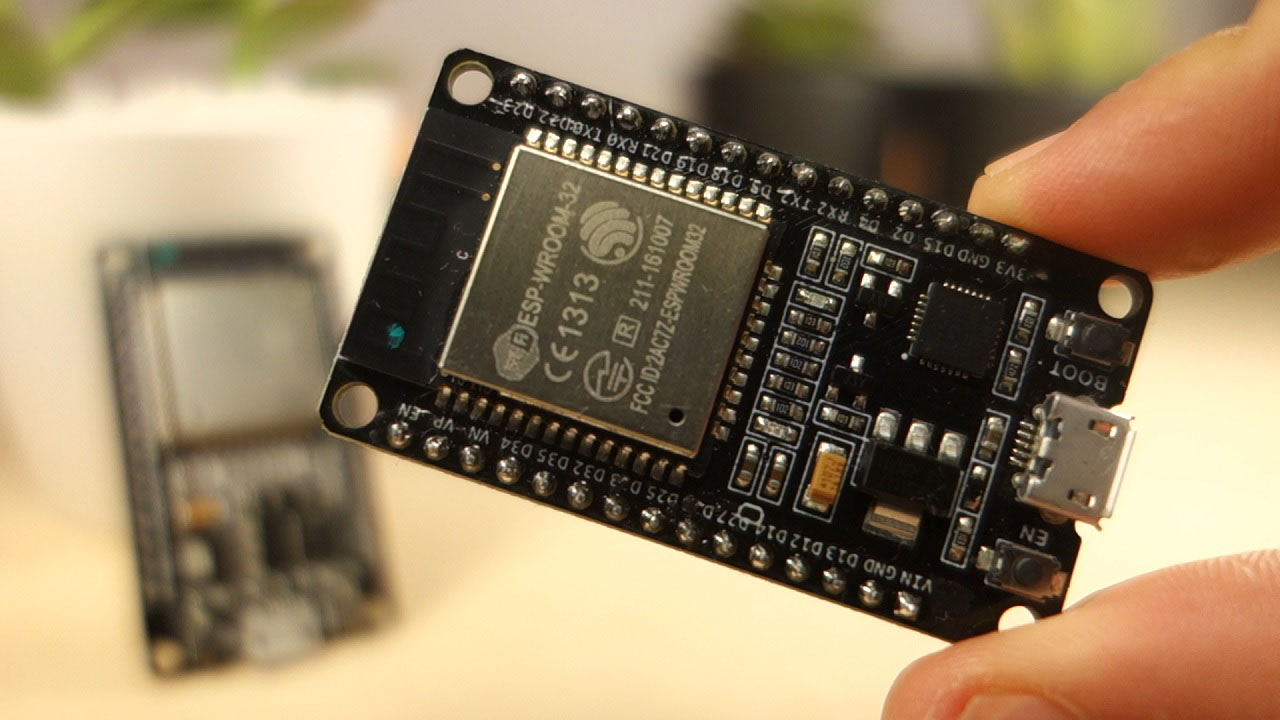
The ESP32 comes with 48 GPIOs with multiple functions. This article intends to be a simple and easy to follow reference guide for the ESP32 GPIOs.
torn frigate
in this case the NodeMCU Mini - ESP8266 (Wi-Fi) module
can display the sensors output, right?
acoustic nebula
ESP8266 has very little exposed I/O, so you will need a different way to connect many analog inputs
acoustic nebula
I don't have that particular board, but if it's an ESP32, it should
north stream
As I pointed out, you could use another chip to read the analog inputs: while a Uno is overkill, it would work.
acoustic nebula
I can't guarantee it since I haven't used that board
torn frigate
looks like it's very cheap($5) so overkill isn't an issue
thanks a lot for the help
north stream
Sometimes availability is more important than engineering minimalism.
eager jewel
NodeMCU (ESP8266) is different than the ESP32 DevKit, which looks similar. I always need to straddle the devkit across 2 breadboards though.
Top is Wemos D1 Mini, next is NodeMCU, bottom is ESP32 DevKit
 sudden fox
Hi there, I'm attempting a project on a NodeMCU 0.9 ESP8266 board using the Adafruit_IO_Arduino library, but I find that simply #include ing the library's headers results in the following error:
/Adafruit_IO_Arduino/src/wifi/AdafruitIO_ESP8266.cpp:22:53: error: cannot allocate an object of abstract type 'HttpClient'
_http = new HttpClient(*_client, _host, _http_port);
From all I can tell reading through the ArduinoHttpClient sources, the error is correctly pointing out that their are unimplemented virtual methods in HttpClient. Any guidance on what I may be doing wrong would be appreciated.
north stream
I tried to replicate it myself, I installed the dependencies in https://adafruit-io-arduino.readthedocs.io/en/latest/dependencies.html then found out I needed more (Ethernet2, and FONA). Now I'm getting "invalid abstract return type for member function 'EthernetClient EthernetServer::available()'
EthernetClient available();"
The error you're seeing might be you need to install or update the Arduino HTTP library?
 winged rose
if i have a dragonboard 410c
do i need a sensor mezzanine to connect it
so it works with my code
north stream
It should work without anything connected. I looked at it, and it appears there's a low-speed 40-pin expansion with GPIO access that you can simply plug things into with ordinary jumper wires if you want, as well as a 60-pin high-speed connector with USP, MIPI, etc. – I'm guessing that's the one that a mezzanine board plugs into.
In other words, for simple GPIO, SPI, I2C type access, you can plug into the Berg style connector.
sudden fox
@north stream Thanks for taking a look at this. The version of ArduinoHttpClient I'm using is 0.3.2 --- the latest coming from https://github.com/arduino-libraries/ArduinoHttpClient
I've also tried some older versions of the http client library to see if it was recent changes that caused this problem, but as far back as a year ago I get the same error.
What board are you working with? And what version of the Arduino IDE? I'm on 1.8.8.
May be time to file a bug report....

GitHub
Arduino HTTP Client library. Contribute to arduino-libraries/ArduinoHttpClient development by creating an account on GitHub.
sudden fox
@north stream Actually looks like it's a known issue, resolved by downgrading the ESP8266 board code to 2.4.2. The issue: https://github.com/adafruit/Adafruit_IO_Arduino/issues/79

GitHub
Arduino board: NodeMCU 1.0 (ESP-12E Module) Board package 2.5.0 Arduino IDE version (found in Arduino -> About Arduino menu): 1.8.8 Open any example sketch switch board to any ESP8266 one compil...
pine bramble
Hi together, i still have a problem reguarding BLE with constant data transfer. A device is supposed to deliver constant data. At 512 Hz shell be transfered 3 voltages from strain gauges together with an acceleration sensor. There should be transfered also a temperature and a batt voltage from time to time.
My idea was to bundle the data to slightly larger packages of 14 data sets with 17 bytes each, starting with a unique number for the complete package (to be able to control if there is data lost), the temp and bat data and inside each of the 14 data sets should be a unique number for the data-set, the 3 voltages from the strain gauges and the 3 accelerometer values and a stop-byte. is this even possible or do i have a wrong idea of what is possible?
I read that BLE is capable of only sending transmissions within at least 7.5ms, but i get within slightly less than 2ms the data of the strain gauges and the accelerometer, so i definitly need to bundle them.
Who may help me with this problem?
and i'm very sorry for my poor english, but i hope i am understandable.
What i was tryint is to set a higher MTU for the UART Service, but somehow i'm totaly failing with it it seems
pine bramble
When we receive sensor data from arduino to pc in serial.begin(9600) how can we know time difference between each sample?
and in general would it be around micro seconds or milli seconds?
assume there is no other code in the system
let say I am taking a voltage and a current reading if i don't know the time stamps of these readings i can't extract information from them
tough snow
@pine bramble You can use millis to grab the milliseconds since the program started. You can use this to check how long it has been since the last check.
I'd go into detail, but it's the end of my lunch break.
pine bramble
ok well more importantly if i have arduino connected to pc can I timestamp whatever sensor reading i get in the serial plotter?
it seems useless to me cause i get only the value
and not the time
for each input
i feel like the PC should be able to know when the arduino sent it a specific variable
 north stream
You could solder header pins to it and plug it into a breadboard. If you don't want to solder it, I suppose you could connect to it with pogo pins.
north stream
I'm fond of these spring-loaded pogo pin clips myself. https://img.alicdn.com/imgextra/i3/139236896/TB2HlWaoXXXXXcwXXXXXXXXXXXX_!!139236896.gif
 crisp talon
I asked this question earlier but I was only told it was doable not how:
my question is with the bluefruit nrf52
how can i use it with the library
#include <Keyboard.h>
or
#include <Mouse.h>
north stream
Which Bluefruit nRF52? The Feather?
crisp talon
the feather
north stream
I don't think it can do that, since the USB interface is a CP2014 chip. I've only seen HID done on chips with native USB support. However, there's a chance someone else knows more about it than I do.
crisp talon
okay then
is there any way a teensy and a adafruit bluefruit nrf52 feather can communicate between each other?
north stream
Yeah, asynchronous serial, I2C, SPI, etc.
north stream
I2C is a fairly low-level protocol, it lets you send and receive bytes to designated addresses. You could design a simple "command" packet format to communicate whatever you're trying to do (for example, you could decide that 0x03 means "listen for data", and the reply would include the data received).
crisp talon
is there a website that would explain this in more detail?
north stream
SparkFun offers a decent writeup https://learn.sparkfun.com/tutorials/i2c/all
crisp talon
thanks
winged rose
so if i just have a dragonboard 410c can i connect it to my host computer
because i looked up guides and they say i need other stuff, like a sensors mezzanine or other stuff
north stream
I think you only need that if you want to program it with the Arduino IDE
honest nimbus
It's possible to software bit-bang USB, but it's not trivial. That said, it's how things like the original Trinket and the Digispark get USB out of an ATTiny85

Objective Development
Discover powerful applications such as Little Snitch, LaunchBar and Micro Snitch.
north stream
If you just want the USB UART that the mezzanine board provides, you could get that with a generic one like https://www.adafruit.com/product/954
inland crag
I just noticed what may be a bug in arduinocore-samd
you're trying to set up a 12MHz clock here, so you divide the DFLL by 4, but you also set divsel which makes it 2*(n+1) = 10

GitHub
Contribute to adafruit/ArduinoCore-samd development by creating an account on GitHub.
at least I'm pretty sure that's what divsel does, the datasheet is confusing here.
inland crag
yeah I just confirmed that running that with divsel on gives you a 1.5MHz clock not a 12 MHz one
inland crag
haha someone else found the same issue 2 hours earlier
 harsh wind
Hi guys, I tried setting Adafruit's Ultimate GPS Module with my arduino nano and I ran their 'parsing' code as a test and I just get alien mumble jumble. I have the wires in the correct pins and my code is just like this one: https://github.com/adafruit/Adafruit_GPS/tree/master/examples/parsing\
if anybody could offer some insight as to why it's doing this, that would be much appreciated!
north kelp
Hey, @harsh wind! I'm looking at that sketch; in setup() it wants 115200 baud for the Serial Monitor. In the Serial Monitor at the bottom right, try changing the baud rate accordingly. It's probably set at 9600 baud.
harsh wind
wow literally 3 clicks away from success 😫
lol thank you though. I spent hours looking at the code and tutorials trying to figure out what i was doing wrong. I'm pretty new to arduino so I forgot about the whole baud rate setting thing. Thanks again!
harsh wind
I'll probably be asking more simple questions like that long before I'm answering them xD
Hey while your here, do you happen to use Microsoft Visual Studio?
north kelp
I just started using MS VS Code, the new hotness.
Are you using traditional VS?
I used Code for the first time 9 days ago at the DevCamp hackathon, making this:
https://twitter.com/erico/status/1092261259544674304


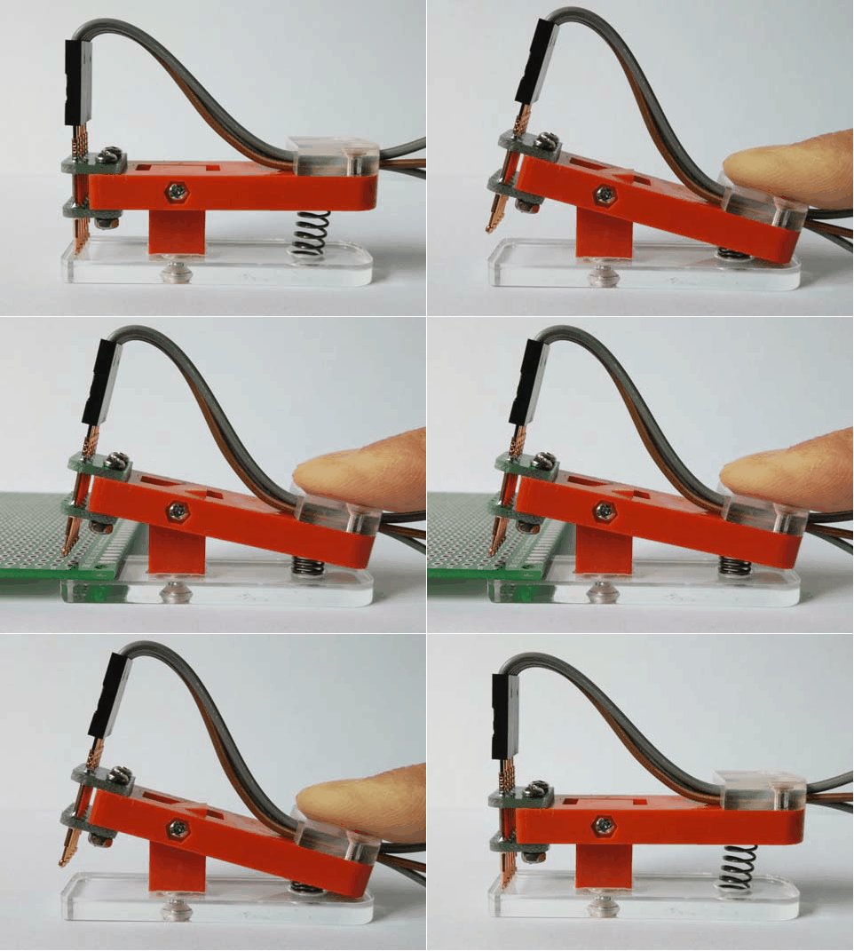
Proud to win #devcamp’s “coolest hack”! @neil_c_heather & I demo #geekyjacket our @flutterio-controlled, blingy wearable.
Flutter controls an @adafruit Feather M0 MCU via Bluetooth LE. NeoPixel LEDs gently diffused w black chiffon (@JoAnn_Stores!)
Thx @dom & @iPhon...
 Twitter
harsh wind
Twitter
harsh wind
not really sure the difference to be honest. I just started using it not even a week ago and I keep getting these "include" errors where the libraries im trying to include are creating an error but I have them in a 'lib' folder that is in the same project folder as the code but it says that i need to fix some "inteliSense" setting to make the path reachable or something but i have no idea how. I read that other people also have this issue but their solutions don't seem to pertain to what my error is.
north kelp
Are you using it for Arduino sketches?
harsh wind
yea but I need to use it because im using this "Particle" IoT development board and I have an extension that flashes the sketches to the board over cellular.
north kelp
Which Particle?
harsh wind
Boron
I was actually trying to run the same code i just showed u on the particle but couldn't get the libraries to work on vscode so I plugged my arduino nano in and put it on there to just test it
north kelp
Do you have a recent version of the Arduino IDE installed? I believe Code looks for Arduino libraries in Arduino's libraries folder. Which is in My Documents\Arduino\libraries on Windows, and ~/Documents/Arduino/libraries on macOS.
That's where I'd install a GPS library for Arduino.
That way it's available to all your Arduino projects, without having to include it in the project itself.
north kelp
Here's Particle's guide for using Arduino libraries:
https://docs.particle.io/tutorials/device-os/libraries/
harsh wind
so particle has an old IDE that i originally used that looks for code in the 'particle' document but vscode might have like you said been looking in arduino folders and such
do you work with particle boards as well?
north kelp
No, not yet.
harsh wind
I like to pretend that I do xD
north kelp
I'm super pretending by trying to help. 😃
harsh wind
Well you have been more helpful than my own brain has so obviously you are better at pretending xD
north kelp
Sometimes just a second pair of eyes is useful.
harsh wind
please bear with all the questions. I just turned 16 and have only worked with Python and RPi
north kelp
No worries.
harsh wind
thats my excuse for the baud rate question lol
north kelp
😃
harsh wind
so I put the code in the arduino folder but it still isn't finding the libraries even though the Arduino IDE found them in the same format. Is there something else I have to do?
north kelp
Working with the Arduino Nano, or the Particle Boron?
And this is with VS Code, right?
harsh wind
Boron and VSCode
north kelp
If you choose "About…" in VS, what is the name and version of the MS VS product?
north kelp
Very well could be paths.
harsh wind
i feel like the files aren't in the right folder or the path finder in VScode isnt set to look for the right folder
python was so easy. pip install this and that then just import it but now i gotta use github and its a pain
north kelp
It also might be that the particular library isn't one of the 3000 libraries that Particle has public support for, in which case you'd need to probably upload it as a private library.
harsh wind
well like even without anything particle the compiler still tells me that I'm doing something wrong
north kelp
Is there a simple blink sketch you can upload to the Boron from VS Code?
harsh wind
yea let me give that a go
north kelp
Then I'd definitely surf around:

Particle
Discourse about Particle devices, the Particle cloud, and all things related to connected devices in the IoT era.
harsh wind
I think i have done that before and it has worked except reception here is kind of spotty so it sometimes takes a while for it to find a connection
alright thanks for your time and help! i really appreciate it! It's a school night for me so this is a project that will have to be resumed tomorrow! have a good night!
north kelp
You've probably run through this, but here it is anyway:
https://docs.particle.io/quickstart/boron/
Alright, I gotta get back to work. Good chatting!
 zinc barn
How difficult would it be to use a NeoTrellis M4 and make it wired instead of wireless for this guide? https://learn.adafruit.com/neotrellis-neopixel-controller

A Reliable Radio Control Box for All the Lights in Your Life
nimble terrace
hey, is wemos d1 mini format outdated nowdays ? I m making my first steps here using a D1 ESP32 and I like it. I wonder if I should stay with this serie and get some more ESP and shields ? Or if there is a better option today ? My main use case is
learning and indoor sensor monitoring + automation. Thx
wide lark
hey @nimble terrace this is just my opinion but as long as it works for your use case then I'd say it's an "in-date" platform for you 😃 I use ESP-type boards (ESP8266 & ESP32s) all the time myself, they do what I need. but heck, I still use a first-generation iPad mini because it works fine for what I need, so I may not be the best person to ask 😃
@nimble terrace practically speaking though, I'd suggest that as long as a board family is still actively supported by the community (most definitely true for the ESP family) then it's still quite relevant
nimble terrace
ok, thx. this family look supported, featured and cheap. I wonder why it stopped.
wide lark
and really when you think about it, the ESP boards tend to have quite a good size chunk of RAM, making then very desirable (get that CircuitPython on there! :))
yeah who knows, generally can be a lot of other factors than just technological ones for a line to stop
nimble terrace
I m too new to use Ram by myself 😃
wide lark
and like you said, boy are they cheap! I can find ESP8266 board from China for $3!!
@nimble terrace haha totally fair, just something to be excited about for the future then! and if anything, it just enables you to grow without running into limits of the device too early
nimble terrace
I focus on esp32, but ya 8266 is even cheaper
wide lark
@nimble terrace yup yup, both fantastic choices, generally the 8266 is chosen when you want to reduce cost and know you can still function with the reduced resources, so starting with the 32s instead is a good call (more headroom)
I do admit I bias towards the little things though, they're one of my favorite embedded platforms of all time. so useful for so little outlay! Anyway, I really hope you enjoy working with them, they're a joy. best of luck! (have to get ready for my day now 😃 )
nimble terrace
Yes first step in this world are pleasant, so many possibilites..
have a good day
and thx for your advices
wide lark
you too, and you're more than welcome! ttyl
north stream
@zinc barn The communication format is pretty simple, just packets that are a byte array, it should be possible to swap out the radio code for some sort of wired code. Which type of wiring you'd use depends on the distance you need to go, but probably ordinary RS-232 might do.
acoustic nebula
Question about the nRF52840 Feather. The SPI speed seems to be limited to 6Mhz. Trying to set it higher, it doesn't go any faster. This chip is supposed to support speeds up to 32Mhz. Any ideas why it's not working?
north stream
Could be a bug, or perhaps it's capped in the library for some reason?
acoustic nebula
I'll check the library code - seems like a software issue
north stream
That's where I'd look first.