#help-with-robotics
1 messages · Page 7 of 1
 primal shell
 ashen mural
Hey folks, how hard is it to turn the DC Motor with the encoder? I have a project where the motor needs to spin fairly freely when not being powered (like a Stepper) but keep encoding turns so we can see how far it has moved.
Here's the part in question: https://www.adafruit.com/product/4416
The first step in a robotics project is to get a motor spinning. Once you've done that you quickly learn that not all motors go the same speed, even if they are the same part number! ...
If it's not easy to turn (and I suspect it isn't) - is there a way to add that kind of encoder to a stepper?
primal shell
The encoder doesn't have much effect on the resistance to rotation but the 1:20 gearing does
You can add an encoder to a stepper but it isn't usually done since the stepper already moves a known amount
ashen mural
Yes, but in this case, I need to track when the wheel turns from outside motion
It's for an automated door - which can be moved manually
But we need to track where it is located
primal shell
That makes sense. Stepper are a little difficult to turn (cogging) but an encoder can be added. The usual types are optical, magnetic, or resistive. You'll also want to decide whether you want a relative or absolute one
 tribal magnet
@primal shell I had to spend some time digesting decouplers again in general, so is the rule of thumb to start off first with power line then moving onto to signal?
I'm gleaned quite a number of articles and they are suggesting a combination of both 10uf and 0.1pf capacitors to filter out both low and high frequency noise
I'm also starting to wonder if I need to decouplers to the power line of my mega for instance, or before the stepper driver
I've got got some ferrite beads from an old project and I'm reading that they can be either inductive decouplers (<100mhz) or resistive decouplers too?
primal shell
I generally try to decouple at the source of the noise first. I would probably try to separate the power supplies as well. Since the Mega draws less power, I'd add any series decoupling on that side
tribal magnet
just to get a good idea, the series decoupling is mainly to keep the propogation of the noise to other parts of my system? While I can separate power supplies, I'm trying to work with a one power supply system.
primal shell
I figured, which is why I mentioned series decoupling
 urban wren
@spare patrol and @clear mantle I talked to PT and he told me what they want from the Sphero project. Very very different from what I thought (but arguably cooler). I'm going to write up a one-pager spec and I'll share it with you both in DM as editors.
 spare patrol
Sounds good. Thanks
 brazen tangle
I need advice about the degree of difficulty of a project: How difficult is it to build a wheeled robot with wireless control? There is also a camera put on top of it.
I have some experience with Arduino/Arm/PCB design but sadly no motor control or 3d printing. I'd be happy to know your estimates.
Similar to this explorer bot (from Arduino Robots book):
[John-David_Warren,_Josh_Adams,_Harald_Molle]
 lean quartz
@brazen tangle I'd probablly start with a kit before I got too fancy. https://www.adafruit.com/product/3216 has the motors, wheels, and body. That page also has suggestions on the drivers and controllers you'd need (FeatherWing + Feather, Shield + Arduino, Hat + Pi). Once you've got the basic robot down, then you add some form of wireless and the camera (weight permitting).
Unleash your inner Mad Max and make your vehicle dreams a reality with the Mini Red Round Robot Chassis Kit.This kit gives you everything you need to build the shell of a 2-wheel-drive ...
Or if you find that you want to build full-scale with the rubber wheels and all, the smaller kit would be a good way to get enough experience for cheap. No reason to (and several reasons against) jump straight to the larger chassis with 3d printing and whatever else you might imagine.
tribal magnet
@brazen tangle We built a little fun circuit with a LN298N and just a wemos d1_mini with wifi web control, where kids used a web browser on a handphone to control their own little 'buggy' instances. On the very baseline, you just need a motor driver, 4 wheels, axles and a radio/wifi enabled microcontroller. The camera though, would be an issue, because relaying images is resource intensive with these 8 bit microcontrollers (assuming that is what you want to do). That you would need to get into RTOS-based microcontrollers like raspberry pis.
 real patrol
does anyone have a good explanations/tutorials/courses/books/videos on VSLAM that doesn't assume a phd? Or even just normal slam with a lidar, I'm not picky.
I've tried and tried to find a decent write up but they all seem to be math-centric instead of programming centric.
brazen tangle
How to "throw" something to 20~50 meters with non-lethal speed? I'm not a MechE so I don't even know what keyword to search for
I guess it could be done with 1- Gunpowder, 2- Air Pumps and 3- Springs...Gunpowder is dangerous so that is not an option. Air pumps are heavy and expensive...Can I like attach a spring to the end of a cylindrical tube, and call it a day?
Is this the keyword I should be looking for? "Spring-loaded Launcher" ?
brazen tangle
Based on my rusty calcs. : for m = 0.5 kg, k = 1250, length = 0.1m, velocity would be 5m/s...Then distance traveled for theta = 0 and y0 = 1 would be 2.25 meters 😦
primal shell
By re-arranging the equations, you can calculate the launch velocity for a parabola with a width of 50 meters (hint: theta will be 45°).
brazen tangle
@primal shell My more important question is, can I use a spring-launcher to throw a 500g device horizontally 10~20 meters?
primal shell
Sure you can. As you already described, you just need to know the launch track length and can derive the required spring K factor.
(more accurately, solve for the required acceleration, then for K)
brazen tangle
@primal shell You see most examples on the net are for 10g objects (like pencils, tennis balls)
I'm wondering if 10~20 meters requires air compressed pumps or some chemicals
primal shell
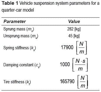
No, it can be done with a spring (or elastic, or magnetic acceleration, or whatever), you'll just need a beefier spring. (if it ends up being the kind of springs used in automobile suspension, you're going to have to build a pretty large and heavy robot or change some parameters)
The weight of the object is just another parameter in the equation, and fortunately, this is in the linear regime, so to scale up from 10g to 500g, you can just multiply the forces required by 50 (because F = MA).
brazen tangle
@primal shell So how can I check which springs are readily available? For example is a spring with K = 12500, for a car suspension? Is it difficult to make/buy?
velocity(K = 12500, l = 0.1, m = 0.5) => 15m/s
distance(v = 15, theta = 5,y0 = 1) => 9 meters
primal shell
Choose from our selection of springs, including over 7000 products in a wide range of styles and sizes. In stock and ready to ship.
If you drill down into spring catalogs, you'll find them listed in various ways. McMaster-Carr lists them by "rate" in pounds per inch.
Looks like one choice (confined-space conical compression springs) offers rates from 1.61 pounds per inch to 59.45.
brazen tangle
@primal shell So 59.45 would be 10680 N/m
@primal shell Can I actually make the spring myself?
confined type was a good idea 😄
primal shell
Yes, you can. However, it's easier to make torsion springs and elastic mechanisms yourself than coil springs.
brazen tangle
@primal shell Are you MechEng?
primal shell
Nope. I'm a tinkerer with an appetite for books.
Under "die spring stock", they have some 103.58 rate 1-13/16 coil stock in 36" lengths, for $118.15
brazen tangle

According to this, car spring's K is on this order (12500 N/m)...
I guess that is a bad thing for me
primal shell
Yeah, those are some largish forces. I'm guessing the large forces are coming from a too-short acceleration distance and can be relaxed by increasing the length of the launch
I tend to do these calculations in gravities, so to accelerate something to 1m/s in 1m takes about 0.1g. To accelerate something to the same speed in 10cm takes about 10g. One advantage to the "acceleration" approach is it's independent of mass.
Just watch out for confusing g=grams for g=gravities of acceleration
Once you've worked out the acceleration you need, you multiply it by the mass of the object to get the force required.
brazen tangle
@primal shell thanks
primal shell
I'm hoping I was actually helpful
urban wren
Trebouchet. Or rail gun.
brazen tangle
@urban wren can a hand-made rail gun throw a 500g device to 10~20 meters?
How much current is needed? Isn't building it dangerous because of high currents involved?
brazen tangle
Also it seems the projectile itself should be metallic...The current should pass through it and it may damage my device
urban wren
@brazen tangle Up until very recently (as my limited knowlege indicates was around 2015) all railguns were hand made. The performance of different implementations varies pretty wildly, but a properly designed railgun of about 7 meters length throwing only 500g should be able to achieve a muzzle velocity of about 11,100 ft/s, or 7,600 mph. I'm pretty sure that'll go 10 to 20 meters. 😉 The projectile doesn't have to be metallic, since the drive armature actually creates the acceleration (kind of like a sabot). You correctly point out that current is dangerous. The above numbers assumed 4.5 megaamps (yes, 4.5 million amps). This is somewhat dangerous and difficult to transfer to the gun itself because all that energy needs to be dumped into the gun in about 8 milliseconds.
That said, I was kind of joking when I said rail gun, but you could probably acheive what you need with a vacuum cannon.
Also, be sure to video the railgun if you build one. The plasma from the projectile at those velocities is, I hear, pretty spectacular.
brazen tangle
@urban wren 7 meters is too long. Also the speed is dangerous. How about vacuum cannon? Is there a DIY compact kit that I could use? What would be the size/dimensions of the launcher?
urban wren
@brazen tangle I don't know of a kit. It's basically a PVC pipe, maybe a meter long, with a valve at the breech. You hook the valve to a compressed gas cylinder, tape over the muzzle, pump all the air out of the barrel, and then open the valve. Results can be pretty spectacular.
Here's a video that could give you some good ideas (and they'll cost less than several million dollars): https://youtu.be/JT0wx27J9xs

Make an awesome website today at: https://wix.com/go/Smarter
Check out my Wix website here: http://www.subscribetomarkrober.com
Click here if you're interested in subscribing: http://bit.ly/Subscribe2SED
⇊ Click below for more links! ⇊
GET ...Trebuchet should be feasible, at least. Maybe a very long-extension slingshot type thing, too. Either should be relatively safe compared to anything involving PVC and compressed air. https://www.instructables.com/id/How-to-Build-an-Awesome-Trebuchet/ shows a baseball-launching trebuchet that went 240 feet (73 m), and a baseball is 150 g versus your 500 g requirement.

Instructables
How to Build an Awesome Trebuchet: Do you enjoy building? Do you like huge projectile machine? If this sounds like you, we have a project to satisfy all your cravings. Trebuchets will make any day of the week so much better. In this Instructable we will teach you how to build...
I have seen working basketball-launching trebuchets of about that size and weight, but I don't recall their range. Basketball is a bit over 600 g.
urban wren
I like vacuum cannons. 🙂 I also, however, like catapults. A lot. Held the world record for powered-arm catapult throw for a while. Stil might. I haven't followed it since '83.
 sly sand
I had a new (for me) adaptation of treb geometry the other day (repurposing it for some other use case - not send projectiles but to apply static force, iirc)
 viral pagoda
Hey guys, I have a project that uses a CR2 battery buried away in the housing and was curious if there is a way that I can connect it to something (circuit or device) from the outside to monitor the battery level. Would like to be able to periodically check the battery status without having to take everything apart to get at the battery before replacement. Any suggestions would be greatly appreciated!
 candid stirrup
I'm playing around with a line follower robot (actually a sumobot, so a reverse line follower) I made. Now, I was using a fairly simple mounting of a couple of TCRT 5000 IR sensor modules on the front on the left and right. They work fine, but I definitely am seeing a lot of noise. If I was just straight up using the IR receiver / transmitter, I'd sample it off and then sample it on and use that to calibrate. However, the module adds a LM393, a trim pot, and pins for voltage, gnd, digital and analog outs. I can't individually control the transmit / receive LEDs. Any suggestions as to how to deal with noise or calibrate? I was thinking pre-competition I'd have a button on the bot that when pressed would take a sample on the black. Second press would be a sample on the white. But, I'm worried that will be seen as weird during the competition. Any ideas or suggestions?
primal shell
There are lots of way to filter noise, both electronically and in software. It's also possible to do dynamic threshold detection to detect lines/edges in different conditionss (again, both electronically and in software).
candid stirrup
Such as?
Because I've been hammering at this problem for a few weeks and the only ideas I've had are to use a different (more expensive) sensor or the aforementioned calibrate pre-competition (which is probably a no-go). I'd really like to stick with the cheap sensors as I'm trying to build a bunch of these bots with kids and spending lots of $$ isn't in the cards.
@viral pagoda Does something like this help (I'm assuming there's a microcontroller in your project somewhere): https://jeelabs.org/2013/05/15/what-if-we-want-to-know-the-battery-state/
 carmine nimbus
@viral pagoda the above would be one solution
viral pagoda
@candid stirrup There actually isn't a microcontroller in my project lol! It is a very simple one so was hoping there would be a simple chip or something I can hook up to the battery that would have a display of the power reading. That is what I'm looking for. Also to clarify, I'm using a CR2 battery that I'm trying to monitor the life on.
carmine nimbus

eBay
Find many great new & used options and get the best deals for 0.28'' 0.36'' Mini DC 0-99.9V LED Display 2/3Wire Panel Voltmeter Voltage Meter at the best online prices at eBay! Free shipping for many products!
primal shell
You might be able to filter it with a simple capacitor (or resistor-capacitor) filter on the signal lead to keep it from making too-rapid transitions. Adaptive threshold is a little more complicated, basically you use a largish capacitor to keep track of the current prevailing average level, then a comparator and some resistors to detect when the signal changes by a particular amount from the recent average.
candid stirrup
Hmm...I'm going to have to think on it more. I'm really trying to minimize the amount of parts these bots use, but there's nothing worse than setting your bot in the ring and having it immediately roll out because it thinks everything is black. When we're building them, adjusting the pot really gives the kids a sense of control (I output the analog and digital values to the serial monitor and let them adjust the pot) but doing it every time you want to compete gets annoying fast.
primal shell
Sounds like a variable threshold works, but it's manual now. Perhaps a light on the underside to minimize brightness variations?
 worn loom
hey Adafruit... anyone has experience working with TOF sensors?
is it normal for them to fluctuate +-3mm?
I'm testing the VL53L0X and VL6180X
Both seem to fluctuate around 3mm
 lone skiff
That seems to be in spec, as those only advertise about a 3-10% accuracy depending on range and reflectivity.
primal shell
Let's see, the speed of light is 299,000,000 meters per second, and you're seeing .003 meter fluctuation. That's what, about 20 picoseconds, accounting for round-trip? That's AMAZING for an affordable sensor people can buy.
 bronze flower
Need help with stepper motors. Planning to build a simple rig that draws the curtains. Which kind of stepper motor would be able to do the job? I’ve used smaller stepper motors before good for panning small cameras. Im sure those wont cut it
 heady spire
Hello,
I'm having problems with pigpio. I'm using a Pololu 18v18 HAT on a RPi 3B+. When I try to run my Python script (As root or as pi), I get this:
%%%%%%%%%%%%%%%%%%%%%%%%%%%%%%%%%%%%%%%%%%%%%%%%%%%%%%%%%%%%
Can't connect to pigpio at localhost(8888)
Did you start the pigpio daemon? E.g. sudo pigpiod
Did you specify the correct Pi host/port in the environment
variables PIGPIO_ADDR/PIGPIO_PORT?
E.g. export PIGPIO_ADDR=soft, export PIGPIO_PORT=8888
Did you specify the correct Pi host/port in the
pigpio.pi() function? E.g. pigpio.pi('soft', 8888)
%%%%%%%%%%%%%%%%%%%%%%%%%%%%%%%%%%%%%%%%%%%%%%%%%%%%%%%%%%%%
Traceback (most recent call last):
File "example2.py", line 4, in <module>
from dual_g2_hpmd_rpi import motors, MAX_SPEED
File "/usr/local/lib/python3.7/dist-packages/dual_g2_hpmd_rpi.py", line 5, in <module>
raise IOError("Can't connect to pigpio")
OSError: Can't connect to pigpio
I've tried sudo pigpiod, but it returns this:
2020-01-11 16:30:22 initPeripherals: mmap gpio failed (Operation not permitted)
Can't initialise pigpio library
I've also tried using sudo systemctl start pigpiod, which returns no errors, but it still doesn't work. When I did sudo systemctl status pigpiod, and it says:
● pigpiod.service - Daemon required to control GPIO pins via pigpio
Loaded: loaded (/lib/systemd/system/pigpiod.service; enabled; vendor preset: enabled)
Active: failed (Result: exit-code) since Sat 2020-01-11 16:34:56 EST; 1s ago
Process: 3782 ExecStart=/usr/bin/pigpiod -l (code=exited, status=0/SUCCESS)
Main PID: 3783 (code=exited, status=1/FAILURE)
Jan 11 16:34:56 Stida systemd[1]: Starting Daemon required to control GPIO pins via pigpio...
Jan 11 16:34:56 Stida pigpiod[3782]: 2020-01-11 16:34:56 initPeripherals: mmap gpio failed (Operation not permitted)
Jan 11 16:34:56 Stida pigpiod[3782]: Can't initialise pigpio library
Jan 11 16:34:56 Stida systemd[1]: Started Daemon required to control GPIO pins via pigpio.
Jan 11 16:34:56 Stida systemd[1]: pigpiod.service: Main process exited, code=exited, status=1/FAILURE
Jan 11 16:34:56 Stida systemd[1]: pigpiod.service: Failed with result 'exit-code'.
I've also tried reinstalling it with sudo apt-get install --reinstall python-pigpio* python3-pigpio* pigpio* -y
Any ideas?
primal shell
It looks like initPeripherals: mmap gpio failed (Operation not permitted) is your base error. For some reason it's unable to memory map gpio. I wonder if it's trying to re-use a pin that something else is already using or somesuch.
 left coral
Looks like there's some discussion here: https://github.com/joan2937/pigpio/issues/259
GitHub
Hi, I know this issue has already been talked about, but I got the following issue: running sudo pigpiod returns: initPeripherals: mmap gpio failed (Operation not permitted) Can't initialis...
 sharp lark
@bronze flower have you considered using regular dc motors with a gearbox and touch sensors?
Might be easier than trying to get a stepper with enough torque to draw some curtains
Depends how heavy they are tho
primal shell
Theoretically you could use a geared stepper for more torque, but that slows everything down, and steppers can't turn very fast.
bronze flower
I am actually considering using dc motors with an end stop as suggested by a few people here on the channel. I preferred the stepper motor because it was easier for me to control the amount of rotations using software. But it’s starting to look like the dc motor is a better solution because of torque and speed. I will need to find a clever way to trigger the end stop on both directions though
Also another consideration was with a stepper motor there would be no way to allow manual opening/closing of the curtains. With a dc motor you can do that with no problem
 dry prawn
you can, and should, disable the stepper drivers after you're done moving otherwise the motors will just get hot for no reason. With the drivers off the motors will spin free
 karmic heron
Does anyone know why a 28byj converted to bipolar and powered using 12v and a a4988 would be very weak (weaker than when it was unipolar) and when i put load on it, it wants to switch direction.
Im using about 0.15vref so 0.3 amps?
Im fullstepping and tried different pulsewidths and step delays.
Its a 5v version, so im using 12v now
heady spire
Hello again,
I looked at https://github.com/joan2937/pigpio/issues/259, and I'm honestly confused. I know what a kernel is, but I don't understand the fix. Is there a one-liner to fix the problem?
GitHub
pigpio is a C library for the Raspberry which allows control of the General Purpose Input Outputs (GPIO). - joan2937/pigpio
primal shell
@karmic heron, If it was a 5-wire stepper, probably cross-leakage. If it was a 6-wire stepper, might have chosen the wrong wires?
karmic heron
@primal shell no connection between coils if i measure. Im sure I cut the tap on both coils
primal shell
I'll admit, I'm not sure what you really did here.
karmic heron
@madbodger found it. One of the coils has a break in it, so once it gets warm. It disconnecta. And only one coil drives the stepper
primal shell
That'll make it weak and ineffective. 😦
 terse pike
For the metal gear on servos like the 2307, what is the pitch of the teeth? Looking for compatible differential/pinion gears, thanks!
primal shell
These should fit https://www.servocity.com/32p-25t-3f-spline-servo-mount-gears
Finally a way to drive gears using servos! Our patented 32 pitch Futaba metal gears are designed to attach directly to the output spline of a servo. All gears are broached directly into the metal to ensure a snug fit that will not slip. These gears are
terse pike
It looks like those might have 25 splines on the inside connection while the 2307 has 20? https://www.sparkfun.com/products/12184

These servo gears are made specifically to fit a Futaba 3F servo spline, allowing you to mate other gears to your servo. They have 20 teeth with a gear pit
primal shell
I think the outside of the gear has 20 teeth, but I suspect the hub has 25 splines. What I don't know is their pitch. I suppose it would be possible to measure the diameter and do some math to work it out.
terse pike
awesome, will look into. is the maximum power draw @ 5v known for the 2307/mg92b? i've checked towerpro but haven't found anything
primal shell
terse pike
haha of course. thanks!
 dawn mulch
@terse pike For what its worth, I find it odd that the Towerpro MG92B output shaft has 20 splines. There are very few servos with that number of splines and I cannot find any servo gears that will attach to a servo with an output shaft with 20 splines. Most servos have 24 or 25 splines. ServoCity has a good Spline Info page Link 1
I would highly recommend the Hitec mini or micro servos link2 they are well built and have 24 splines on the output shaft. ServoCity also carries many gears (I prefer the 32 pitch gears, not as quiet as 42 pitch gears but stronger and more forgiving when it comes to alignment) link 3 and sprockets Link that attach directly to the servo or can be attached with special servo hubs Link 4. I have used many products from ServoCity and have always been very satisfied with the quality and customer service.
Hope this helps. Have fun with your robot build.
Sorry, for some reason the URLs did not come thru, here they are:
https://www.servocity.com/servo-spline-info
https://www.servocity.com/servos/hitec-servos
https://www.servocity.com/motion-components/rotary-motion/gears/servo-mount-gears
https://www.servocity.com/servos/servo-accessories/servo-attachments/hubs
 remote cedar
I have a brushless motor. It has the wires for all 3 phases plus 5 wires for hall effect sensors:
W, V, U, GND, HW, HV, HU, H5V
The original controller I got with the motor is no longer working. If I could just replace the controller with an RC brushless controller that'd be fine with me. But none of those have inputs for hall effect sensors.
Do I need the hall sensor signals in order to use the motor? Or will it still work fine if I omit them and just use an RC controller?
I don't have a brushless RC controller on hand to test and try it out
primal shell
It works better at low RPM with the hall effect sensors, but will still operate just using the phase leads.
primal shell
The hall sensors let the controller monitor the rotor phase accurately. Without that information, the controller has to derive the rotor position from the back EMF of the undriven winding in a thicket of electrical noise. Additionally, there's no back EMF if the motor isn't turning, so when it's stopped, the controller has no way of knowing its position without the additional sensors.
remote cedar
that makes sense
Thanks. I guess I should probably look to pickup a controller with hall sensor inputs then
primal shell
They're not as popular, and therefore a little harder to find, but they're out there. My tractor uses a quartet of them.
remote cedar
Yeah this is what I've noticed. I was looking around amazon. There are some, but they're 3rd party sellers from China. I'd rather get them from within Canada if I could for time constraint reasons.
primal shell
Good idea.
remote cedar
I'll keep looking. Thanks for the help.
Those "hoverboards" seem like the most common application for the style of BLDC controller I'm looking for. Which is likely why there's a bunch of these controllers available in China haha.
primal shell
Here's one example controller not out of China. Don't know if it's appropriate to your voltage/current/RPM/torque/power, but they're out there. https://www.anaheimautomation.com/products/brushless/brushless-driver-controller-item.php
primal shell
That one says "open loop", which I think means it doesn't support Hall sensors
Nope, I'm wrong: the wiring diagram shows sensor inputs. I think that one will work for you. Not sure if there's a Canadian reseller, but hopefully there is.
 fierce belfry
In general speaking, what gives better movement accuracy. A stepper motor or A stepper motor with a planetary gear box ? and lets assume both motors and same and gear box multiplies the torque by 3 and is there any benefit of using gearbox steppers in a Delta Robot
or should I buy a stepper and look to attach an encoder with it
for that very purpose
primal shell
The stepper is pretty accurate on its own. A gearbox will multiply torque and reduce speed, but will generally add inaccuracy due to backlash. However, it will add precision (by multiplying the number of steps per revolution). The concept of reducing accuracy while increasing precision is a confusing one, but that's the case here. An encoder generally won't help any, that's more for use for either a less precise motor (like a DC motor) or for detecting absolute position or missing steps.
primal shell
That depends on your use case and parameters. Many designs run "open loop", just sending pulses to steppers and assuming that everything works. However, you can move to closed loop with sensors/encoders to get more assurance that things are moving the way you intend.
 agile socket
I'm having some trouble running stepper motors off of the RPi bonnet (https://www.adafruit.com/product/4280) anyone here who can lend an ear?
I'm getting really jerky motion from my steppers, and I noticed that the power indicator was flashing. Power supply is giving me 12.23v and 4.xxA, but I haven't been able to get a solid read.
This is the code I've been running
primal shell
Sounds like a power problem. Perhaps a poor connection or too-thin wires. How is it hooked up?
agile socket
I was chatting with a mod about that last night on the circuit python chat. Found I had too much amperage going to the motors. I added a dummy load and it functions better. I'm running it off of wall power currently to write the code, but I'll eventually power it off of 4 18650 lipo batteries, 2 batteries in series paralelled by another 2 in series, for each of 2 boards. That should drop the current so I don't need the dummy load. After that is just fine tuning any dummy load that I might need.
The wire harness that came with the motors, that I'm borrowing from my university, are 26g. I'm not entirely sure if I can install thicker gauge wire into the plastic ports. They're rated for 12v, so I presume they'll function ok.
primal shell
Increasing the impedance of your power supply will reduce the current, but it will also reduce your motor torque. This may or may not become an issue.
26ga is fairly thin for much current at all (wire gauge determines current capacity and loss, wire insulation determine voltage capability)
agile socket
I had the dummy load in parallel with the board I was powering, I didnt think that would drop the voltage? It's been a while since I've done any circuit math.
The board is rated to deliver 1.3A per motor
primal shell
That depends on a lot of things, in particular the impedance and regulation compliance of your power supply.
If your problem is really "too much current to the motors", the logical place to adjust that is on your motor driver board (if it supports motor current regulation: many boards do, but not all)
 true condor
@agile socket This table associates wire guage with ampacity, for both solid and stranded wire. It also notes that insulation type, enclosure, and ambient temperature all factor in. @primal shell likely has an even better resource at his fingertips.
https://www.engineeringtoolbox.com/wire-gauges-d_419.html
Common US AWG wire gauges and amps ratings
 slow spoke
Hello everyone! I need some help with motor selection. I am trying to build a wind turbine! I am interested in a motor that is able to produce the most electricity with the smallest amount of wind applying torque on the fan blades.
Should I be looking into a low RPM or high RPM motor with high torque?
 distant light
What size wire would you guess is in the 5v side of the 5v 10a Adafruit power supply if I took off the black outside cover?
primal shell
It should be printed on the outside of the cable. In the product photos, it appears to be 16AWG, but it's small print at an angle that's tricky to read.
For what it's worth
distant light
Thank you!!!
fierce belfry
uhm I feel this should be fairlly basic but like
anyone with some knowledge of toggle switches
its so simple working things and yet I'm so confused
cant a 3 pin toggle switch working with arduino
like flip the switch and led on
flip it back and led off
isnt this how they work
so if I read the middle pin
and have right one connected to a pin with HIGH
and left one connected to a pin with LOW
so like if I flip it right
the mid pin should read HIGH
and if I flip it left
the mid pin should read LOW
m i missing something here
lone skiff
Yep, that sounds correct if you want to use it as an input like that. Are you seeing different behavior?
fierce belfry
it aint working
like stays constant
im going to shop to buy some new switches
different different types
just this simple thing bothered me so much
lone skiff
Could just be broken. You could test it with a multimeter.
sly sand
The switches are 1:1 corresponding with what's inside and what's outside. There's no reason to route the external contacts differently.
So the middle contact is the common contact.
Genrally you can presuppose a 3-terminal switch is going to turn out to be SPDT (single pole, double throw).
It may or may not have a 'center off' configuration (where in the middle of three positions of the handle, the common contact completes neither circuit).
dawn mulch
@fierce belfry here is an Adafruit tutorial on switches, hope it helps
https://learn.adafruit.com/make-it-switch?view=all

Adafruit Learning System
When your microcontroller needs to accurately read if a switch is flipped
 thorny matrix
Hey guys, I'm trying to make a robot with the Adafruit MotorshieldV2. Does anyone know if the .begin has to be in the void(setup)? I am trying to get functions with .h files and tabs to make programming easier and all of my other components work except for the motors. Even though I set up and called a function that executes .begin (ex. AFMS.begin();) before I do anything, when I call the function to move the motors, nothing happens. It's definitely my programming because the example code works fine.
primal shell
Which library? I don't see a .begin() method in https://github.com/adafruit/Adafruit-Motor-Shield-library
thorny matrix
You’re looking at the v1 board’s library, the v2 switched to i2c which needs the . Begin code

Adafruit Learning System
Stackable, high current DC and Stepper motor shield
primal shell
It looks like .begin() doesn't do anything particularly special https://github.com/adafruit/Adafruit_Motor_Shield_V2_Library/blob/master/Adafruit_MotorShield.cpp#L68 but perhaps you have some other peripheral that's adjusting I2C bus settings?
 grim kayak
Hi guys, Im working on a robot with two wheels and there's one problem I haven't figured out - with the first prototype I used low end DC motors with a l293d motor shield. When I attempted to push both motors at the same speed, the robot would end up turning to an angle and eventually go out of the testing bounds - I fixed this issue by putting the robot between a tightrope. If I used a high quality stepper motor, would it be precise enough to go straight or would I still need to figure out a way to keep it straight? I have to mitigate as much friction and delay as possible so a tightrope would be quite costly in that sense
And if anything would à stepper motor or à servo be the best tool for the job
primal shell
A stepper (or DC motor with an encoder and a feedback loop) would help, but you could still have differential friction/traction issues. The tightrope approach is simple and effective. To do it electronically, you'd probably want a gyroscope, magnetometer, or sensor-based (line following, beacon orientation, or visual reckoning).
grim kayak
Hmm, I'll go ahead and try the stepper
Thanks!
If anything I'll try to correct its posture with a small retracting "leash" that serves as a power cable
 merry cargo
Has anyone ever used micro steppers (not particularly these on the picture it's just here for reference) for making a robot? These are mostly used in camera's or phones, but they might not be powerfull enough to push a leg or an arm (3D printed).
primal shell
I have some steppers like that, but haven't played with them yet. With a leadscrew, they might be able to push a leg or arm, albeit slowly.
karmic heron
Hello! Does anyone know if there is a stepper close to the 28BYJ-48, but with metal gears.. i think im into my 4th stepper with a broken gearbox after a couple of hours running
would love if its the same formfactor, but im guessin there isnt.. most off my projects are designed around the 28byj
primal shell
That's a cheap twee little thing designed to move air conditioner louvers periodically. Not for anything demanding or continuous duty. Depending on your project, there are more robust motors out there, which one would suit you depends on your parameters. The toughest one is drive: the little 28BYJ runs fine on 5V and low current: not many steppers do.
karmic heron
i have a A4988 to work with, running the 28byj on 12V and Bipolarmodded, most important for me is formfactor, since almost all my projects have been using teh 28byj
i wonder if there is a metal gear kit out there for it.. its a pretty nifty motor, would be so good if the gears would hold up
primal shell
Happily, that's the more-easy problem to solve.
tribal magnet
Has anyone tried using GCODE to direct stepper action in a non 3d-printer application?
I'm thinking of using those cheap 32-bit controller boards to build some custom bots. Trying to wrap my head around the idea of using an open-source GCODE interpreter like Marlin to drive stepper action
primal shell
@agile venture has
Perhaps not steppers, but galvos.
I've also done so for CNC machining.
Early days yet, basically a Mega running GRBL controlling a Quadstepper which is running the stepper motors.
tribal magnet
@primal shell hmmm the quadstepper looks pretty good too, but they've retired it
I'll try to figure something out, I'm wondering why this isn't done more for robotics.
primal shell
Yeah, sigh
 livid thistle
Hi, can someone recommend me a good gyro/imu with a gyro for £10-50? I have a application where drift is really really bad, so I’m looking to get one which can last for some time before doing so. Right now I’m using the gyro in the MPU9050 (I think that’s the name). Thanks!
lone skiff
The ST LSM6DSM and variants is one of the higher-performing consumer gyros, so have a look at those specs. Ditto for the TDK ICM42605.
grim kayak
I need help trying to figure out what's the best way to mount a wheel onto a stepper
I don't have a wheel yet but I have a NEMA 17 stepper motor that is in this pic:
That coupling is for an 8mm shaft, idk if i can use it tho
The motor itself has a 4mm shaft, but it's rectangular
Okay, so I found this wheel which has a "4mm bore", do you guys think that the rectangular bore would work with this wheel?
lone skiff
To state the obvious, a 4mm square will not fit inside a 4mm circle.
lone skiff
Heh heh. Although you might check the motor data sheet to be sure, or measure it if you have it in hand... there's a chance they specced it as a 4mm diagonal square specifically for this kind of reason.
grim kayak
Hmm, alright
Do you happen to have any other suggestions on how I could mount it to a wheel then? Thanks!!
lone skiff
I'll defer to someone else's expertise there...
grim kayak
Alright, appreciate it anyways :)
 warped loom
I have a Unimation Puma 500. The box that drives it doesn't work anymore. I'd like to convert this over to arduino/RPi etc.. Any suggestions to where I should start and what software/hardware I should be looking at would be greatly appreciated!
primal shell
You'll need to find out what kind of motors and feedback the existing unit has. Presumably it has stepper motors or DC motors and position encoders. It's also possible it's using something more exotic. Once you find out what you're talking to, you can find the appropriate sorts of units to power/control/monitor it: that's the major chunk. Given that, you'll just need something to talk to and control those things, which could be an Arduino, Pi, etc.
If you can get a good look at stuff like the motor nameplates, they should give some useful information. It's also worthwhile opening up the control box that came with it and seeing if you can identify the signals going to/from the unit, and ideally what sort of circuitry they're connected to.
livid thistle
@lone skiff thanks for your response last Thursday, for some reason I didn’t get any notifications :S will check them out!!
warped loom
If you can get a good look at stuff like the motor nameplates, they should give some useful information. It's also worthwhile opening up the control box that came with it and seeing if you can identify the signals going to/from the unit, and ideally what sort of circuitry they're connected to.
@primal shell Pretty sure its DC motors and attached encoders.
primal shell
Ah, then you just need to find out the voltage and current the motors take, and what sort of signals the encoders produce.
 maiden pebble
Hi y'all, I'm working on my new Robot Alice. Here she is: https://media.giphy.com/media/dBOgWbAXnmAtrK5xfU/giphy.gif

I have a question about routing power. Above I've got the trinket and the servos running off of USB and my servo controller's logic runs of the trinket's 3v output.
I just got a nice new lipo and I want to hook it up. For the servo's I got a powerboost 500ma to bring the 3.3v up to 5v.
I also upgraded to a feather to have more pins.
My plan is to have the power boost and the servos go directly to the batter
and also have the feather go directly to the battery
Is that the "correct" way to do this and will I still be able to charge the battery through the feather with this configuratoin?
@primal shell ?
primal shell
I'm in a meeting at work, I'll get back to you later
maiden pebble
no prob thanks!
primal shell
Yeah, that's a good configuration, connect the battery to both the Feather and the Powerboost, and the servos to the Powerboost. Should be able to charge, if not, add a switch or something so you can disconnect the Powerboost.
 dreamy relic
Hey, I want to use a turnigy 3s LIPO battery to power a 12v inductor. How can I recharge and protect it ? Can I use a regular 3S BMS like if I had 3x li-ion 18650 ?
lone skiff
You should be able to... the behavior between lipo and li-ion is pretty similar.
dreamy relic
ok, good, so I just need to connect the 4 charging wires of the battery to the right connectors on the BMS and then use the main ports of the BMS for charge and discharge ? and I must not use the bigger output wires from the battery ?
primal shell
Depends on the BMS. Normally the larger wires are used for charging and discharging, and the smaller wires are used for balancing while charging.
dreamy relic
but the big wires coming direct from the battery wont have discharge proctection no ?
primal shell
Correct: some BMS boards have heavy terminals for the big wires, and implement discharge protection for them. Some don't.
dreamy relic

www.banggood.com
Online Shopping at Banggood.com!
I use that for now with 3x18650 and it is fine
Thx for that quick help !
primal shell
For that board, I'd probably use the heavy wires for the 0V and 12.6V connections, and two of the light ones for the 4.2V and 8.4V connections.
dreamy relic
ok yes, make sense !
 slender tapir
Does any one know if I can power a Crickit/Feather board (I want to use the round chassis kit https://www.adafruit.com/product/3244) with a 6600mAh battery run through a PowerBoost 1000 charger? I was concerned about the max current rating of 1.8A that the PowerBoost has matched against the motors. I also want to use the Feather Sense board in the Feather headers if that matters in the equation.
 merry loom
hello ı trying make a basic mars rower at home but ı burned 4 arduinos ı cant understand this . you can help me?
primal shell
I don't know if I can help you, but my first guess is inductive spikes from motors.
 dark magnet
i am thinking about building a locking computer bag but i am having trouble finding a way to lock it.
any ideas
primal shell
I usually run a luggage lock through the zipper pulls, but that's not super secure (because zippers aren't).
dark magnet
I am trying to make it so a key pad locks and unlocks the bag with something
primal shell
That can often be done with a little geared motor or solenoid.
dark magnet
What type of motor a servo possible
primal shell
Yes, a servo could work well.
sly sand
@slender tapir I believe you can. My robot will carry two 2200mAH Li Ion batteries. One goes through a PowerBoost 1000C to get 5V for the motors.
The 6600mAH battery is really big and will not fit the round black chassis easily. I think the 4400mAH battery will fit between the motors, but have not tried this yet.
slender tapir
@sly sand how do you run 2 batteries with a cricket?
sly sand
I am not using it CRICKIT on this robot. This is my Little Red Rover. 🙂
@knotty ether It would still be easy to run two batteries with a CRICKIT. In fact, I will be doing that on my round black robot. I just have to make a custom cable to go from the PowerBoost 1000C to a barrel plug for the CRICKIT. The other battery will power the electronics.
sly sand
Here is my round black robot.
sly sand
Here is another stack I am working on for another robot. I either do not have the right stacking headers OR the right length standoffs for the third deck though.
slender tapir
@sly sand cool stuff!
sly sand
@sly sand cool stuff!
@slender tapir Thank you!
sly sand
If I had extra sensors, I would be very tempted to solder my sensors to a proto-board. I am real tired of having stuff not work that I know works.
@primal shell What kind of temporary connectors??
primal shell
Some of the Dupont style female jumper wires hold onto component leads quite nicely. I've also used D-shell pins in shrink wrap, snap-action connectors, and barrier strips as temporary component mounting, depending on the component.
sly sand
Do you have links to any of these? I probably can not afford them.
primal shell

You'll find these handy 2-pin 0.1" spacing pig-tails to be quite helpful when wiring up your project. The connector end snaps cleanly into 0.1" spaced header (and fits neatly ...

These Female/Male 'extension' jumper wires for making wire harnesses or jumpering between headers on PCB's. These premium jumper wires are 3" (75mm) long and come in a 'strip' of 20 ...

These are like the fancy electronics equivalent of the wire nuts electricians use to bind wires together. They are a lot easier to use as well! Each block connector has a metal block inside ...
sly sand
@primal shell Thank you. I am already using the Premium Jumpers. Those other cables are fine, BUT the other end of the wires still have to go someplace in order to connect with devices in a circuit. I am using high quality breadboards, mostly from Adafruit. Still, there are issues. 😦 😦
primal shell
How annoying.
sly sand
Indeed. Now, I am pretty sure half of my Feather Doubler is bad. That is a show stopper for development of my Little Red Rover.
primal shell
Might just need a couple of greenwires.
sly sand
I looked at it with my phone camera as a magnifier, and could not see any problems. I did not find any solder bridges. I have a Tripler I have not soldered together yet, but I do not know if it will fit on my robot. I will find out tomorrow!
sly sand
One side of my doubler is bad, and I do see some questionable soldering. I just do not know if I can fix it. I need to get a brush and some flux cleaner.
primal shell
It's a passive board, it's likely you can fix it.
sly sand
I need to get a good solder sucker before I can work on it. That is going to stop development on my robot, at least for now.
primal shell
I have one of the old plastic ones, works fairly well, but I got one of the newer precision metal ones and I do like it better.
sly sand
I want one of the best ones Adafruit sells.
sly sand
I have all the electronics for my Little Red Rover working now. The Feather stack is all in a single stack right now, not on the doubler. There were a few wiring errors on the breadboard, including reversed I2C and reversed power/ground.
Right now all the Feather boards are in a single stack on a breadboard, with power and I2C wired from there to the breadboard on the robot.
primal shell
I'm taking a similar approach. I'm quite fond of stacking Wings onto Feathers, it's a fairly compact way to build things.
merry loom
hi I'm trying made my smart home control panel with an touchscreen arduno mega tft display module .I'm using UTFT Buttons Library but I touched the password but buttond not deleted.Can help me?
Also does anyone know Turkish on this server?
primal shell
Alas, I don't know Turkish. I'm unclear what's going on. Is there a "password" button on the TFT? Is tapping it supposed to remove that button?
sly sand
@primal shell Here is my current robot setup.
primal shell
Shaping up nicely!
sly sand
Oh, that does not actually show the stack. There are three wings and a Feather M4 Express. Thank you! It is all working now with the stack off the robot. I just have to see if I can repair my doubler and get everything back on the robot. 🙂
sly sand
My software and hardware have been running for 3130 cycles with no problems. 🙂
 barren herald
hello
sly sand
I really need a good magnifier. I know what I want, but do not know when I can get it.
 bitter bluff
Hi guys i don't know if i'm asking in the right place, but i needed to know how i can transmit live video from my raspberry with a usb camera to my pc using only python. i'm making a remote controlled robot and the control part is already done and i needed help with the camera
sly sand
If you do not find help here, there is #help-with-linux-sbcs.
Is your robot capable of running around and exploring on its own?
bitter bluff
not at this moment, it is only controlled, but the idea is to be autonomous
sly sand
Very good. I am also working on a robot and the hardware is almost all together now. I just have to fix one last (I hope) thing and I will be ready to start writing behaviors for it. I will also have the ability to take over control if needed.
bitter bluff
at this point I just wanted to get the camera up and running
sly sand
I know.
primal shell
@sly sand are you looking for a swing arm illuminated magnifier (Luxo style) or something more serious like a dissection microscope?
Or for that matter, a head-mounted magnifier? Or more like a loupe?
primal shell
The OptiVisor is a good one, but you can get it cheaper here (and less likely to be counterfeit): https://www.magnifier.com/donegan-optivisor-da5-headband-magnifier-2-5x.htm
sly sand
@primal shell Oh, wow! Thank you for that link! 😉 🙂
sly sand
Good night. I will be back in a few hours, or maybe sooner if I can not sleep. 🙂
 chrome lotus
does anyone have experience with the Adafruit 16-Channel PWM/Servo HAT? i can't seem to find any documentation on how to talk to the stacked hat.
or i'm just not smart enough to figure it out with adafruit_servokit
when i try to set the kit = ServoKit(channels=16) to 32 for the second hat i get an error that only 16 are allowed
lone skiff
I believe they would show up as two 16-channel devices on different I2C addresses, set by the little solder jumpers on each board.
chrome lotus
@lone skiff Thanks for chiming in. i did solder the jumper so the first board is on 0x40 and the second 0x41. however, in the adafruit_servokit.py it looks like it only allows for 0x40 as it specifically says
def init(
self, *, channels, i2c=None, address=0x40, reference_clock_speed=25000000
):
if channels not in [8, 16]:
raise ValueError("servo_channels must be 8 or 16!")
so i'm a bit lost on how you can stack hats with a limit like this.
sorry, still learning
lone skiff
You'd just initialize it as ServoKit(channels=16, address=0x41) to specify the address for the second bank of servos.
The 0x40 in the code is just the default.
chrome lotus
hmmm... kk, let me try this
kit = ServoKit(channels=16, address=0x40)
kit2 = ServoKit(channels=16, address=0x41)
@lone skiff running my test and nothing is happening, but no errors. so that's a start. thank you for pointing me in the right direction
Success!!! @lone skiff You Rock!
lone skiff
Great!
chrome lotus
New question, I'm running the latest Raspbian on a new Pi 4 and after following as many guides as possable for installing/upgrading/using Mido i continue to get the error: "ImportError: No module named 'mido'" i know it's something to do with python3 because i was able to use it with an older Pi3 running python 2.
Does anyone know how you to get Mido to properly import for python3.7?
primal shell
Did you try installing it with pip3?
chrome lotus
@primal shell yes, also with pip3.5 and pip 3.7, both had no errors but i still can't get the import to work
fair warning i'm still new to most of this
primal shell
Hmm, could be a userspace or path issue. Do you know anything about virtual environments?
chrome lotus
i do have a VM ware raspbian setup, but abandoned it when i got my Pi 4
oh, so maybe i just need a lesser version of python3 like 3.2? i think i see where you're going. i will see if i can figure out how to do that. thank you!
chrome lotus
@primal shell Got it, had to use 2018-10-09-raspbian-stretch and python 3.5.
Thank you for your help!
 cunning swift
Any nifty PID codebase in your choice of open source firmware yet ? I am trying to control windshield wiper motor for set point of tidal volume in home brew ventilator with a medical grade analog pressure sensor.
primal shell
That sounds like a really cool project (oxyGEN?). There's a good writeup and a code base I like here http://brettbeauregard.com/blog/2011/04/improving-the-beginners-pid-introduction/
@cunning swift
 dense gull
New person. Has anyone use Dynamical servos from robotics?
dense gull
Robotis?
Dam Otto cow wreak.
primal shell
Been using Mechaduino myself.
sly sand
@primal shell What projects are you using Mechaduino in??
primal shell
Just tinkering with it so far, but eyeing it for some animatronics
 deep dome
What's the name of this kind of motor? How can I find this kind of pieces that can move slow like this?
primal shell
Not sure, but it looks like a gearhead motor of some flavor. There are a few ways to achieve that sort of thing.
deep dome
@primal shell thanks.
What kind of ways do you know to be able to do it?
primal shell
You can use a servo or stepper to directly move at a commanded speed, or use a gear or winch system to bring down the rotational speed of a motor.
Aside from ordinary spur gears, worm gears and leadscrews are popular.
deep dome
@primal shell thanks man, I think I was looking for a stepper motor.
 wanton nexus
Say I wanted to control a drone over a distance of 800 miles, what equipment would I need to do some feat like that?
lone skiff
A satellite? 😅
But more seriously, you're probably looking at cellular modems. If you need to operate the drone outside of coverage areas (cough warzone cough), then yeah, satellite radios.
primal shell
Might be able to do it on the HF amateur bands, if you have the appropriate license and obey the proper rules.
 slender halo
one of the HF rules for "telecommand of a model craft" is "The transmitter power must not exceed 1 W" which won't get you anywhere near the range
the bigger problem is you'd probably be breaking a dozen different laws/regulations, unless you're doing it in Antarctica or something
But ok @wanton nexus for the sake of fun thought experiment... what kind of drone has a range of 800 miles? None, unless you're the US military. So... you have a remote drone base with someone there servicing/recharging the drone when it lands? Then put an antenna on that base so you're not Tx/Rx over 800 miles 😛 Heck, might as well just have the person on the remote base fly the thing. Unless you mean to have the base entirely automated/unmanned, which is a much harder problem than long-distance communication
wanton nexus
Basically I was looking at solar planes, and they looked like loads of fun to play with, but idk how to control it at such a distance
slender halo
ah. well my advice would be... you're not gonna make a 800 mile drone on your first attempt. build a FliteTest foamboard RC plane. if you like it, build a bigger one. if you like that, build a short range solar model. if you figure all of that out, THEN you can start worrying about 800-mile radio links 😛
v. easy to get started with foamy planes, & you can step up to Ardupilot flight control systems on a hobbyist budget and do some cool robotic things! long range solar planes are gonna be a big big time+$$ investment
wanton nexus
yeah i realized very quickly that 800 miles is kinda outta my grasp for now
slender halo
https://store.flitetest.com/flite-test-mighty-mini-tiny-trainer-speed-build-electric-airplane-kit-940mm-flt-1023/p673687 is a great place to get started for fixed wing foam RC, or you can just buy the power pack + battery + a radio and cut the foamboard yourself (all their plans are free)
wanton nexus
thanks! ill look into these
primal shell
I would recommend the Slowbipe, which is inexpensive, durable, and easy to learn on (it's stable even at slow speeds), but alas it's no longer made. If you want a similar foam plane on the cheap, this thread on the "Bipie" gives a design that looks workable. https://www.rcgroups.com/forums/showthread.php?497522-Bipie-Profile-depron-biplane-cartoon-style
 hallow pecan
https://blog.dronetrest.com/solar-powered-apm-plane-that-charges-your-batteries-as-you-fly/ he didn't go 800 miles, he went about 20 km in 32 minutes. However, he provides some information on how he approached the solar / battery efficiency.
 jolly badge
I've been loosely researching autonomous drones when I move to VT in August. Goal is to survey who + what wildlife are on my acres and then recharge. In terms of connectivity I'm working with the local ISP VTel to provide 10Gbps terminated to the property I choose and then work on fastest way to feed back and forth to the drones + go-karts. Maybe Aruba Networks connected via fiber or towers TBD. Their networking guy is excited to try this out so I'm hoping I can find the right property up there sooner than later. Not sure who makes the channels but I'd love to be part of a DIY Drone one to keep talking with others.
primal shell
There's 10Gbps in Vermont?
jolly badge
haha yup 🙂
I will be one of their first
I went up to look at 7 houses (live in NJ now) and they were verified by them to be able to support 10Gbps
I sent their CEO about what I plan to do with it...and basically I was told that he said he'd make sure to assist on what I'm doing since that's what he wanted the speeds to be used for.
They are working to build their tech scene out so I'm heading up there to help + build a mini disneyland / tech / maker space.
sounds crazy that's because it is but I'll do it....just takes time
primal shell
Hmm, maybe I should move up there. I kind of put my plans off when IBM and DEC pulled out.
jolly badge
yeah they are pushing hard to get tech people there. One of the tech spaces connected me to ThinkVermont which gave 10k to remote tech people to move there
I decided on VT too late after they gave all the money but that's not why I was headed up there anyway.
I'm looking at 50, 100+ acres so I can have my dream 5 acre computer controlled go-kart track
primal shell
I work remotely anyway these days so it doesn't matter where I live as long as there's connectivity and transportation available
jolly badge
haha EXACTLY
been full remote since Oct 2018. I work 9-5 as Lead UX Software Engineer @ Kasisto which builds AI chatbots for Banks
primal shell
Currently I live in a place where there are a lot of moneyed people but the connectivity is terrible.
Heh, I'm building chatbots and search engines for medical enterprises.
jolly badge
haha
primal shell
Also a couple of banks (KPMG is annoying to work with, IADB is wonderful)
jolly badge
yeah I gotta check our public list
DBS, Emirates, JP Morgan, Absa, Standard Chartered, TD

Kasisto is the creator of KAI: the Digital Experience Platform built to master the language of banking & finance. Learn more about conversational AI.
It's been nuts watching this company grow the last 5 years.
3rd employee of 80. I can't wait to move to VT and spend nights and weekends on the fun projects which adafruit has SO MUCH STUFF I WANT TO BUY haha
Software Engineering is fun but electrical and tangible I enjoy so much more
Specially with 3 very very young kids
Going to try to build an AI LEGO Sorter
since I bought 150lbs of legos for my kids to play with. I do 15 min a night with my 3year old she LOVES it
primal shell
You too? I've trained a recognition model for identifying Lego pieces and am now trying to cram it onto a Raspberry Pi
Here's part of the training data I created
jolly badge
AHHHHH

I was able to get Adrian's super course during black friday so I have to get on that to enhance how I'm going to do it
that man is a legend
Helping developers, students, and researchers master Computer Vision, Deep Learning, and OpenCV.
I looked at the 3 or 4 on youtube but didn't feel the need to build it using legos. I'd rather use my Prusa MK2.5 MMU for the parts
I hope this is considered "on topic" for help-with-robotics haha if now I can take this conversation anywhere you like because this is amazing
primal shell
Data from the camera, cropped to the objects
This seems like robotics to me (using motors and servos to move parts around), but there are Discords with channels for neural nets, machine learning, etc
jolly badge
very true. If we are told to move I will move over the river and through the woods to chat about this lol
Amazing! Are you going shape + color or shape sorting?
primal shell
Concentrating on shape, as I normally bin by shape.
I started with black and white images, thinking it would simplify things, but it seems to work better on color images so I tried to have plenty of colors in the training set so the model could learn that shape matters and color doesn't.
jolly badge
that's great!
I wanted to get into more ML / AI since I'm the front-end + mobile guy at Kasisto and want to make a mini youtube series to explain ML / AI in Lego terms
I do full stack for my own stuff but haven't went head first into ML / AI like I'm craving to
primal shell
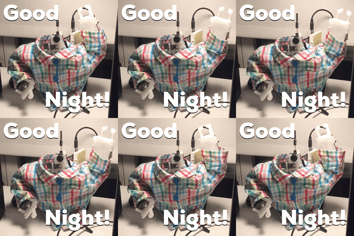
Similarly...

 primal shell
I had abandoned my earlier plans, only just now considered it again
jolly badge
haha I will keep you posted on my plans. August is the plan unless we are stuck in NJ based on covid TBD
We will rent up there until I can find the right property since I need 10Gbps, no-zoning laws, and a ton of land.
Anything with the house needs my wife chooses that's all her since I'll be in my own lab on the property haha.
primal shell
Act 250 covers a bunch of the state, there are some gores that are free of zoning but they're not large.
jolly badge
yeah and then removing from current use I'd have to do as well
so I want to be up there renting when I search since 4hr drive for 1 day of 6 houses hunting was exhausting
I did find "the one" but then saw it's part of zoning so I'd never get to build what I want there
I just want enough acres to be able to build cool tech stuff with others who want to come hang out. 3d printers, metal lathes, cnc machines, go kart track, theme airbnb's, arcade, etc
and I dont need neighbors feeling like skynet is here yet when I have my fleet of drones for my family.
primal shell
Sounds like the Northeast Kingdom
jolly badge
Going to do it around Springfield VT since that's where VTel services and their HQ is.
Vermont Telephone Company
Towns We Service Killington Bridgewater Hartland Cuttingsville Middletown Springs Wallingford Mount Holly Pawlet Danby Springfield Chester Grafton Saxtons River Need Help? We are happy to…
I also really want to look into land based robots
So I can have it carry bags, supplies, food to the visitors
since drones can only carry so much weight before you make it as loud as a helicopter
all fun stuff I'll continue researching at night 🙂
primal shell
These might be useful for a land based robot https://www.allelectronics.com/item/dcm-2430/24-vdc-300-watt-brushless-motor/1.html

All Electronics Corp.
MAC-BMC P/N 12500 2. Powerful brushless motor with built-in 30A motor speed controller. Designed for electric scooters. Great low-end torque. Requires 5K Ohm potentiometer or Hall-effect throttle to interface with speed control. Great motor for battlebots, hobbyists and experi...
sly sand
I need more 3" and 6" Premium Jumpers!! I have had to rob jumpers from my Little Red Rover in order to wire up my two RFM69 radio nodes. I need other things too so I can move forward with my MESH Network and robot project.
primal shell
Ordinary bell wire works in a pinch (I use it a lot)
sly sand
I know, but I do not want to make jumper wires. 😜
Ordinary bell wire works in a pinch (I use it a lot)
@primal shell Wait, is that solid core? Does it come in great colors?
primal shell
It's solid core. Ordinary 2-pair phone cable has red, green, black, and yellow. 3 pair adds (I think) white and brown. Solid core ethernet cable has 4 pairs of striped wires (blue, orange, green, and brown with white). A 25-pair phone cable has a a bunch of colors in striped pairs.
The striped pairs have one with the major color with a minor stripe (such as blue with white) and the opposite (such as white with blue).
sly sand
That 25-pair phone must me stranded core, right?
dry prawn
nah, solid so it can be punched down
sly sand
What gauge is that 25-pair phone cable?
dry prawn
maybe 20 or 22 gauge
heavier than the 24 gauge of cat5 I think
or it is 24 gauge and I'm off: https://www.discount-low-voltage.com/Cable/Cat3-Telephone-Wire-Cable/BC3RI5024GYCO
sly sand
I think 22 gauge would be ideal for breadboard jumper usage.
primal shell
I managed to get permission to pull some phone cable out of a building that was being demolished. I only grabbed like 5 meters of cable, but that's 50 5 meter long wires: a quarter-kilometer of wire. That was years ago, and I'm still using it.
sly sand
Wow! I really like to color code my connections with certain colors. Red/Black for power/ground, Yellow/Green for SDA/SCL, and Purple/Orange/Grey/White/Brown for SCK/MISO/MOSI/RESET/CS. That does not leave any colors for other stuff though, but does cover the most important things I use. It would be nice to have other colors too, whether striped or solid, though. 😉 🙂
primal shell
Still leaves blue 
I like using consistent colors too.
I tend to use yellow for clock, for both SPI and I2C (and other clocked protocols)
 naive fulcrum
I am trying to find the part: https://www.adafruit.com/product/3986 to help read the RPMs of a motor. If I search the component type on digikey the prices are all $50+ compared to $3 on Adafruit. Is there something I'm missing or another similar part anyone is aware of? Something like https://www.digikey.ca/product-detail/en/tt-electronics-optek-technology/OPB626/365-1666-ND/1636994 or https://www.digikey.ca/product-detail/en/tt-electronics-optek-technology/OPB200/365-1918-ND/1636789 ? Thanks
primal shell
I like reflective sensors for that kind of duty, then instead of needing to block the light, you just need a light (or dark) spot on your rotating assembly and you aim the sensor at that. One possibility is https://www.adafruit.com/product/3930, another is https://www.digikey.ca/product-detail/en/american-bright-optoelectronics-corporation/BPR-301/BPR-301-ND/9678549
naive fulcrum
Oh cool, thanks. So like painting a bit white splot on a wheel and aim it at where that would pass?
primal shell
Yes. If you don't want a permanent mark, you can stick on a bit of tape (metallic tape works great if you have some)
Here's how one person does it https://softsolder.com/2014/10/21/sewing-machine-rpm-sensing-gun-bluing-ftw/
naive fulcrum
Thanks that makes sense.
 worn bobcat
Excuse me. I am looking for an article about putting a Raspberry Pi and a 16x IR sensor on a Roomba Create, but I am strictly a beginner. Is this considered outside a beginner level project? I want it to motor around my basement with a RPi camera and a WiFi server - I once read something in a magazine that said people do this. Am I crazy?
sly sand
@worn bobcat If you are crazy, you are not any more crazy than any of us here. 🙂 If you feel like you can handle the project then go for it. The best way to learn is to jump in with both feet and just do it. That works quite well for me! 😉 🙂 Not only do people do this but they do much crazier things! 🙂
I am working on two small robots. 🙂
 honest anvil
Hello . Anyone has experience in robotic arm?
primal shell
Yes, this one https://www.adafruit.com/product/548
naive fulcrum
@primal shell just wanted to say thanks, I got that part you recommended, had to learn how to wire it up and switch to 3v signal (learning is good) and it works perfectly!
primal shell
Cool, I'm glad it worked for you! And I agree, learning is good!
honest anvil
https://youtu.be/Iy_iRwYq-a0
6dof. I got this kit with 16 servo controller board(Bluetooth/usb)
But it’s software & connectivity is bad.
I want to control it via wifi. @primal shell

In this experiment, we tested a robotic arm.
Our robotic arm has 6 Degree of freedom which means it has 6 joints(servo motors).
So we’re lifting a AA Battery(23g) with the arm & putting it into a round box.
1⃣ Robotic Arm 6 DOF Aluminium Clamp DIY With 18 Servo Controller:...
primal shell
You could use a WiFi capable Arduino such as https://www.adafruit.com/product/4000 along with a 16-channel servo shield like https://www.adafruit.com/product/1411 to control that arm.
honest anvil
Thank you @primal shell
 indigo dirge
Hey, I bought an aluminium 6dof robot arm including servo's, that I need electronics for since it only includes the servos.
I can't really find anything dedicated for such a thing?
Have a strong preference for being able to program it with Circuitpython.
Maybe a 8-Channel PWM/Servo FeatherWing, but would that be able to drive four MG996R metal gear servos and two MG90S metal gear gear servos?
 red dirge
@indigo dirge The input to servos is just a PWM logic signal. You'll need to provide enough power for them on the power lines, but unlike steppers, the "driver" doesn't actually drive the motor itself. So, yes, if you have at least 6 channels of PWM output you should be fine. Just make sure you either have a separate supply or good isolation for the motor power lines.
indigo dirge
@red dirge thanks for the info, now I understand why there are no specs on power are given.
I have a lab power supply, that should do plenty
And a Feather M4 should be plenty to run code on right?
Already found the tutorial on what Circuitpython libraries to load
But it seems the actual programming it 'just' entering some commands by guessing, run it, and then adjust the program in small steps?
Was hoping for more complex kinematics, by using special software on a Pi or something
And have the Pi run it to the featherwing
Can't find anything that looks like a complete project, its either half finished or extremely dated
red dirge
Certainly you can write a program to do something with the arm on a feather. Really you are just outputting sequences of 6 different numbers. Not much compute in that. However, if you decide to get serious about robotics and use software for path planning, etc, you may be better off with a pi. In that case I wouldn't bother with the feather at all, and just attach a servo driver directly to the pi and use real Python instead of micropython
indigo dirge
yeah I had the same thought
looks like a Adafruit 16-Channel PWM / Servo HAT is a better option
although since the featherwing only needs I2C, could also connect that to a PI
Do you know of any GUI driven software for a PI?
red dirge
Robotics is a pretty big field. You will certainly find a lot more linux robotics software than something for micropython. I don't have anything specific to suggest for GUI control of a 6 axis arm, though. While certainly you can connect anything I2C to a Pi, you will almost certainly get better software integration with a Hat.
indigo dirge
well thanks for the advice
Ill order a hat, and look further in software and guides in the meantime
sly sand
@indigo dirge Where did you buy the arm? Is it a kit? If it is a kit, you should be able to get at least some software for the arm from the manufacturer. Also, google for the name of the arm and see what comes up.
indigo dirge
@sly sand https://www.banggood.com/6DOF-Mechanical-Robot-Arm-Claw-With-Servos-For-Robotics-Arduino-DIY-Kit-p-1256135.html?rmmds=myorder&cur_warehouse=CZ
I paid E85 for it.
Manufacturer provides an assembly guide, and that's it.
But they sell it with only the servos, so that makes sense imo.
And even if they provided some example code, it would likely be with some Arduino.
I highly prefer python, since that's what Im learning right now as my first programming language.

www.banggood.com
Online Shopping at Banggood.com!
primal shell
It's possible to run servos with Python (my first thought is MicroPython or CircuitPython and a PWM board).
If you had something more powerful like a Pi, you could hang a PWM board off of some GPIOs and run it fairly easily with Python (the Blinka library might contain useful libraries for that approach)
sly sand
@indigo dirge Unfortunately, you are going to be responsible for writing all the software for this arm. Controlling the servos will not be a problem, but you will have to do some research to figure out how to write the code. There are tutorials to learn kinematics and such, but there may not be any Python coding examples.
indigo dirge
I'm sorta surprised these are not more guides/tutorials out there, since there are a ton of these things sold on these sites.
And they surely are not suitable for production uses, so its all for education or simple projects.
primal shell
One nice thing about Python is that it's fairly straightforward to convert a description, equation, or pseudocode into working code.
indigo dirge
is why I'm learning it, its like a tool that lends itself to so many fields/uses
And yes, I will start using a Pi3 for it, with a Adafruit 16-Channel PWM / Servo HAT to connect the servo's.
sly sand
@indigo dirge You will have to google for terms like "kinematics," "inverse kinematics," etc. There are plenty of tutorials out there but you have to do a proper search to find them.
primal shell
Some of the DIY magazines have some nice introductory kinematics articles.
indigo dirge
Interesting. Got any links?
sly sand
Two of my favorite magazines are SERVO and Nuts & Volts. SERVO has a lot of great tutorials, including controlling arms in various languages.
You can also add "python" to any of your searches to find stuff written in Python.
indigo dirge
sure
primal shell
I think Hackspace, Diyode, and Elektor have had recent articles on the subject
 supple moon
@indigo dirge that is a cool looking arm. That scissor design looks like it will be quite interesting to program to say, make it extend outward and keep the 'hand' end level. I have been looking around for designs for an arm, but haven't decided yet.
Anyone here have experience with can bus? I don't think adafruit has a can bus product. Most that are sold are designed to interface with a car - which is not what I want to do. I am looking to upgrade from I2C for communication from different 'smart' systems. I mentor a FRC robotics team and ALL the motor controllers and other systems connect via can bus. It is so easy to wire. Unfortunately there doesn't seem to be a good easy standard for using can bus other than a manufactured product and their drivers. I am looking to take a can bus decoder, a M0/M4 something and a motor driver to make a 'smart' motor controller that is connected by can bus. Anyone make something like that?
lone skiff
A number of microcontrollers have a CAN peripheral, though you do need an external transceiver to interface to the bus voltages. STM32 has both M0 and M4 chips that would be fine for that.
supple moon
Can you explain more? If the microcontroller has a CAN peripheral why do you need an external transceiver? That is just for the CAN voltages of 3.75/1.25 to converted to 3.3/0? So the STM32 has a can bus port just like it would have I2C and SPI? I looked at the ATSAMD boards and didn't see that ability.
lone skiff
Yeah, the transceiver is for voltage conversion and isolation. Similar to how there's logic-level UARTs versus serial-port RS-232 voltages. And yeah, the chip would have a CAN peripheral just like I2C/SPI. In the Microchip family, you'd want to look at the SAMC, E, or V series.
The CAN peripherals are generally a bit more complex, more like Ethernet than a UART, since CAN is a packet-based protocol rather than simple byte-based.
supple moon
Gotcha. Sounds like a bit more of a challenge, but I think I will look into it more. Thanks.
left coral
On the other hand, it gives you some of that packetization framework for free that you'd otherwise implement on your UART anyway.
and gives you multi-drop priority-based bus arbitration as a matter of course, instead of being something you also need to implement yourself.
(in short: I really like CAN. I also love Ethernet)
As a note, if you absolutely must use some existing MCU, there exist CAN controllers (not just transceivers) that you can talk to over SPI
e.g. Microchip's MCP2518FD
(implemented on a breakout board here): https://www.mikroe.com/mcp2518fd-click

MikroElektronika
MCP2518FD click is a complete CAN solution, which can be used as a control node in a CAN network. MIKROE-3060 Microchip MCP2518FD ATA6563
that there seem to be some drivers for online.
lone skiff
Thanks @left coral, I totally forgot that the SPI controller option also existed... very handy. 👍
supple moon
So does this thing from seeed https://www.seeedstudio.com/Serial-CAN-BUS-Module-based-on-MCP2551-and-MCP2515.html that you pass rx/tx into a similar thing? Or does it rely more on lower level software?

longan, CAN-Bus, can bus shield, can, obd, can bus, obd2, car, vehicle, Arduino, grove, seeeduino, raspberry
lone skiff
Looks like that's an extra level up... it's got a little AVR microcontroller on it so you can use an AT serial command set to talk to it, and then it uses the SPI controller to actually speak CAN to a transceiver.
worn bobcat
Has anyone used a good 16x I2C board? I am trying to combine a bunch of IR distance sensors into a single interface. I think I saw one on "tindie" (maybe the name) but was looking for someone with experience. I could not find this on Adafruit. Thank you.
left coral
I'm not sure how many addresses you can configure your IR sensors to, but this could work for you: https://www.adafruit.com/product/2717

You just found the perfect I2C sensor, and you want to wire up two or three or more of them to your Arduino when you realize "Uh oh, this chip has a fixed I2C address, and from what I ...
worn bobcat
Thank you. Sixteen (16). I will look. I appreciate your quick response.
left coral
The reason I suggest this board is because I assume your problem is that you have more IR distance sensors than you have available I2C addresses
so you would have multiple sensors with the same address
worn bobcat
Yes
left coral
These chips are I2C bus switches that you can in fact configure over I2C
so you can put one sensor on each of the downstream busses
(and these chips have up to 8 addresses themselves)
worn bobcat
Thanks. I will look at thing and try one.
left coral
You'll need 2 of these boards, but should scale nicely
worn bobcat
Thank you, electronic_harry.
worn bobcat
This is the device: "OctosonarX2 - connect 16 x HC-SR04 to Arduino"
primal shell
That one appears to use a PCF8575 I2C GPIO expander (using a single I2C address) to provide individual access to ordinary (non I2C) sonar transducers.
worn bobcat
Is that a bad thing? Are non-I2C sonar transducers inferior? (I know they are inexpensive.)
lone skiff
They're a bit more low-level, giving you the raw echo timing for the microcontroller to interpret, whereas something on I2C would typically have the distance-measuring logic built-in, and you'd just read out the answer as a register value.
worn bobcat
Yjaml you, EdKeyes, that's very helpful.
worn bobcat
*Thank you (typing while I looked behind me)
supple moon
@worn bobcat I used one of those I2C multiplexers with 8 Adafruit ToF sensors. It worded really well. Easy to pick sensors on software side. Otherwise you use the same code.
worn bobcat
@supple moon, thank you. My board and components should ship today. 🙂
 plain drift
Would using an IMU would give significantly more accurate readings than using a gyro + accelerometer combo to get the tilt angle? Building a self-balancing robot
lone skiff
It's not clear what you mean by "IMU" there, since usually they are exactly a gyro+accel combo.
primal shell
For more accuracy, you might be able to use angular encoders or distance measurement from the platform to the ground.
sly sand
@lone skiff An IMU usually has an accelerometer, gyro, and a magnetometer.
@plain drift With an accelerometer and gyro you can do what is called sensor fusion to combine the readings for better accuracy and stability.
plain drift
@sly sand thanks, but would sensor fusion be less accurate than getting readings directly from an IMU?
primal shell
Sensor fusion is what the IMU does, basically, whether it's done on the IMU itself or the IMU readings are fused by software on the controller.
For higher accuracy, it's generally fancier algorithms or other sensors (like distance or rotation).
 unreal jetty
Hi! I'm building a little robot, and I was wondering if you guys could help me figure out what a part would be called, so I can find it online
I need to be able to actuate a wheel up in one direction, then also be able to control the wheel and spin it in either direction
Heres a sketch!
Itll be pressed up to hit the surface of the rod above it, then it needs to spin the wheel to move the rod left and right. Any ideas?
maybe I should use an elastic belt and have the wheel not be powered, just actuated? Drive the belt from a separate motor?
I was just wondering if theres a common part that would solve this problem, or if I should try to design a system for it!
left coral
There might be something that would work for you if you take apart a printer
This seems like a problem they would have solved
unreal jetty
Oooh! I love that. You're right... I think they have a bar that comes down then spins to advance the paper
left coral
and I think they also generally need to be able to reverse the paper out
sly sand
@sly sand thanks, but would sensor fusion be less accurate than getting readings directly from an IMU?
@plain drift You can not do much with the raw readings from an IMU. That is why they should be combined using some kind of sensor fusion algorythm. The result will be much better than just the readings by themselves.
supple moon
@unreal jetty is it the vertical motion you are looking for? There are several ways to get the motion, but A linear actuator might be the easiest. Then are not cheap, which tends to push people to cable and chain solutions. How far up is it? Linear actuators don’t go that far or get really big. Which ever you go with you would have a separate motor that turns the wheel. If you have space for the motor at the top that’s usually easiest.
unreal jetty
I need the vertical + rotation control.
It is a small piece. Whole thing needs to be able to fit in my hand
supple moon
Oh boy. That’s more of a challenge then.
primal shell
supple moon
Wow, that is small.
 vital quartz
@indigo dirge hey it was very old post from you but where did you manage to find 6 dof 3d inverse kinematics? Iirc that is quite complicated math and if there is a library I'd like to find it too. (Also we have used ros to control a robot which has really big libraries and simulation things, too, but it runs on raspberry pis not exactly on microcontrollers. It does communicate over serial though)
plain drift
Hello anyone know if this motor will work with this driver? The current ratings match up, and the max voltage of the driver is well above that of the motor, but I'm not sure what else I need to check. Thank you!
https://usa.banggood.com/A4988-Driver-Module-Stepper-Motor-Driver-Board-with-Heatsink-p-1577464.html?gmcCountry=US¤cy=USD&createTmp=1&utm_source=googleshopping&utm_medium=cpc_bgs&utm_content=frank&utm_campaign=ssc-usg-100-all-0821&ad_id=378825333488&gclid=CjwKCAjwnIr1BRAWEiwA6GpwNfYNSJNq3D3C0tG36qjXrcoETLJxiYPG3Z9JmVkx5oePTBbtcIdVRRoCIAkQAvD_BwE&cur_warehouse=CN#customerQA
https://www.aliexpress.com/item/32572890101.html?aff_platform=product&sk=nMVrRJu&aff_trace_key=7a928ae6a0e643458f2929bd00a75edb-1587789397508-03284-nMVrRJu&terminal_id=6b5988cdb90b4abc899ae681b047ba1f&aff_request_id=7a928ae6a0e643458f2929bd00a75edb-1587789397508-03284-nMVrRJu

aliexpress.com
Smarter Shopping, Better Living! Aliexpress.com

www.banggood.com
Online Shopping at Banggood.com!
 arctic viper
I need a lightweight structural metal similar to Meccano's erector set. I've been racking my brain for search terms all day.
lone skiff
Maybe explore here? https://www.mcmaster.com/structural-framing
McMaster-Carr is the complete source for your plant with over 595,000 products. 98% of products ordered ship from stock and deliver same or next day.
arctic viper
@lone skiff , thanks. I've looked there. The smallest and lightest perforated angle they have is 1"x1"x⅛". I'm trying to build a mechanical structure to go /inside/ a 3"x3" square tubing.
Oh, yeah, forgot about the "L-Shaped Bolt-Together Framing" At least it's thinner, but at 1¼"x1¼", it's getting pretty crowded.... Still, might be my best option.
 versed fern
@arctic viper maybe this would work for you http://microrax.com/
 verbal ibex
Hi all I had a quick question, regarding the l289n motor controllers
would you say it is reliable for the long run?
vital quartz
They probably are with adequate cooling and reasonable loads
naive fulcrum
Is it possible to share the I2C bus on a Crickit with another device (in this case a LSM9DS1 sensor). As far as I can tell the bus is locked, just making sure I'm not missing something
lone skiff
What do you mean by "locked"?
naive fulcrum
I tried i2c = busio.I2C(board.SCL, board.SDA) and received a message that SCL was in use.
Hmm just realized I forgot the () after the board.I2C() method that I tried second going to see if that will work
Thanks @lone skiff for being the person who asked a question and made finally notice my mistake, that was it, missing the lousy ()
 stable helm
anyone know where i can get details about pneumatic tubing? I'm trying to figure out if i should go with 1/4" or 1/8" to drive some of my pneumatic cylinders.
vital quartz
I think only difference is resistance to flow, which means 1/8th probably requires little more pressure to get same amount of liquid through
I don't have reference in my head for 1/4th and 1/8th (metric gang) so don't know if that's air or hydraulics
stable helm
its for air
vital quartz
All else equal, for 1/4th the pressure in the tanks will get lower quicker but you'll have faster actuation on piston
This is really simplified version ofc because frankly I don't know near enough about pneumatics
Ohh also following all else equal 1/4th might be able to handle higher pressure tanks
stable helm
gotcha k thanks
dark magnet
I am working on an rc project and am wondering if I need anything between the Receiver and a coreless dc motor
Also I don’t know if this counts as robotics
primal shell
Depends on the receiver, but usually you'll need some sort of motor driver.
sly sand
@dark magnet I am also working on an RC project! The PWM output from a typical RC receiver can drive a servo directly but for DC motors you'll need a motor driver like @primal shell says. The L293D chip can drive DC motors and it seems to work with PWM input (not sure). There are motor driver boards available as well.
vital quartz
It does work with pwm
dark magnet
Thanks
sly sand
Hello guys! I need some help!
Question, how can I create a Write Cycle using logic gates?
lone skiff
I don't think there's a universal write cycle. It would depend on the thing being written to.
dense gull
Who has experience with DYNAMIXEL servos?
primal shell
I've read about them, but no real experience (I've been using Mechaduino ones)
 shy coral
Is there any dimensional drawing for the arms and levers for this? https://www.adafruit.com/product/169?gclid=Cj0KCQjw5J_mBRDVARIsAGqGLZB5GHTmju3CAAKUrHM-3LAq-hAVUDK1Z0ZcB-mEHObFf_Y4I38iuScaAsmEEALw_wcB

Tiny little servo can rotate approximately 180 degrees (90 in each direction), and works just like the standard kinds you're used to but smaller. You can use any servo code, hardware or ...
Kinda hard to cad mechanics without dimensions
vital quartz
There should be cad of that in grabcad
@shy coral
The GrabCAD Library offers millions of free CAD designs, CAD files, and 3D models. Join the GrabCAD Community today to gain access and download!
primal shell
I ended up doing it manually with calipers.
vital quartz
That looks spot on 3d print
primal shell
That's actually an earlier version, I later reversed it so the horn hub goes through the 3D printed piece, pinning it between the horn and the servo for even more rigidity.
Another part, with both a horn recess and servo mounting
vital quartz
The part that's fascinating to me is how precise your print is
Our prints are wavy
Can't decrease layer height because then something funny goes on with extruder, it over extrudes some parts and under extrudes some parts
primal shell
I am quite fond of that printer.
shy coral
@vital quartz Thank you
shy coral
Design draft complete! https://cdn.discordapp.com/attachments/290937873392205834/708722205319495790/unknown.png
https://cdn.discordapp.com/attachments/290937873392205834/708722275725213737/unknown.png


 vital quartz
Hmm air circulator?
shy coral
For a home made ac circulation system
red dirge
Looks like a robot to me. It has a servo controlling the louvers! 😃
 weak kelp
robot body with AC
shy coral
It was mostly a followup on my question about servos the other night
Also, technically, afaik, Robotics is the study of everything automated
vital quartz
Actually robots doesn't have to be automated
Ohhh are we gonna do what's robot or not discussion?
sly sand
A robot is autonomous. Anything else is just a machine controlled by somebody.
vital quartz
There are surgical robots that are controlled by doctor
sly sand
Those are not robots.
vital quartz
Or there are Tele operated robots
sly sand
Those are also not robots
vital quartz
What is robot is philosophical question.
sly sand
What do you mean where and who?
shy coral
Yeah, but robotics is a bit different from a robot 😛
vital quartz
They can be semi autonomous which is tele operated
shy coral
from wiki "The goal of robotics is to design intelligent machines that can help and assist humans in their day-to-day lives and keep everyone safe"
sly sand
There is no such thing as a semi-autonomous robot. Tele-operated machines are not robots.
vital quartz
You can't narrow robotics down to automation
sly sand
I am giving the definition of a robot, nothing else.
shy coral
I gave my source.
vital quartz
I gave my source.
wiki says there are semi-automated robots too
shy coral
Yeah. And I agree with you
Even a toaster can be argued is a robot if it has more settings than just heat. If it monitors and judges.
vital quartz
If you got a moment i can bring up teleoperated robot articles from IEEE research database
sly sand
Do you believe everything you read on the internet? So far, I have not found a correct definition of what a robot is. The term has been diluted and incorrectly broadened.
vital quartz
I'm saying IEEE research database
red dirge
So, geekguy, if you programmed a sequence of actions into a robot arm, but had to press a button to initiate the sequence, would that be a robot or not? All definitions change over time. That's why the OED exists :^)
red dirge
There is no such thing as a robot which does not require a human to, at some point, initiate its activity...
vital quartz
Literally global standards
shy coral
We have industrial Robots at work, they have 0 intelligence other than cameras, color matching and actions. They are still called robots. "Packaging Robot"
red dirge
Anyway, this discussion may need to move to help-with-english
sly sand
Actually, it depends on how the machine behaves, whether it is a robot or not. If the machine can perform without intervention from a person and is not controlled by a finite program, it is a robot.
shy coral
All programs are finite, either purposeful or by other factors. Even humans end at some point.
vital quartz
This one discusses differences between human interaction and non human interaction
there are whole field of research about robot human interaction
sly sand
If, however, the machine can alter the path it takes or action it performs based on inputs from sensors including cameras, and does not require human intervention, it is a robot.
shy coral
By that definition, any machine with a "if"-statement is a robot
sly sand
Not true.
vital quartz
and those papers sometimes get revised like 5 times and journals ooof if you got it 5th time you're very hardworking man
red dirge
You might have fun looking up the historical meaning of the word "nice".
vital quartz
@sly sand bro I'm showing examples from IEEE Xplore still waiting something against those.
shy coral
I agree. Please provide sources
sly sand
@vital quartz "still waiting something against those" does not make sense.
vital quartz
an argument to deny my sources.
shy coral
https://robots.ieee.org/robots/titan/ These are classified as robots by IEEE, their programs generally do not take sensor values into account. In certain situations, they can be equipped with cameras to find certain locations, but the normal case is a straight forward program "Go point A, Pick Object, Go Point B, Drop Object" kind of thing.

The Titan is the strongest robot arm in the world, with a payload capacity of over 1,000 kg (2,200 lb). That's enough to lift aircraft parts, marble blocks, and more than a dozen roboticists.
vital quartz
Pointing out my unrelated mistakes doesn't eliminate my points and examples. 👀
shy coral
I do agree that in modern media, the term have become a bit too broad. However! Language and definitions change over time.
vital quartz
It has evolved that's why its broad
shy coral
Also, fact remains that this channel is not called #help-with-robots, but #help-with-robotics. Robotics and Robots are linked, but not necessarily the same.
vital quartz
mechanical engineering evolved and there become sub genres of it thermodynamics dynamics statics fluids etc.
shy coral
My EE program was called "Mechatronics; Interaction between human and machine". It was later renamed to just "Robotics" to reflect the change in the field
vital quartz
anyone feel free to ping me about it but i have something else to do right now
shy coral
I shall go do something more productive like playing call of duty.
sly sand
@vital quartz I am not denying your sources. I just pointed out that part of your statement does not make sense to me.
shy coral
Also, I'd like to ping a <@&327289013561982976> to clarify this topic for us. What exactly is plausible in this channel. In my humble opinion it is anything involving automated movement. Since there is no other topic better fit for the purpose. And since @primal shell tagged my post, I rudely choose you 🙂
red dirge
Alas, he is a community helper, not a moderator!
shy coral
Yeah, but he is quite active and might know whom to dare ping to get assistance 🙂
primal shell
It's as easy as tagging <@&327289013561982976>
shy coral
I was just brushing up on my rules 🙂
red dirge
Ahh, the safest thing to do when someone is trolling is to just let them lie ... take that however you like 🙂
vital quartz
@vital quartz I am not denying your sources. I just pointed out that part of your statement does not make sense to me.
@sly sand It might not at first but that's how things evolved into 🙂
I think that's cool because you start to see things like social interaction
like those pet robots react with you and play games with you
red dirge
@shy coral I cannot imagine he was seriously objecting to your question being here. Seemed a very reasonable question to me for this channel, regardless of definitions.
vital quartz
or I know a guy working on negotiation robot
shy coral
Also, Automated and Controllable Home Air Conditioning utilizing several different motors for adjusting air flow and fan control and also talking and communicating with the home AC unit should be classifiable as A robotic project 🙂
 pine fable
@shy coral I'd say this channel is largely community driven so if the community of this channel feel that it's on topic, it is
if members disagree they should do it politely, respecting the opinion of others and showing that respect by refraining from judgement or belittling ideas
On the flip side, a person putting forward an idea should "read the room" so to speak and try to notice when they're "pushing the rope"
shy coral
Thank you~ 🙇
pine fable
"objective" statements will generally not help move conversation along. Saying "X is true. Y is wrong, Z is <inflexible statement>" while they may well be factually correct are not good ways to build consensus and foster open and inclusive conversation
vital quartz
siddacious thanks for clarification but i don't think anyone was hostile during conversation (at least I wasn't) and if i seem to be at any point I'm open to change my wording or behaviour
pine fable
My comments above are non-specific and not meant to be pointed in any particular direction
sly sand
@primal shell They do not like you tagging roles like that unless it is REALLY necessary.
 idle valve
@sly sand Please do not attempt to speak for the moderation team. Wether a user other than you is right or not to ping the Community Moderators is not for you to decide. As Siddacious is a Community Moderator and has already commented on the matter, you shouldn't worry about it unless it is your actions or the actions of others persist.
Further, if you think the act of another warrants the attention of a moderator, you can ping the Community monitors or bring it to the attention of one of us via DMs, where we can then take care of it. Getting involved in other ways only drags you into it and can escalate issues despite anyone's best intentions.
sly sand
@idle valve The issue @pine fable was referring to did not have anything to do with pinging community moderators. If you will look at the sequence of comments on this channel, you will see that my comment about pinging community moderators was after @pine fable spoke up. I think he was actually referring to a discussion about what a robot is that several of us were having earlier.
idle valve
Madbodget's comment was part of the same conversation. Roze asked Madbodger who to ping. The answer was a Community Moderator.
My greater point stands regardless of if that ping was excessive or not. That is for us to decide, not you. Please refrain from putting your views of what is right on others as though it were the only one - In many ways, it is already clear that it differs from what we are going for. This applies to all - If we have seven different uncoordinated people trying to tell others what can and can't be done, it ends in confusion.
It's not your job, you don't need to worry about it. As I said, if you see something that you think is amiss, you can ping the Community Moderators or DM one of us, and we will take care of it.
sly sand
@idle valve In any case, it no longer matters to me. I quit. Goodbye. @pine fable
 granite burrow
Hey guys I got some low cost A4988 step stick and they make a lot of noise, surprisingly to me even when the stepper is stationary (with motor enabled). I got some of the quieter Trinamic TMC drivers and they were a lot quieter. I’m just wondering if I got a rogue batch of low end A4988 boards, or is this noise just to be expected with this A4988chipset?
vital quartz
Noise is expected
And if you use microstepping that's why they make noise even though steppers not moving just enabled
granite burrow
@vital quartz I definitely had micro stepping on. Now I’ll have to go back and try it without so I can recheck the sound level, maybe I can get some use out of these A4988 boards that way. Thanks for the hint!
vital quartz
Np man
 fast steppe
Hey, I have a l298n motor driver. If I power it with 5v, will the input logic still be compatible with a Raspberry Pi?
I'm guessing yes because of the data sheet, but can someone please confirm?
Oh, it's one of these breakouts with I think are called STEMMA connectors.
 thin thicket
hi guys
i need some assistance please if any one can help me
iam having a research in my univeristy and to be honest iam only aware of the idea , however i don't know anything about the procedures and calculations
i need to design and to sketch this one and drive it's mathmatical expressions to get the block diagram
any ideas ?
versed fern
As akir suggested you want a PID system. I would start here if you haven't already https://en.wikipedia.org/wiki/PID_controller check out the generic PID block diagrams. Since it's a linear CNC system I'd imagine you'll be using some sort of ball screw or rack and pinion system. That means that you'll be actuating the linear movement by spinning a servo motor to turn the move the axes end effector. So you'll need to keep track of the servo motors rotations and homeing (that is giving it a starting point typically at one end of the linear axis that you always know it's position from.)
A proportional–integral–derivative controller (PID controller or three-term controller) is a control loop mechanism employing feedback that is widely used in industrial control systems and a variety of other applications requiring continuously modulated control. A PID controll...
 shy parrot
I’m working on a CNC axis, and I’ve noticed that my steppers seem to sometimes get “stuck” and don’t want to move. sometimes it moves all the way, part of the way or just kinda jerks a bit. Without power they move freely, and it happens with a different stepper motor with no load, so I’m sure it’s something with my SKR 1.3 smoothieboard, tmc2208 drivers or my wiring. Does anyone have a good article on stepper motor troubleshooting? All the ones I’ve found are either no movement at all and making noise, or a bad driver/board, or config.
Quick video of moving it 10mm a few times in different directions. Steppers are 17HS19-2004S1, controller is SKR 1.3, with TMC2208 controlled via UART.
primal shell
Many stepper driver boards have configurable current, yours may be set wrong. It could be the steppers are miswired, so they're not phased correctly. It could also be a supply voltage problem, either directly, or due to a poor connection somewhere. Yet another possibility is that they're trying to accelerate or move too fast.
shy parrot
ahh thank you! I tried to look up what an incorrect stepper VREF would sound/look like, but couldn't find it. If this fixes it I'll have to post that video 🙂
shy parrot
Well it was far dumber than the VREF being wrong, I started over setting everything up, and I had initially missed the jumpers under the TMC2208's which were set to SPI mode for the TMC2130 as well as the jumpers for UART on the TMC2208. Once I removed those jumpers the motor is happily doing exactly what it's supposed to.
 quasi stump
does any know how i could control a larger servo (that has a controller) like step and direction with circuit python
red dirge
@quasi stump I'm sure someone can help easily, but you will have to be a little more specific. All servos "have controllers" in one sense. Are you saying you have a servo, and a separate motor control board (which sends PWM to the servo), or do you just have a servo you are directly connecting to a device? What device are you running CircutPython on? If you have an external controller in addition to the servo itself, which one. All of these things impact the answer...
quasi stump
@red dirge it has a controller that uses step and direction, and im like to use a Grand Central M4 Express. I taked with someone else who recomened just a PLC which i may just do that as it looks easier
red dirge
Step and direction sounds like a stepper motor, not a servo. Two completely different things.
 untold loom
I'm looking for a messaging protocol that is relatively easy to use in CircuitPython and C/C++ and can be routed over both serial and UDP so that my main control MCU, motor control/safe drive MCU, OpenMV camera, and laptop can talk to each other.
I could write one using pack or something, but I'd rather use something off the shelf if it exists.
 toxic fog
@untold loom this is the closest to your description I know of https://www.pjon.org/

Open-source, decentralized networking for makers!
 twin chasm
Does circuit python have a MQTT or ZeroMQ library? MQTT can work over MQTT but ZeroMQ is design for it if I remember correctly
Huh, PJON is pretty interesting but is it a messaging protocol?
untold loom
Yeah, I've had good luck with PJON on arduino, but as far as I know there is no CircuitPython support for it.
There is an MQTT library for TCP, but that won't work over serial.
twin chasm
MQTT can work over UDP too I'm pretty sure
untold loom
It can and also over serial with MQTT-SN, but the CircuitPython library doesn't support that as far as I know
Also MQTT requires a broker
twin chasm
True, but your computer would be the broker
Then you could have multiple applications connect to it and exchange messages
untold loom
That would work if I added wifi adapters to everything. My plan is to use the main control MCU as a hub for everything on the robot, hence the serial requirement
twin chasm
Oh I see, I assumed the computer was the "hub"
Ooh I have an idea
CAN?
I have seen packages for CAN over serial or sockets
untold loom
Yeah, I was considering CAN to link the devices with a UDP bridge to my laptop
twin chasm
Looking more at PJON that's actually very cool. Solves the same problem some solutions I've made at work have. Good call out @toxic fog
untold loom
Yeah, PJON is really nice, but I'd have to port it to CircuitPython
twin chasm
I bet that would be a much welcome library #circuitpython-dev should get involved
untold loom
I'm just reluctant to port it because that's just a bit more work than I feel like putting into it right now
I was hoping to just find or make something quick and dirty so I can get to working on the control code
quasi stump
@red dirge its a closed loop servo motor that uses step and direction like a stepper motor, and i believe it may also takes other inputs maybe but the manual is in Chinese
red dirge
Ahh, I see. Hard to say much if it isn't standard and don't have a manual...
quasi stump
ya not sure if the other port of for configuration or it can do other things like control it, but i know it does take step and direction and have got the working
red dirge
Try google translate with the camera
quasi stump
i tried a bit and got the manufacture to translate some of it, im dont really think it does anything other than changes the configuration and setting
red dirge
post the model number and/or other info you have. Maybe someone will know more
quasi stump
HBs57 hybrid servo drive
the step and direction works like any other step motor controler
red dirge
Sure, but you're talking like there is only one way they work. Looks like the manual is pretty straightforward: https://www.damencnc.com/userdata/file/2134_HBS57.pdf
Is that the right one?
quasi stump
ya look pretty much the same
red dirge
Ok, then... Seems pretty straightforward. Connect the inputs on the controller to GPIO pins... What board are you running CircuitPython on?
quasi stump
metro m4 grand central
ive gotten it to work usign that just by pulsing on and of a digital out pin but my problem is im looking for a libary or something that can handle the position and set a max accelration and velocity
red dirge
Ahh. Ok, I think you now have a fully formed question, enough for me to say that I don't have an answer off the top of my head. It's quite possible that someone else here will, though... or you could try #help-with-circuitpython
quasi stump
ok thanks for the help
red dirge
Not sure I actually helped other than figuring out what you were looking for. Most of the CP libraries for steppers I'm aware of just focus on doing steps in various ways, rather than being higher level "speed/position" libraries. Sorry, done steppers, and done CP, just haven't really done them together 🙂
 crisp tendon
so im trying to turn 9v to 5v and when i was doing some researching i head u need a load can i use a led as a load
lone skiff
You don't necessarily need a load, but some cheap regulators don't provide a stable output without it, and they would vary in how much they might need.
crisp tendon
hmmm ok im using a trasitor
primal shell
You're using a transistor to convert 9V to 5V? The usual circuit uses a transistor and a zener diode.
sly sand
hello @everyone I'm working on a smart trash bin project it's basically a bin can catch thrown objects the object detection and the trajectory are captured by a kinect placed separately from the bin . I'm so far able to detect object and get its "depth and xy coordinates" the problem now how to calculate the trajectory of that flying object to tell later the bin where it should be placed to catch it ( im using python in this matter )
i would appreciate any help
primal shell
I figure if you get two samples, you can compute the direction between them, and move the can in the corresponding direction
sly sand
@primal shell sorry I didn't get what you mean exactly 😔 I'm thinking of using kalman filter still not sure how to implement this hopefully I will get sth out of it .
primal shell
I wasn't sure if you wanted to solve the hard problem (tracking an object in 3D space, computing the trajectory, and moving the can to the predicted endpoint), or the easy problem (which way to move the can).
sly sand
i already can track the object in 3D space i get out that the depth and x,y I still need to get the trajectory of that flying object to predict the endpoint .
 tender mulch
@sly sand It seems that is not a trivial problem, https://math.stackexchange.com/questions/2818251/how-to-predict-trajectory-of-a-moving-ball

Mathematics Stack Exchange
So I am working with python + opencv to predict the trajectory of a moving ball.
I am able to track the motion of the ball which is actually color tracking. However, I have no idea how can I predic...
sly sand
surely it's not thanks for the link it is helpful
tender mulch
look at the very end at the comment to noob-geek "treating the parabola as a lot of small linear (tangent) lines" makes it seem more manageable, not that I know how...
sly sand
i'll give you feed back about the final solution if i got one 😆
tender mulch
good luck!
sly sand
thank you
 somber plume
Looking to build a simple Arduino (or similar) compatible 3d printed robot to make with my new 3d printer for fun. Found some like Bob the biped and Otto - any recommendations?
primal shell
There are some clever quadruped robots out there (I'd share my design, but it's not finished yet).
 broken terrace
Hi all- I have a RPi3 with Crickit hat. Last week it worked fine, now i2cdetect doesn't show the Crickit and the green NeoPixel doesn't turn on. Swapping to a different Pi fixes it. Could I have fried the I2C port somehow?
twin chasm
Did you enable I2C?
If not @broken terrace -> https://www.raspberrypi-spy.co.uk/2014/11/enabling-the-i2c-interface-on-the-raspberry-pi/

The Raspberry Pi I2C (Inter-Integrated Circuit) bus can be enabled to allow a range of compatible sensors, screens and devices to be connected. This post shows how you can easily enable the I2C interface using a number of different methods.
broken terrace
I did enable I2C on the Pi- swapping to another Pi3+crickit with the same SD card solved it for now.
red dirge
If all of the hardware is exactly the same, including the SD card and one works and the other doesn't that does sound like the Pi may have gotten damaged.
broken terrace
To update, I think part of the problem may have been that I forgot to include a cap as required by my regulator datasheet. Power to my project is much more stable w less heat, and I haven't fried another Pi or Crickit 🙂
Next robotics question: I'm constantly breaking these tiny tabs on my TT motors:
Is this normal? I've broken 3 motors this way now.
vital quartz
I'd not say normal but probably expected give it some mechanical support after you made sure you soldered it well
IMO best solution would be epoxy or superglue but probably some electrical tape would work too
broken terrace
Thanks- I'm going to try again with a lighter gauge wire and yeah, I'll mechanically secure the wire end to the yellow case.
primal shell
@somber plume Making progress on the quadruped robot design
broken terrace
Very cool! That's a lot of servo headers on the PCB, and a regulator (and missing a cap, if that's just like what I'm building :)). What are you planning to power it with?
(Aside, on my mechanical stress issue I implemented the suggestion from @vital quartz and it's working well)
primal shell
Planning on powering it from a couple of lithium cells, using a UBEC to power the servos, and the onboard regulator on the Arduino.
stable helm
i want to put a stationary motor in the middle of a threaded rod and move the threaded rod back and forth. what kind of motor can do this?
primal shell
Usually there's a motor at one end, and a nut that moves back and forth. You could use a double-shaft motor, but then you couldn't be able to move from one end to the other (maybe this is what you want, I'm not sure). Alternatively you could be asking if you had a fixed (non rotating) rod, and you wanted the motor to spin a nut along the rod somehow?
stable helm
i saw the motors on the end. i was imagining something like this
but with a longer rod
looks like it's called a hollow shaft stepper motor
primal shell
Yeah, those are a little unusual, but as you pointed out, they exist.
stable helm
that would need some weird mounting as well
i was originally thinking pneumatics but i don't know how the mounting would work
let me draw a pic of what im thinking
red = cylinder, black = rod, yellow is some kind of cnc'ed adapter, green is another rod
i don't know how i can do this cleanly. especially mounting the green rod.
the green rod has some stuff mounted to it so i cannot put a bunch of stationary mountings for stability
primal shell
Sounds like you're describing a "linear actuator"
primal shell
If you can find someone with the old style satellite dishes, the positioning motors for those are linear actuators, fairly strong ones. Found one in someone's back yard a few weeks back.
stable helm
oh neat
yea these smaller ones look better
acutally even this might not work. my mounting space over laps with the work area
(back to mspaint)
so basically the gap between the orange lines is my "work area"
the stuff connected to the end of the green rod have to work in that profile
it's basically a slicing knife
we thought about using a blade but limited by space
thought about having a stationary knife mounted and moving the material but again restricted by space
ugh i hate upgrading existing hardware. too many limitations
primal shell
Tricky. Looks like your basic gantry arrangement.
stable helm
oh yea that might be a good way too
let me see if i cna find something cheap
actually maybe i can mount a motor to the very right, have a threaded rod like the green above, then move the slicer along the threaded rod
 wraith scaffold
Any recommendations for a high-precision robotic arm for scientific work? I found this ( https://store.ufactory.cc/products/uarm ) but looking to find other options as well

store.ufactory.cc
All-around gripper for inflated & non-planar objects It is the most widely used uArm applications by makers and hobbyists. The metallic gripper comes with a grasp range of 0 to 40mm, it can grasp objects as small as *** or as big as ****. This gripper is designed to maximize t...
something that is highly compatible with raspberry pi, like associated software or libraries, would be great also
versed fern
If you don't mind my asking what's your budget for the arm also if you have some idea of exactly what tolerance you need to hit that might help as well? The uArm is certainly not cheap as far as a lot of hobbyist robots go but would be considered very cheap compared to just about any industrial robot.
vital quartz
Is uarm actually any good? it doesn't really look like any traditional industrial ones. It looks more like toyish hobby ones. Do they have 3d inverse kinematics of uarm?
sly sand
hi,I just began in this world of robotics I have an arduino and some shields ,any recommendations about where to began ,maybe some free learning websites?
sly sand
Thanks, I would check them out
heady spire
Hi, how would I go about sending the following data in Python from a RasPi to a MiP robot? https://github.com/WowWeeLabs/MiP-BLE-Protocol/blob/master/MiP-Protocol.md I want directional movement control in Python 3.

GitHub
Documents to show the low level MiP command protocol, you can implement your own SDK using your preferred language. - WowWeeLabs/MiP-BLE-Protocol
 wicked jay
What kind of robots are building?
 tardy isle
hello, I have a question about building a quadruped involving the electronics
primal shell
What sort of question?
tardy isle
I'm working on the electronics and I was wondering if anyone knew how one would wire an 11.1 V 25C 2200mAH 3S battery to an arduino Mega, 12 MG996R 55g servos, 2 ultrasonic sensors, a lcd screen, and a bluetooth module
lone skiff
Wiring it up and getting it working in stages is probably recommended, as that's a lot of components to support all at once. The servos seem to need a voltage lower than 11V, so you'll probably want to add a buck converter to your design.
tender mulch
and you'll be at 2A +
tardy isle
would I want a 12V to 5V buck converter?
tender mulch
seems on the small side but https://www.adafruit.com/product/1385

Your power supply problems just got SOLVED! This little circuit board may look tiny but inside is a high efficiency DC/DC step-down converter which can output up to 3 Amp at 5V without the ...
tardy isle
ok, will order and try, thanks!
tender mulch
@tardy isle you probably want to go to a higher current rating, the servos are .17A each at idle
tardy isle
how much higher?
tender mulch
depends on how much work the servos are going to do, when stalled they are 1.4A each...
tender mulch
it's hard to say, i threw the link as an example but I think its too small - nice!
tardy isle
thanks 😄
tender mulch
maybe someone with more expertise in robots has a "rule of thumb" for servo current draw at that scale
tardy isle
do you think 5A would be a safe number?
tender mulch
absolute worst case (all servos stalled) it would draw about 17A so 5A is better, idk if it is sufficient in practice
tardy isle
hmm
tender mulch
a 10A unit for $10, not sure about its quality https://www.amazon.com/Converter-Adjustable-Battery-Power-Module/dp/B01H9642V0
but for $10 it might be worth a go, hook it up and see if you peak at more than 10A, if not it'll run cooler and last longer
tender mulch
you are welcome, let us know how it goes!
tardy isle
will do, I'll update when I hook everything up
 real kestrel
hi,I just began in this world of robotics I have an arduino and some shields ,any recommendations about where to began ,maybe some free learning websites?
@sly sand tinkercad.com is for me the best site, give it a try. (and you don't need to download it to use it)
I would make a homemade NERF, can someone give me a tip (or help me) which electronics can be useful?
primal shell
Like a dart launcher? I'm guessing solenoids might be useful.
 stable oar
If you're making a flywheel blaster than you should look at getting (or making) a cage, flywheels, and motors.
 cloud sorrel
Hi all, I'm looking to make a reaction wheel for a self balancing two wheeled vehicle, but a little lost on how to determine what motor and motor controller I need. Trying to use an arduino and gyro for the PID input, although from what I've seen an optical encoder might also be critical for the RPM feedback.
I've already tried a prototype using a stepper motor, but the torque was nowhere near enough to even nudge the prototype, and it very easily got out of sync with the PWM input. (didn't have an ESC that could manage the speed)
twin chasm
Hm, I would think steppers are the correct answer (You can get them with more torque or gear them down) but since they obviously react, I think using a standard DC motor and a optical encoder might do the trick since you're relating changes in position to speed not really trying to go a specific speed (Obviously, hence PID) if Im not mistaken. Talking totally out my butt. To do that I think just some simple H bridges may do the trick, one for each motor. I would also make sure to get an arduino with a high clock speed such as the SAMD51 but idk your connectivity requirements
cloud sorrel
L298N didn't work very well due to the lack of feedback, so not sure if a lone H-bridge would be what I'm looking for. Also completely unfamiliar though, so... ¯_(ツ)_/¯
But you're right that I'm looking for torque / specific impulse rather than a determined speed
I used a NEMA 17 or 22 or something, and the torque is...pitiful
twin chasm
Are you sure they dont have enough torque, or you just dont have the proper ESC? And also I doubt a L298N doesnt work very well
That can handle 42V at 4A. Tis plenty
twin chasm
With the L298N?
cloud sorrel
yeah
twin chasm
I think the issue may not be the L298N
cloud sorrel
Giving it more power seemed to make the sync issues worse, which I found unintuitive / weird
L298N also can't handle more than 2A
Very rapidly runs into heating issues if you even get closeish
re: ESC, that's currently my exact problem. There is no ESC
twin chasm
By any chance are there nice big caps on the output for the motor? And ah, it is 4A total through both bridges my bad.
cloud sorrel
It's just straight arduino -> L298N (power separate)
So the arduino is sending the PWM into the L298N without any feedback, which is why the sync issue happens
What do you mean by caps?
Not sure if this is the exact motor, but pretty similar at least: https://www.amazon.com/dp/B00PNEQKC0/
twin chasm
I would either get a ESC, or make a H bridge using good FETs or just find a newer and better driver. And capacitors
cloud sorrel
twin chasm
How big is this project of yours physically? And might consider making a H bridge with some nice mosfets if it requires a lot of power
cloud sorrel
the motor weighs more than the rest of the prototype combined
twin chasm
I see
cloud sorrel
even just holding it up so it's basically weightless, it doesn't budge
Like, the thing has essentially zero torque
12v 2A power supply seems to just make the sync issues worse
Which makes me think it's a torque issue, but maybe it's something else?
twin chasm
Hm, I think either they dont have enough current, or voltage, or the way you're driving it is having an issue. And its probably not a "sync" issue, the PWM signal is a PWM signal and the gates will follow what you give it. I see caps on the output but I doubt thats an issue.
cloud sorrel
The sync issue is that the motor will be turning on the magnets, but the center drive isn't moving in accordance. It just buzzes
twin chasm
@primal shell I summon thee 🌔 ✡️ 
I find that if I shove madbodger into things he knows better, but tell me if its annoying please bodger
cloud sorrel
I can get it to spin up to pretty decent RPMs if I start at like 10 RPM and slowly go up, but if it gets even the slightest disturbance, or you go faster than a couple rpm per second accelleration, or you start at more than like 30-40 rpm at the beginning, it just buzzes like a bee
twin chasm
I think your PWM code is a bit off and the increased voltage is amplifying the amount of force in the vibration and making it harder to cross steps
Sounds like the PWM signals are out of sync from the arduino
twin chasm
I now remember this issue with driving steppers myself. Any chance a connection is backwards or connected incorrectly?
cloud sorrel
No, although you're right that if you misconnect it nothing but buzzes regardless of what you do
Like, it works if you treat it gently, but the point of the motor is to do the opposite of gentle increases. 😅
twin chasm
Yeah, still sounds like a code or connection issue... I see online everyone uses that stepper library... that would have been great 8 years ago
cloud sorrel
Oh, I forgot, the fly wheel does have about the same weight as the motor
But still, if it can't move that flywheel, it's useless as a reaction wheel
twin chasm
Does it work fine if you just disconnect the wheel?
cloud sorrel
No way to tell, the issue is lack of torque
twin chasm
Can you please take the reaction wheel off and test the stepper without?
cloud sorrel
It can still get out of sync while disconnected
cloud sorrel
I think we're in a rabbit hole we don't need to be, I already know i need an ESC
twin chasm
Well this should be doable, does it work without the weight of the reaction wheel? Then if it works, you know your stepper library works fine
Im not at your desk, I have to troubleshoot without seeing it
primal shell
I don't know if you need an ESC or not. Most of the reaction wheel designs I see are fairly fast motors so not steppers. That leaves brushed and brushless DC motors as the likely candidates. You would need an ESC for a brushless motor, but an ordinary H bridge would be fine for a brushed motor.
twin chasm
I knew you were the guy to ping 😜 Sorry if annoying
cloud sorrel
Hmm. So a higher RPM and lighter flywheel?
primal shell
I'm guessing that would be easier to control. I'm thinking of a light flywheel with a large moment of inertia. Then again, I've never built one of these, so I could be talking through my hat.
cloud sorrel
The biggest problem that I've ran into is that most motors are made for torque through high maximum RPM, rather than specific impulse / powerful torque
But maybe the solution is just going for RPM control rather than trying to get a high torque motor
There's one video that shows basically 1:1 what I want to do, but I can't practically get the motor, and it wouldn't scale anyway

Arduino, optical encoder, brushless motor and PID.
- What motor?
- What speed controller? (that one has it integrated into the motor)
- How to power it? (they use a lipo, but those aren't cheap, and I don't have a charger...would be a major investment for something that's not certain to work)
primal shell
Looks like Bjerke and Pehrsson use a BLDC motor. Their master's thesis on it is here http://publications.lib.chalmers.se/records/fulltext/233543/233543.pdf
You can see their flywheel has its mass concentrated at the rim, for maximum moment of inertia with minimum mass.
LiPos and chargers aren't that expensive. This 1200mAh cell is US$10 https://www.adafruit.com/product/258
tender mulch
@cloud sorrel most any DC motor should do, your H bridge should do, your bench supply should do
primal shell
A minimal charger is US$7 https://www.adafruit.com/product/1905
cloud sorrel
Would 3.7V be enough?
From what I've seen it would be at least 3-4S lipo
@tender mulch How much would decent bench supply run me? I don't have one
tender mulch
you have a 12v 2A unit now?
cloud sorrel
It's an AC adapter that outputs 12v 2A DC
tender mulch
enough power to experiment
primal shell
Depends on your motors. Something like this would be happy with 3.7V https://hobbyking.com/en_us/hobbyking-ap-03-7000kv-brushless-micro-motor-3-1g.html
However, you may well need multiple cells to get the performance you want.
I'd suggest operating tethered to start with, to get your dynamics dialed in, and then think about battery operation.
cloud sorrel
Yeah, that's what I've been trying to do
primal shell
There are add-on regulators you can use with your existing supply to give you controllable voltage and current, for an inexpensive variable supply.
tender mulch
@cloud sorrel sorry, i'm late to the convo, what board and sensor are you using?
cloud sorrel
Arduino, BNO055
Currently using direct control via L298N (separately powered) to a stepper motor (NEMA 17)
tender mulch
seems then you need a decent rpm dc motor, you have most of the hardware to experiment
cloud sorrel
Assuming I need an ESC minimum to keep the PWM synced with the actual steps
tender mulch
not sure a stepper will get the rpm you need
cloud sorrel
Honestly, shouldn't need much RPM at all as long as it has torque
tender mulch
depends on PID design i guess
cloud sorrel
What do you mean?
tender mulch
how you drive the wheel in reaction to signals from the BNO055
cloud sorrel
Haven't even got to the point of testing with the gyro being productive, it can't move at all atm
Well, it can't move the prototype, it moves the flywheel
The torque is just wildly insufficient
tender mulch
does the stepper behave with standard test sketches?
cloud sorrel
I can get it spinning to several hundred RPM if I start it slow and do a slow acceleration. If it gets out of sync at all (e.g. disturbance or sudden acceleration) then the flywheel completely stops moving, and the motor just vibrates as the signals get out of sync with the shaft
That's why I've been thinking I need an ESC, so that if it does get out of sync it can reset the speed and try to reaccelerate
Completely out of my depth though. 😅
tender mulch
ESC is for motors, not steppers
cloud sorrel
Right, I was only using a stepper because I was told they're high torque
tender mulch
they are
cloud sorrel
Although, shouldn't a stepper essentially just be a specialized BLDC?
How do you extract high torque out of a stepper if it won't move when resistance is applied? Don't know where I'm going wrong
tender mulch
how are you driving the H bridge?
cloud sorrel
12V 2A dc power from an ac adapter
tender mulch
what signals are you sending?
cloud sorrel
arduino using 4 pins and the stepper library
tender mulch
and the code just sends "go" commands?