#help-with-robotics
1 messages · Page 6 of 1
 signal depot
Yes, rgb turns on, fans turn on bit the monitor says no signal
 hollow shoal
could be gpu
could be a lot of things
do the fans stay at full blast or do they eventually calm down?
and I'd ask if it beeps but so many computers are missing beep speakers these days it's not really a good indicator anymore
signal depot
Fans stay at full blast, no not 1 beep
hollow shoal
ok sounds like it's not POSTing
signal depot
I even took the cmos battery out for 10 minutes and it still doesnt boot
What can i do
hollow shoal
yeah there are lots of other things it could be
signal depot
Is there something i can try before returning it for reparation
hollow shoal
reseat the components I guess
(take them out and put them back in)
my guess is dead ram kinda
signal depot
No if i do something wrong my warranty will be invalid(i let my pc build)
I think im just gonna return it for reparation
hollow shoal
okie dokie
signal depot
I went to the shop and they said they will repair it for free within a week yeey
 cosmic snow
hi we are working on a project to have an iRobot Create 2 follow a human escort around an office building. our initial approach was to use basically the human carry a directional, infrared beacon device, and to have the roomba travel in the direction from which the beacon is emitting that signal
the biggest trouble with this i'm having up front is how narrow the infrared beams are. i built a small transistor-assisted infrared blaster (this is the beacon mentioned above), but once i get about 5 feet away from the roomba, the angle in which i hold the blaster immediately becomes an issue. the slightest movement of the device causes the IR beam to not be caught by the IR sensor
im wondering if IR is simply not the right medium to use here, and instead use something designed to carry long distance in wide beams. perhaps audio? ultrasonic audio would be hidden to us as humans, and i think its slow enough that its still feasible to measure which sensor received the ultrasonic audio signal for the purpose of determining accruate direction to follow
 primal shell
You could use an IR beacon, but you want a non-directional one.
 sly sand
i was thinking something like a ring of IR lights?
this way you could get the entire vicinity
cosmic snow
@primal shell that was my first implementation. but the IR blaster i built is -too- directional. beyond about 4 feet its very difficult to actually hit the IR sensor
i dont believe its a range issue, because if i walk it backwards, i can reliably get an IR signal from about 10 feet
i need the IR to spread out in a wider beam, which if i understand correctly would limit the range. but im having a lot of difficulty understanding the electronics well enough to calculate exactly the power i need for the performance i want
i based my original design off of the flora tv-b-gone guide on the adafruit site, i didn't use the traditional tv-b-gone because i didn't have an equivalent microcontroller. i replaced the flora with a trinket m0
sly sand
Wait
Im not a expert in this ir stuff,
But what if you used a lense
Lens
To diffuse the beam
It might weaken it though
Like a concave lens will widen the beam,
cosmic snow
yeah that could conceivably work. i do have a large lens (came with the adabox hallowing, for making that obnoxious eyeball)
IR is hard to work with being unable to see the light. you need a reasonable comprehension of the theory to know what to expect
which i dont have
sly sand
yeah theres specialized ir cameras but they're kinda expensive i think
hm
could you try testing it with like a laser that you can see?
i think IR has similar propreties to light
when it comes to like lens difraction?
is difraction the light word?
cosmic snow
i dont have an LED or flashlight or anything with the same narrow beam property as my IR LEDs
cosmic snow
not quite as condensed as a laser
cosmic snow
i was about to start messing around with some of these ultrasonic distance sensors, but not using them for distance sensing. rather, just blast the ultrasonic sound, and use microphones to listen for them
that would give good range, and probably a wider field too
cosmic snow
im not real sure if i will be able to discern direction that way though
sly sand
yeah
are TV IR leds different from what you're using?
because i think TV remotes have a pretty wide beam
cosmic snow
well if it is deflecting off walls, and that is the most intense signal, then you follow it. ideally, if the signal passed over the sensor, then deflected from a wall back to the sensor, then that first overhead pass would register as the stronger signal, and you follow it
no TV IR LEDs are the same, but they are more diffuse than the particlar LEDs i have
i wonder if i just rub some sandpaper over the LEDs
sly sand
yeah
but if its too difuse it would be hard to determine precise direction
hm
how many degrees of beam do you want?
these IR leds are 20 degrees

Infrared LEDs are used for remote controls (they're the little LED in the part you point at your TV) and 'night-vision' cameras, and these little blue guys are high powered ones! ...
cosmic snow
yeah, those are the exact ones i have
if they are 20 degrees, then i must not be giving them enough power or something. because of the performance i described above -- able to detect at 10+ft if i point -extremely- accurately at the sensor
cosmic snow
its not the math that is difficult, its the physics
not meaning to be pedantic, just saying
cosmic snow
but even the physics im sure isnt difficult to comprehend, im just completely ignorant of where to start
the behavior i want works up to about 1.5 meters
sly sand
ok
cosmic snow
so 3-4 feet ?
sly sand
so 1.5 meters is like the range right?
and how wide is it?
like how far to the side can you go
because you can do some maths to figure it out because the beam is a triangle
A simple calculator that determines spot size by a light's beam angle
cosmic snow
well thats the thing, i cant see the beam, so if you mean how far from the center of my signal to the sensor when they are horizontally equidistant from me i have no idea
sly sand
ok
so im thinking like
max-min
sorta
like you fix the beam and at the furthest point
1.5 meters away
you move to the side until you cant detect it anymore
then move to the otherside
cosmic snow
i'll have to experiment more another day. i just got my new teensy 4.0 in the mail, and im soldering header onto it and really want to plug it in and play with it
sly sand
yeah this IR stuff is hard because its invisible to eyes
cosmic snow
it makes rudimentary experimentation tricky and slow
sly sand
yep
hi yeah you might wanna look at this
assuming it has 20 degrees, the total coverage is only half a meter
so i think you might want to get 2 more LEDs and place them 20 degrees apart, this way you can have more coverage
cosmic snow
thats not a bad idea. i do then need some help determining how to power the things
right now i have 5V (coming the USB pin on a trinket M0) wired through a 100 ohm series resistor, then the LED and then into the collector pin of an NPN transistor, a PWM pin of the trinket wired to the base of the transistor, and then the transistor emitter to ground
can i just triple this setup? having them each run parallel with respect to the trinket
[ trinket USB (+5V) output pin ] ==> 3 x ( [ IR LED ] ==> [ 100ohm resistor ] ==> ) ==> [ collector pin of NPN transistor ] ==> [ emitter pin of NPN transistor ] ==> [ GND pin of trinket ]
and simply keep the single PWM pin wired into the NPN transistor base pin, through which ill PWM control the 3x LED output
am i wiring this correctly?
is there a better notation or maybe even a defacto web service people use to share circuit descriptions ?
 lean quartz
Way back in the day, http://cricket.csail.mit.edu/ was one way of determining the location of an emitter in a room. If your following robot is indoor and confined to a few rooms, you could use something like that directly (room sensors say the emitter is at location X, the robot is at location Y, and tell the robot to move from Y to X). And if not, maybe you adapt it so that the robot could have two sensors spaced far enough from each other to get an accurate location of the emitter and move itself toward it.
primal shell
Depending on your IR LED, you can drive them at much higher power, however you should probably use individual resistors for them. Once you get the power up, you could be able to get sufficient range with a diffused beam.
 hybrid tartan
Hey there guys,
So I wanted to start my Micro Quadcopter Project for quiet a while now, but the thing is I dont really know where to start.
I am intermediate with Arduino and wanted to use a ESP32 as a flight controller.
The Quadcopter will have features like range sensors for collision avoidance in the future. Right now I just want the firmware to work or first know how to develop my own firmware.
And pls dont tell me to just use stuff like MultiWii or Arducopter.
Do you guys know which rescources about this topic would be good. Which books or maybe Online Courses or people to talk to?.
primal shell
Might want to start with feedback control loops: that's the essence of what a flight controller is doing: monitoring inputs from sensors (gyroscopes, accelerometers, compasses, range, etc.) and command inputs and generating control inputs for the motors to stay in balance, control position/attitude/speed as desired.
 heady spire
Hello,
I am trying to build a Raspberry Pi-powered robot out of the Prowler kit from Actobotics. Before I changed the chassis, I had the Whippersnapper chassis also from Actobotics. I used the Adafruit motor driver HAT with the Whippersnapper chassis, and it worked fine. However, when I "upgraded", I burned out two motor HATs trying to power the motors! Shocked, I looked at the motor specs. The motors had a stall current of up to 20A each, but the HAT could only handle a 3A peak per motor. So, I'm looking for HAT suggestions. I need a 4-motor 12V 20A peak HAT with a ~10A constant output. I also have an Adafruit Servo HAT, so I would like to still be able to use that. That means that it has to be stack-able. The only kind of HATs that can stack on Adafruit HATs without causing any problems are other Adafruit HATs. The only Adafruit Raspberry Pi HAT for motors is the one that I keep burning out... See where this is going? I will take any recommendations.
Thanks in advance,
2231puppy
 primal shell
At 20A, I think you're out of HAT territory and closer to things like https://www.adafruit.com/product/3567

RageBridge 2 from Equals Zero Designs is a no-frills and robust dual-channel DC motor controller for robotic and vehicular drivetrain applications. It can supply 40 amps per side ...
 ionic quartz
That looks like it can drive a car
primal shell
It is, perhaps, a bit overkill, but while the control boards might be stackable HAT types, the drivers for motors like these are probably going to have to be outboard.
heady spire
Are there any others? I have 4 motors to drive and a bit of a budget. Plus, that's a bit more than I need.
primal shell
There are lots of others out there, like https://www.pololu.com/product/1451, but to choose one effectively, you're going to have to investigate your motor and power supply specifications and make some design decisions.
heady spire
OK, thanks! I will look into that.
primal shell
If you're not reversing your motors, you can simplify things a good bit and just use big MOSFETs to control them.
ionic quartz

This shield makes it easy to control two high-power DC motors with your Arduino or Arduino-compatible board. Its twin discrete MOSFET H-bridges support a wide 6.5 V to 30 V operating range and are efficient enough to deliver a continuous 22 A without a heat sink. The dri...
I feelz like this can do something stupid
primal shell
Oh wow, they are available in HAT format, I didn't expect that! https://www.pololu.com/product/3751

This add-on board makes it easy to control two high-power DC motors with a Raspberry Pi. Its twin discrete MOSFET H-bridges support a wide 6.5 V to 30 V operating range and are efficient enough to deliver a continuous 18 A without a heat sink. The drivers offer basic cur...
heady spire
Hello,
I have been investigating the last posted option. The HAT comes pre-assembled, and it's more work than it's worth to desolder the regular headers and add stacking headers. The HAT is the only reasonable option that I see. So, I decided to double up the motors on the left side with each other(both left motors share pins) and the same for the right side. I don't need independent control of each motor; I just need to be able to turn. I've done the math both in my head and on the robot itself. Plus, the 18A per motor is more than enough to control two. I'm not exactly asking if anyone approves, but if it raises any red flags, please let me know.
Thanks,
2231puppy

(How I feel in comparison to my previous post)
 hushed flax
Anybody ever tried animatronics? I'm working on a wireless (Qi charging + Bluetooth Low Energy) plushie
heady spire
That sounds cool
I have not, sadly. However, I would recommend using a RPi f0 W for it because of the Bluetooth capabilities. You can use Blue Dot to control it from an Android device.
hushed flax
thanks @heady spire i'll check that out. I'm currently testing the Qi receiver hidden inside the foot of the plushie
Ah hah, one of these - https://www.adafruit.com/product/3400 $10, Raspi Zero W
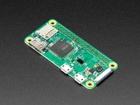
If you didn't think that the Raspberry Pi Zero could possibly get any better, then boy do we have a pleasant surprise for you! The new Raspberry Pi Zero W offers all the benefits of ...
hushed flax
In research phase: https://hackaday.io/project/167264-wireless-animatronic-pokemon-plushie

Place the ZigZagoon down with its foot on the right spot and it'll come to life.
 sweet plank
Anyone able to give me a hand with using the 9685 servo controller and a raspberry pi? Im trying to follow along with the stuff on the website and im not having much luck
sweet plank
following the tutorial on there i can make an LED lightup no problem, but servo does nothing
primal shell
Which website?
sweet plank
the stuff under learn.adafruit
Sorry i was checking something
been going through this

Adafruit Learning System
Learn how to connect and program the 16-channel 12-bit PWM/Servo Driver with Arduino, Python or CircuitPython
Managed to connect the LED and light it up, but the code gets a bit less well presented when you get to the servo bit and im not sure if im doing something wrong or?
primal shell
How are you powering your servos?
sweet plank
Im using a USB powerbank hooked up to the terminals, it has auto shutoff but i can override it for 20 seconds so It should be sending 5v to the board
trying to think if i have anything better to test with
any bad reason to just plug in 4 AA (assuming i test and make sure voltage isnt too high)
primal shell
Yeah, that should be fine (the 4 AA cells are even mentioned as an option in the "Power for the Servos" section).
sweet plank
ill try that, remove the powerbank as a failure option
primal shell
That's what I like to do, divide and conquer.
sweet plank
on it, shoved some AA in a lego powerbank thingy and ill hook it up in a mo haha
right, got a solid 6.2 ish V but still no motor output
primal shell
Hmm. Are you using Arduino or CircuitPython?
sweet plank
running on a pi
primal shell
Mmm. What library are you using to talk to the PCA9685?
sweet plank
the adafruit one
the bit of tutorial code to control LED worked fine through the pca9685
i suspect the kit command to control the servo isnt working right with the pca9685
i dont get any errors or anything which is making this hard
primal shell
That is making it hard.
sweet plank
i2cdetect says i have something on 50 and 70
40 and 70* sorry
and it works with LED
primal shell
Right, if it's working with the LED, that means you're talking to it.
So either some registers are getting set up wrong, it's controlling a different output than the one you have the servo connected to, or there's some weird wiring issue.
sweet plank
or the board itself is broken
which is always a possibility
i just tried a few servos, none of them work, on different adresses
so i think we can assume its probably not the servos
primal shell
I suppose you could test one by running it directly from the Pi https://learn.adafruit.com/adafruits-raspberry-pi-lesson-8-using-a-servo-motor
But I agree, it's probably not the servo.
sweet plank
it COULD be the board, maybe its not providing power from the terminals or something
the ground seems to be connected
could connect voltage to the v+ pin i suppose....
I just hooked the power to eh v+ pin
and the servos moved
and I nearly had a heart attack
SO faulty terminal apparently, good to know!
sweet plank
thanks, thanks for being a sounding board and giving me some ideas haha
primal shell
Happy to.
 humble glade
Is there any downside to running a 2A nema 17 motor at 1.5A vs buying a 1.5A motor?
primal shell
A little less holding torque than running it at 2A, basically, but it will likely behave similarly at speed, since the current is generally limited by inductance at higher step rates.
A 1.5A motor will likely give about the same performance at 1.5A as a 2A motor will at 1.5A.
humble glade
Alright, thanks. Seems like it'll work just fine for my use case. I'm somewhat stumbling my way into motors and robotics. It wasn't until after purchasing the motors that I realized the DRV8825 drivers should really only operate at 1.5A max.
primal shell
Since I often use whatever I have lying around, I run a lot of things somewhat mismatched. It generally seems to work out for me.
 dawn mulch
HI all, I am a mentor for a young robotics team (grades 8 thru12) and we are planing on building some small robotic projects that can be controlled via BLE or WiFi (iphone or Android using the Adafruit apps). I would like to use an M4 board and program in circuit python, Make Code would be a plus for the beginners. They need to control up to 4 TT motors, 4 servos, a few switches and some neopixels. What would people suggest for boards. Thanks in advance
primal shell
Hmm, while there are several M4 boards and matching motor wings/shields/Crickits, most of the M4 boards don't have BLE or WiFi. However, the Metro M4 Express AirLift does, and would work with a motor shield that would get you pretty close.
 true condor
Using Wi-Fi in CircuitPython on the Metro M4 Express AirLift
https://learn.adafruit.com/adafruit-metro-m4-express-airlift-wifi/internet-connect-2

Adafruit Learning System
Give your project an AirLift with a Metro board with WiFi
dawn mulch
I was looking at that board today. Is WiFi as easy to program as BLE? Any rummers about a Metro M4 with BLE??!
 safe bluff
M4 Feather with Crickit and /or motor wings, plus an Airlift wing also may get you what you want for an M4 Wi-Fi config.
primal shell
There is a Circuit Playground Bluefruit, which could be used with a Crickit to add motor/servo/neopixel functionality, but it uses a totally different CPU.
BLE is a little tricky, so there don't seem to be add-on boards that supply that functionality, so it's generally only available with CPUs that are already BLE-capable. The AirLift boards do offer the ability to add on WiFi to most CPUs.
The only BLE add-on board I'm familiar with offhand is the nRF8001 breakout, which is an older technology board and I'm not sure how well it's supported by M4, CircuitPython, etc. I've used that board in the past, and it was a little frustrating.
true condor
@dawn mulch In my experience, Wi-Fi will be easier. With BLE, you'd need to use the Adafruit Bluefruit LE Connect app for iOS or Android. Or craft your own mobile app. (Non trivial)
With Wi-Fi, a device can log info wirelessly to https://adafruit.io or a local server. Or, you can set a device up as a web server, and visit the device over Wi-Fi, using any phone or desktop browser.
Adafruit IO is the easiest way to get your projects onto the Internet of Things!
 signal canyon
Does anyone know if there a way to track time using an Arduino with out any RTC module? I know that when I use delay() it’s delaying but I would like to post the output in the serial monitor. I only need to use like 5-6 seconds. Thanks!!
 cursive helm
@signal canyon take a look at the millis() function https://www.arduino.cc/reference/en/language/functions/time/millis/
The Arduino programming language Reference, organized into Functions, Variable and Constant, and Structure keywords.
signal canyon
Thanks so much
sweet plank
So I want to measure the voltage on the 3.7v batteries I have with an ADC and my raspberry pi. My plan is to use a voltage divider to break the voltage down low enough for the ADC to read (3.3v) If i use say a 20kand a 10k resistor to send 1.33 ish volts to the ADC would this work? Secondly am i allright o just cut the positive wire on the battery and splice in the output for measuring from there?
 rugged stirrup
@sweet plank I would expect that to work fine. Depending on how long you expect your battery to last you may want to increase the resistors further. A 30k load will use a little over 2.5 mAh per day (which might not be a big deal)
sweet plank
Its no big deal . thanks for the tip though
dawn mulch
Is there a way to have a WiFi gamepad talk directly to a Metro Airlift using Circuit Python or makecode? Thanks
hollow shoal
probably but you'd have to figure out the wifi gamepad's protocol
sweet plank
Anyone passing through who has useful links for programming robot motion, specifically a quadruped, please drop some links
primal shell
I already shared my favorite quadruped locomotion link with you, but here are a couple more:

Bionic quadruped robots received considerable worldwide research attention. For a quadruped robot walking with steady paces on a flat terrain, using a cam drive control mechanism instead of servomotors provides theoretical and practical benefits as it reduces the system weigh...
sweet plank
the sunfounder robot has the same kind of degrees of freedom mine will have when it gets its big boiy legs, could be useful
primal shell
sci-hub is good if you want meaty academic papers without a paywall. For example http://sci-hub.tw/10.1109/ICRA.2011.5979619
(that's a paper on "Running and Turning Control of a Quadruped Robot with
Compliant Legs in Bounding Gait")
sweet plank
I am trying to avoid academic papers if at all possible
though i get the impression building an inverse kinematics model for the robot would be useful
primal shell
Elektor magazine had a good article on inverse kinematics with their whiteboard clock project.
sweet plank
Im sad because i can find a ton of cool looking quadrupeds walking around on youtube. But I have been unable to find the code for any of their walks
I feel its going to be a lot of trial and error
primal shell
The verbiage in the original article seemed reasonably clear as to the conditions required, it seems like the sort of thing that can be figured out without resorting to advanced trig, matrix algebra, or truly complicated models.
It would be nice if you could do a move one leg at a time approach, but you end up with a lot of scrabbling and not much motion. So you're stuck moving several legs at once, trying to make their tips move in a coördinated fashion (generally linear), which is a little complex since each leg has multiple spherical translations to its motion, so it's fairly mathy.
I grabbed Elektor's one-page writeup on inverse kinematics for you (from their "sand clock" project).
 fierce ledge
So i've been learning programming for a while. And i have advanced knowledge when it comes to mechanics and fabrication. And i would like to combine those. But i have no knowledge of circuits or servos etc. Ive only ever worked with hydraulics before.
Got any tips for how i could get started understanding which controllers and electric parts i need? Was thinking about trying to make a small hexapod. Then maybe later make a large one.
I already have a pi zero. But i have no clue what i need to get function calls translated to movement / sensors.
primal shell
I'd suggest buying an inexpensive servo (like https://www.adafruit.com/product/169) to experiment with. They're controlled with a pulse train, so you can use PWM capabilities to run them directly from a Pi. There's a useful writeup here https://www.raspberrypi-spy.co.uk/2018/02/basic-servo-use-with-the-raspberry-pi/
Generally if you're running a lot of servos with a Pi, a servo hat is useful, but to get started, you can wire directly to a PWM GPIO pin (servos only have 3 wires, power, ground, and the control signal).
fierce ledge
Servos work the same way as PWM fans?
primal shell
Not really: PWM fans have their speed controlled by the PWM duty cycle. Servos have their position controlled by the PWM pulse width.
The wiring, however, is the same.
fierce ledge
So it sais those have a torque of 1.6kg. that won't work if i make it out of metal i guess. it would be to heavy to move.
I'll buy one to play around though.
Would love a 3d printer for prototyping, but it's to expensive for hobby projects
primal shell
The inexpensive micro servos are good for small light projects and learning about servos, but yes, you'd want more powerful ones for a more substantial robot.
While there are inexpensive 3D printers out there, they tend to have limitations and need a fair amount of work to get them working reliably. However, there are other options. I do a lot of prototyping in cardboard, then move on to bandsawing luan or having a bureau laser cut parts out of plywood or sheet plastic. There are also 3D printing services.
If you have access to a local hackerspace, they may also have 3D printers, laser cutters, and similar useful tools.
sweet plank
If it helps any, i bought a £115 printer and have added another £50 of stuff to make it not a fire hazard
fierce ledge
plywood is a nice material to work with. we used it at work a few times. but then you need a laser cutter.
not sure there is any spaces like that. but i'll have a look
primal shell
I picked up a tabletop bandsaw at a yard sale for $40: it's great for cutting plywood.
An ordinary saber saw will work too, and doesn't take up as much room. Scroll saws, jigsaws, and coping saws are also possibilities.
true condor
@fierce ledge I love my inexpensive Monoprice Select Mini 3D Printer V2. I got one open box for $99. It's available new for under $200. Build volume is 120mm³. (4.72in³)
https://www.monoprice.com/product?p_id=15365
The World's #1 Selling 3D Printer* Too often, getting a low-cost 3D printer means getting a box of ill-fitted parts with poorly written and incomplete documentation.
Adafruit stocks the Monoprice Inventor II, which has a larger build volume:
https://www.adafruit.com/product/3897

The Monoprice Inventor II 3D Printer Touchscreen with WiFi is a perfect entry-level 3D printer with small footprint and reliable performance. It comes equipped with WiFi so you don't ...
fierce ledge
I'll have a look. but all budget ones i've seen in the past always bad bad results. but maybe a lot have happend these past years. would be cool to have one small enough to have on a desk
primal shell
In my experience, the budget ones can give good results, but need more tweaking/adjustment than the fancier ones. My first printer was a Monoprice Mini Delta, and I ended up doing an assort of modifications on it, and adjusting models/parameters in various ways before printing, but it does make nice prints.
One advantage of having to do all that tweaking is getting a good education on how 3D printing really works, which pays off even if you move to other printers.
sweet plank
Pretty much, the difference is often how much fiddling you have to do
Though my very first printer was an anycubic kossel delta
Came in a box of parts
8 hours with wrench and caliper later and I had a delta printer making pretty amazing prints
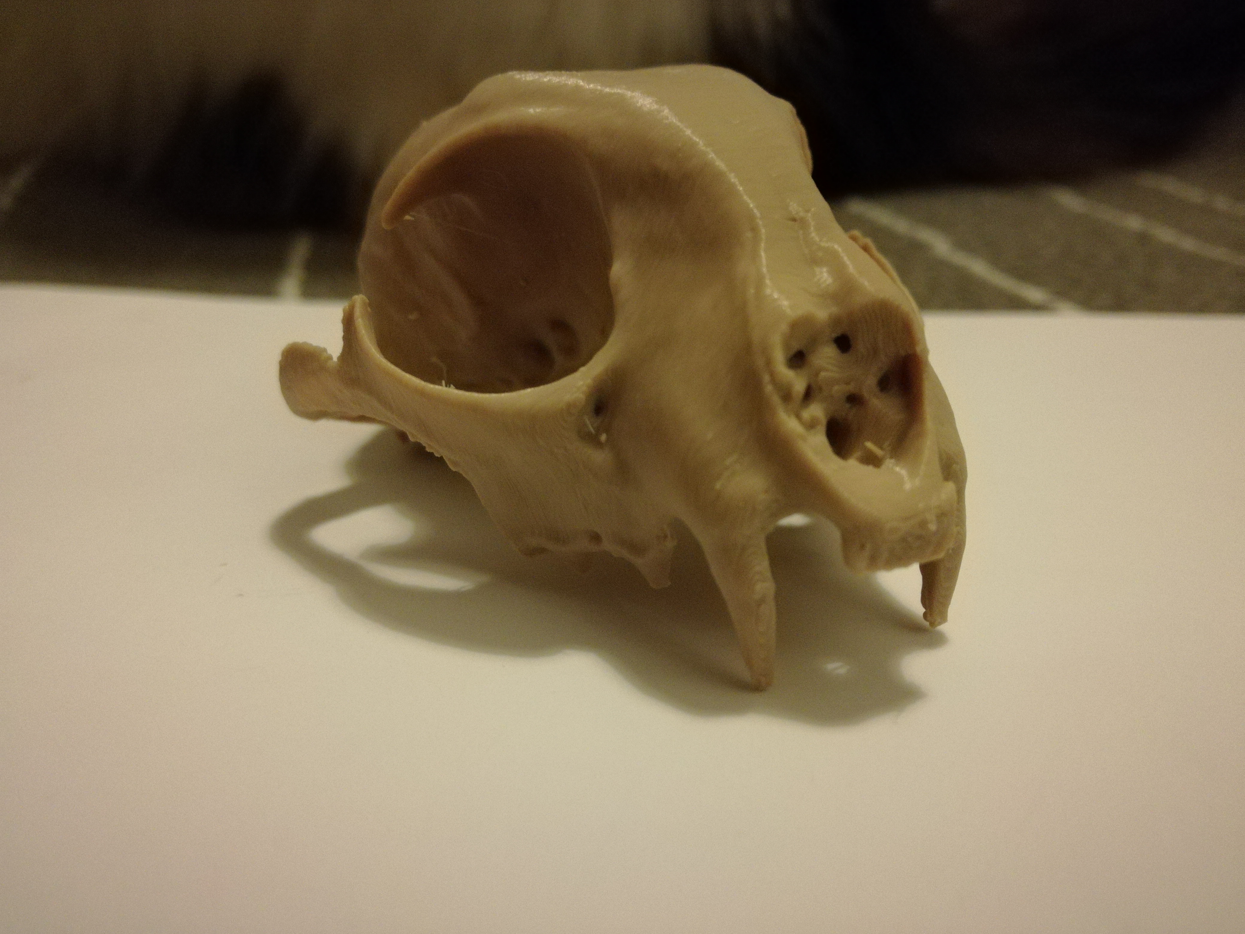
One of the first things I printed
That's a five centimeter long bobcat skull
But as a general rule, all 3d fdm printers are capable of roughly the same detail
It's the speed, accuracy and repeatability that you trade
 shy flower
How is L46 both constant and variable?
primal shell
L46 is not constant.
shy flower
Okay so it's just a typo then?
primal shell
Probably? I didn't write it.
shy flower
I just wanted someone to confirm that they're thinking what I was thinking lol
 dusty mist
I'm having problems with my adafruit-8-channel-pwm-or-servo-featherwing, I've moved from a feather where it was working somewhat, but I moved up to a pi4 when I started testing as I'm more use to them. I've connected a cheap ossilocope to a pwm+gnd; I'm only seeing a Vmax of about 1V that starts every ~90ms, telling the controller to sweeping 0-180 gives me between 5ms and 20ms pulses(still starting 90ms apart). (for that servo connection)ground to v+ shows a steady 4.98V from a 4xAA battery pack Green 5VOK light on(I did have to connect the ground from the battery to the ground of the pi4 before it would see the i2c device). Did I fry/damage my servo controller? Any suggestions for more troubleshooting/fixing?
dusty mist
Nevermind, user error! Lession learned: If you use a featherwing as a breakout board don't forget to power the 3.3v pin aswell
 sonic python
How should I connect 6 ESCs, 6 Brush less motors, an Arduino and a 3S battery?
Quite unsure on the battery part...
sly sand
what repository should i install flask from?
on BeagleBone Black
i tried www.palletsprojects.com/flask
sweet plank
depends n your OS i imagine, does oyurs not have it in the default?
heady spire
Hello,
I am working on a robot with four planetary gear motors from Actobotics. They are strong motors, but that comes with a price - literally. I've plowed through three motor HATs just trying to run them for half a second. The maximum current is 20A, so the normal Adafruit board doesn't work. This is the URL to the motors: https://tinyurl.com/313-rpm-motor
Sorry, accidentally pressed enter, editing now.
After days of searching, I finally found a suitable motor controller: https://www.pololu.com/product/3751
with the library at:
https://github.com/pololu/dual-g2-high-power-motor-driver-rpi/
However, it isn't working with one motor. I have a battery connected, the power light comes on, and there aren't any errors (As long as I remember the syntax [NOT easy with this one!]) I run motors.motor1.MAX_SPEED, and nothing happens except the return of the int 480, which is the value of the constant MAX_SPEED. I've checked all of my connections, and I've switched the wires around a few times. I've rebooted, and I installed the libraries in both Python 2 and Python 3. I've also tested the motor by connecting it directly to the battery, and that worked fine. So, the error is either on the RPi or the board. Please help!
P.S. I would also like to set up Twython-streamer to only listen to one user, is that possible? Or should I just use Discord? I've heard great things about Discord-RPi interfaces.
Thanks,
2231puppy
This add-on board makes it easy to control two high-power DC motors with a Raspberry Pi. Its twin discrete MOSFET H-bridges support a wide 6.5 V to 30 V operating range and are efficient enough to deliver a continuous 18 A without a heat sink. The drivers offer basic cur...

GitHub
Python library for the Pololu Dual G2 High Power Motor Drivers for Raspberry Pi - pololu/dual-g2-high-power-motor-driver-rpi
primal shell
Do you have a voltmeter or oscilloscope? My first guesses are a bad connection or a pin conflict.
heady spire
I do. What should I test?
primal shell
Motor one uses pins 12 (PWM), 24 (direction), and 22 (enable)
Motor two uses pin 13 (PWM), 25 (direction), and 23 (enable)
The enable pins (22 and 23) should read logic "high" (3.3V)
The PWM pins (12 and 13) should read a varying but non-zero voltage when the motors are activated
heady spire
OK, I'll try it out. Thanks!
heady spire
No readings whatsoever. I ran motor 1, and think that the library isn't sending the signals to the GPIOs. I grounded it, and there's still nothing.
primal shell
Weird. You said one motor worked?
heady spire
Sorry, I wasn't being clear. I wrote the code to run motor 1 and executed it. The motor didn't move.
BTW, thank you so much for your help.
I'm pretty sure that it's the code, because I tried a second HAT identical to the first and it didn't run.
primal shell
You can try some simple GPIO code (or even command line GPIO) to set the enable pin and PWM pin high: the motor should turn. If so, your hardware is fine and you can concentrate on the software.
If it doesn't run, verify that the pins are high.
primal shell
Playing with coördinated motion with a somewhat slapped-together 3-joint leg
 hardy pond
nice!
 oblique bane
It's like a desktop claw
true condor
@primal shell Just a bit more refinement and you can make a breakfast robot!
https://www.youtube.com/watch?v=E2evC2xTNWg

I programmed a uArm robot arm to feed me Cheerios for breakfast. And yes: duct tape is an inevitable part of the DIY process. Read my article at Motherboard ...
primal shell
@heady spire and other folks looking to power bigger motors, it looks like Infineon is offering some nice motor control boards in Arduino form factor https://www.elektor.com/catalogsearch/result/?q=infineon
true condor
@primal shell Cute video by Infineon on the IFX007T motor driver shield:
https://www.youtube.com/watch?v=5yQY-CGptBI

https://www.infineon.com/novalithic https://www.infineon.com/shield-for-arduino Watch how easy it is to connect the IFX007T shield to an Arduino and to use i...
primal shell
Um, blink? "Inhabit pin"? The code tries to control all 3 channels, but only one is wired? That's not a very satisfying video, for one that's trying to market to engineering types.
true condor
Yeah, OMG you're right – that's where it falls down. I like the cinematography, but didn't really look at the code.
primal shell
I didn't really care for the cinematography either, the focus was sloppy and the glitchy transitions were distracting.
sonic python
I want to make a project somewhat like this: https://www.youtube.com/watch?v=LmvUkbdXNbM (spherical rolling thingy) with an Arduino. I can imagine I'll need motors, some batteries, but what else? I'm a newbie and can't think of much more things.
(Also, I thought about making it slide with a motor on the center axle to maybe help with the turning, but is that even possible?)
Sorry for asking such a stupid question, but I'm new and not sure on which parts I would need. Thanks.
sweet plank
probably need a motor driver shield or similar
sonic python
Are those a must? I thought they were only optional
sweet plank
arduino can only supply so much current per pin
for a robot thats gonna zoom round, probably gonna need a motor shield, plus it will include a h bridge so you can drive motors both way etc
 frigid perch

Does this guy look familiar? Of course it does! It's our Black, 3-Layer Round Robot Chassis Kit from AdaBox002!This kit gives you everything you need to build the shell of a ...
Does anyone know the gear ratio of the motors used on this bot? Thanks!
I need something with a lot of tourque and those motors can do it if they have a low gear ratio.
What about this robot as well? Thanks! https://www.adafruit.com/product/3216
Unleash your inner Mad Max and make your vehicle dreams a reality with the Mini Red Round Robot Chassis Kit.This kit gives you everything you need to build the shell of a 2-wheel-drive ...
NVM. I think I found good motors on the adfruit website I like better for this bot that I think will work. Thanks!
 dry mural
Hey I'm using this motor for a small feeding machine, so according to the data sheet of the a4988 driver. I should set the resistor to 0,8 volts. The resistors on the pcb say R100, so 0,1 Ohm. Is that right?
frigid perch
The correct number of ohms will vary upon motors and the vref formula. Let me send you a link. @dry mural
 dry mural
@frigid perch Okay thanks for that info. Somehow the potentiometer shows me a range between 1,3 and 4,1v
You know what im doing wrong?
frigid perch
I tune drivers all the time. @dry mural
dry mural
So do I have to set a special pin to high or why does the pot start at 1,2v
Or should I better seletec millivolt on my multimeter?
@frigid perch
frigid perch
You want millivolt. @dry mural
dry mural
I tried but didnt helped 😦
So im also asking myself the Amazon said 4.1V 1A. But the Productnumber says 12V 0,7A
frigid perch
It should be having a power input of 12v. What is your setup? Thanks! @dry mural
frigid perch
Okay.
FYI you will need jumpers on certain pins to enable microstepping and more on your driver. @dry mural
frigid perch
You will need it anyways because otherwise it won't spin.
dry mural
Kk
So yeah the 12V goes to VIN of arduino and Vmot of the driver
The logic of the driver is powered by the 5v of the arduino
frigid perch
Is the problem solved?
dry mural
Idk yet
frigid perch
Okay.
dry mural
I just want to be sure about the calbration first
frigid perch
Okay.
frigid perch
Try .5 amps of current to the motor. Might be better since this is a 1 amp motor supposedly.
dry mural
So yeah it still doesnt let me go under 1.2V
frigid perch
Does it work?
dry mural
With running 1,2V?
frigid perch
Yeah.
dry mural
It doesnt let me go under 1.2V
frigid perch
I would wait for someone else to jump in. Something doesn't seem right and I am probably not the man to help you. Good luck! <@&617066238840930324> Maybe you guys could help?
dry mural
Thx for your help
frigid perch
Np! I have never done exactly what you are trying to do FYI. I normally tune stepper drivvers on my 3D printer main boards lol. Sorry I wasn't much help.
frigid perch
Glad you figured it out!
 foggy zinc
Hi I am currently working on my senior capstone project for college. I am trying to code this servo to move 45 degrees left and 45 degrees right. I have just ordered a servo hat to place onto my raspberry Pi but I am stuck on what code to use for it mainly because this servo can rotate more than 180 degrees. (Very new to coding)
Here are the specs for this specific servo
 brave locust
Servos work on the a pulse. this one "time range" is 600-2400 microseconds. So every if the signal turns on for 600 micro seconds, and then off, it'll turn to 0 degrees. 601 micro seconds turn 1.57 degrees, 602 is 3.14, 700 microseconds is 700. There are libraries available to do the conversions but I sometimes find it easier just to use a map() function in python or c
//0-2826 degrees
//600-2400 uSecs
map(0,2826,600,2400);
and I see now danh helped you in the other chat
foggy zinc
@brave locust Still appreciate the help 🙂 thank you
 left field
Hello, maybe somebody can help me with some questions about stepper motors and using the Stepper Featherwing. Does my power supply have to match the voltage of the stepper motor? In other words, with a 12v stepper do I need to attach 12v to the Motor Power Pins on the board or can I get away with using 5v @ 1-2.1 amps a-la USB? Does the feather stepper board have a boost converter or whatever?
Also, does the board supply power to the feather it's attached to or will it also need additional power via USB or lipo?
I'll continue looking through the guides and documentation to see if I can answer these questions myself as well. It's for an animated costume
primal shell
The steppers will be weaker and more sluggish with lower voltage, but they should operate.
There's no converter on-board, the Feather and stepper motors will each need a separate power supply.
left field
awesome, thank you
brave locust
word of warning when under powering steppers, start at low speeds and accelerate gracefully
primal shell
The achievable top speed will be less as well, as the time it takes for the voltage to overcome the inductance is longer with lower voltage.
High performance systems will often use a higher voltage than the motors' ratings, and have the stepper motor controller adjust the timing dynamically to properly control the current. When it works right, you can get excellent performance out of 12V steppers with a 36V supply without burning the steppers out.
brave locust
As I'm using steppers more and more, do you have a good reference point that goes past the basics of what a stepper motor is?
(specifically so I don't burn out any more h bridges)
primal shell
Blargh, I wish I did.
brave locust
Every tutorial I've found so far has been these are common steps, and these are your coils. It triggers on a positive edge, so theyre super precise. and thats about it
Would they fall under a control systems course?
primal shell
The tutorials I've seen are similar, they gloss over a lot of details, some of which are important.
sweet plank
Im not sure how much detail you need, but that has some
theres some further reading style links at the end too
primal shell
There's also this application note that ST offers, explaining how stepper motors work with an emphasis on driver chips (which, of course, they sell): https://www.st.com/content/ccc/resource/technical/document/application_note/57/c8/7c/c1/0d/91/46/89/CD00003774.pdf/files/CD00003774.pdf/jcr:content/translations/en.CD00003774.pdf
Ed Nisely's blog has a bunch of content on CNC, steppers, drivers, electronics and such, and reflects a lot of good hands-on experience. https://softsolder.com/?s=stepper
left field
i'm just using mine for a slow, steady rotation like 1-2rpm of a piece of plastic weighing like a 45rpm record so I think undervoltage will not be a problem for my particular project
primal shell
Yeah, I expect that will work. You might even be able to share a power supply, which would be convenient.
left field
https://snake56.tumblr.com/post/43266375860 making a sort of plastic/papercraft laughing man mask
primal shell
However, stepper motors make a lot of electrical noise which can cause control circuits to glitch, so I try to avoid doing so.
left field
I have a usb battery pack with 2 outputs and ~6aH charge
primal shell
Worth a try.
left field
if it doesn't work I can like glue 8 AA's in place to hack a 12v power supply
primal shell
I've done that sort of thing for other project (like an electroluminescent Halloween outfit), it works.
sly sand
Hey could I have any pointers for what motor controller I should get for an rc plane? Additionally any good radio?
primal shell
Depends on the sort of motor you're considering. There are DC brushed motors, brushless motors, gasoline motors, and probably some others I'm not thinking of. Futaba makes some first class radios, but they're not cheap.
 grim kayak
Why are many Q-learning scenarios such as this https://www.youtube.com/watch?v=Lt-KLtkDlh8 one using "episodes" where basically if you stay below a standard for too long you reset, rather than letting it continuously try to keep moving? I'm really new so this may be dumb lol

Im making something similar, but so far my code just has a q table that is updated nonstop, and the robot doesn't reset.
What is the benefit or need to reset if it is below satisfactory conditions for too long?
sly sand
What's the cheapest and best motor for fpv plane flying?
primal shell
Cox .049?
oblique bane
Not to be a smart aleck, but that is an engine.
primal shell
I was totally being a smart aleck, as "best" can mean vastly different things to different people.
sly sand
well no lies.
it depends on a million factors
how big is your fpv plane
cuz i can build u a fpv paper plane
i dream of a flying solar wing orbiting my home.
with laser canons and a habbit of wanting skynet to rise
"ok what seems to be the firmware bug?"
"it keeps wanting to enslave humans"
"ok we can fix that"
"hopes' dreams, Deleted"
 brazen tangle
How can I as a complete motor n00b, start with "Dynamixel" (TM) ?
I want to design a 3dof manipulator with 3 dynamixels and Robotis brackets. I know nothing of these. 1- How to choose a part number (guess MX is suitable but I don't know the trade-off conditions) and 2- What MCU should I use to control these? openCM? or some high level SBC like beaglebone?
primal shell
To choose the actuator, you figure out how much torque and speed you need then you can use this chart to find one that's appropriate
You don't need a very powerful MCU, as the Dynamixels are smart. You basically just need one that can send asynchronous serial data at 5V TTL levels.
If you need to do coördinated motion, you'll need to accommodate for that, too. Note also that if your actuators aren't all the same (sometimes you might want a more powerful one for one axis), you'll need to either make sure they can all speak the same protocol (http://emanual.robotis.com/docs/en/popup/faq_protocol_compatibility_table/), or adapt your software to support different protocols to different actuators.
brazen tangle
@primal shell Thanks. Why Torque is reported as kglength instead of Newtonlength (since tau = r * F) ?
primal shell
I can only guess, as I didn't produce that data, but my thinking is that Newtons are generally used to measure work, and the chart shows stall torque, and a stalled actuator is producing a force but not moving, so is not doing any work.
Vaguely analogous as to why jet engines are rated in thrust instead of horsepower..
brazen tangle
@primal shell You know what my problem is? I want to attach this 3dof manipulator to a quad. The problem is, deriving the specs and all lower-bounds and upper-bounds means actually solving the problem of control in simulation (which I've not done yet). I'm wondering if it is possible to choose kinda conservative specs for motors to be able to solve this problem with some guess-formulas (like thrust of quad should be double of its payload)
I'm looking for these linear derived-out-of-experienceguess-formulas to choose my motors for 3dof robt
primal shell
Quad as in quadbike? Or quadcopter? Or quadruped robot? I can imagine any of these scenarios, but the answers vary widely depending on what you actually have in mind.
brazen tangle
quadrotor
I've been thinking if weight of 3dof manipulator is low w.r.t quad, I could get away with PID
primal shell
Hmm, a quadrotor isn't a very mechanically stiff platform, so I doubt you could exert much force from one, and weight is presumably going to be an important parameter, so my first instinct is to simply choose the lightest actuators available, they'll probably still be stronger than the platform itself.
brazen tangle
@primal shell About the lift capacity of quadrotor, should I consider worst-case thrust for each motor? (like lowest voltage regime, 50% throttle)?
primal shell
Looking at the specs, the AX-12W seems like the lightest one. Weirdly, on the individual pages, the stall torque is given in Nm (1.5nM at 12V for the AX-12A)
Alas, I don't have any useful knowledge or experience in sizing quadrotor motors.
brazen tangle
@primal shell Do these Dynamixels have some kind of start up guide or n00b application note (not datasheet)
other parts like sensors like ADXL345 or Arduinos do have guides all over the net
primal shell
I'm not very familiar with them (I generally use ordinary servos or Mechaduino), but a quick web search brings up http://www.robotis.com/download/doc/Dynamixel_pro/Dynamixel-Pro Quick Start_en.pdf
Searches for "getting started dynamixel" and "dynamixel tutorial" bring up lots of likely pages
brazen tangle
@primal shell And I think this chart you mentioned does not contain all of their products..
I was looking for a parameter search web service like Octopart in their site
primal shell
There's this one: http://en.robotis.com/service/selection_guide.php

I found that (and a bunch of other possibly useful links) here http://www.robotis.us/technical-resource-center/
brazen tangle
Is there a specific channel to ask SBC (beaglebone) related questions?
Beaglebone blue comes with built-in Li-Po charger. Can I use it as the main MCU for controlling all 3 Dyanmixel servos of a 3dof arm? Problem is MX series needs ~12 V and 2 cell Li-Po outputs 7.4 V. How can I feed the motors?
Is an external DC-DC convertor necessary?
primal shell
Does the built in charger even support 2S?
brazen tangle
@primal shell BB blue does
primal shell
Oh, neat. You could use a boost converter, but I'm guessing the Dynamixels draw a fair amount of current, which would be even more current at a lower voltage, which implies a largish battery, which might be beyond the capabilities of the built-in charger.
brazen tangle
@primal shell fair point. I should look into max current source of built in LiPo, yeah?
primal shell
A lot of the built-in chargers offer 100mA or so charge current, which would result in a pretty slow charge for a larger battery.
brazen tangle
But Blue is specifically designed for robotics applications. I think it may be on 4A range
primal shell
Ah, that's a lot more appropriate. You might be in good shape then, just need to choose a boost converter with sufficient current capability to run the actuators (or you could use smaller individual converters for each actuator).
This regulator is nearly capable of running three MX series actuators at stall torque at once. https://www.pololu.com/product/2895
 fierce gyro
I'm looking at https://www.adafruit.com/product/3216 -- can I really run it with the motor featherwing and a 3.7V LiPo battery? Some of the material about the featherwing indicates that a minimum 5V is required...?
Unleash your inner Mad Max and make your vehicle dreams a reality with the Mini Red Round Robot Chassis Kit.This kit gives you everything you need to build the shell of a 2-wheel-drive ...
I'd rather use the lipo than 4 disposable batteries if it will work okay
primal shell
It does say 5V is required, but you might be able to run it from 3.7V, however if it's shared with the CPU there might be power supply noise/sag issues (depending on your motors and LiPo). You could, of course, use two LiPo cells in series to get 7.4V to run your motors, instead of using disposable ones.
What I've done in my project is use 3 lithium cells in series for 11.1V, and then using that to run the motors, and then a UBEC to get 5V from the same supply, which I feed to the Vusb lead to power an Arduino or Feather.
fierce gyro
@primal shell thanks, that helps
 wraith flame
Hi! I'm working with a kit that has a AA-style casing, requiring two 14500 3.7V Li-ion (it's the OpenCat Nybble kit). That's an odd battery size that I don't have, but I've got a lot of Adafruit 3.7v Lipos around. If I take a battery like the 3.7v/2000mAh, wire a female JST into the power terminals of the board, then plug my Adafruit battery in, should this be equivalent? Any advice on how to tell if I'm thinking properly about the replacement is appreciated. Thanks!
true condor
@wraith flame Looking at the Nybble docs and forum, they talk about >3.5A current required. I'd look at the datasheets for the batteries you plan to use. The datasheet for one of Adafruit's flat LiIon 2000mAh batteries (prod id 2011) says the max discharge is 1 C5A, which I believe is 2A max. For the cylindrical 2200mAh battery (prod id 1781), max discharge is 2.0 C, or 4400mA, which sounds closer to your needs. However, I wouldn't put two random LiPo/LiIon batteries in series or parallel. Multi-cell Li battery packs are built from carefully matched individual cells, to avoid fires or explosions. Here's a forum post about that, where Adafruit recommends against using Li batteries in series or parallel:
https://forums.adafruit.com/viewtopic.php?f=8&t=152515&p=752904#p752904
I also see this in the Adafruit Learning System:
https://learn.adafruit.com/li-ion-and-lipoly-batteries/multi-battery-packs

Adafruit Learning System
All about the power packs that propel your projects!
I'd lean towards using the 14500 batteries that Nybble recommends, but I'm still concerned about this design, and their suggestion of using batteries without protection circuitry. If this were my Nybble, I'd seriously consider adapting to use high-quality, 7.4V RC vehicle batteries, designed for moderately high current draw. Perhaps one like this:
https://hobbyking.com/en_us/turnigy-battery-4000mah-2s-30c-lipo-pack-xt-60.html

Hobbyking
Choose high performance batteries for RC planes, racing drones and remote control cars. Buy battery packs online at HobbyKing for 24hr technical support.
wraith flame
Thanks @true condor. I tried the single adafruit 3.7v/2000mAh (this product ttps://www.adafruit.com/product/2011), but the servos acted oddly, so I'm assuming I've got some sort of mismatched battery. I've ordered both 14500's and a 7.4v Lipo. I'm still unclear what I need to match up when trying to figure my power needs. I did read the concerns regarding placing batteries in serial, but that's definitely not what I wanted to do. The battery box that comes with the device is for 2 x 14500 3.7V Li-ion batteries. The 14500s seem tough to come by, esp. unprotected, as recommended. There seems to be some sort of jumper I can change on the board so I can use 7.4v Lipos. You mention the max discharge above, which I didn't see as part of the battery requirement, but sounds like the flat Adafruit battery is below what these 14500 3.7's provide. What should I be looking for to see if I can find some other battery that would provide appropriate power, but that I can wire in so I don't have to wait for the weird form factor of the 14500? Also - huge thanks on your kind help. You've been really super answering all of my questions these past few weeks & I greatly appreciate it. I feel like I'm learning a lot, but there's still SO much I don't know. Cheers!
primal shell
The battery world is immense, pretty much anything you need is available somewhere.
wraith flame
I'm charging 14500 Li-ion batteries for the first time. Am using this charger: https://www.amazon.com/dp/B07428G1G2/ref=cm_sw_em_r_mt_dp_U_Si0XDbTGH8CM4 Put four in at the default setting, listed as 5.00 mA. Batteries got very hot, so I pulled them out before they were done. Image of the batteries I picked up at my local electronics shop are below. Is heat during charging normal? Is there a special setting I should be using? Or did I somehow choose the wrong batteries? Related question: Do folks store their Li-ion / Lipos in a special safety bag? If so, is there any protocol - how many you can store in a bag, etc.? Thanks, just don't want to burn down the house 🙂
 steady wren
@wraith flame Warm is normal, very hot is not. Some good info here if you skip down to the "Carefully does it " header. Sound like deeply discharged batteries should be charged slowly at first, "pre-conditioned," for just this reason. https://www.digikey.com/en/articles/techzone/2016/sep/a-designer-guide-fast-lithium-ion-battery-charging
wraith flame
Well.... looks like these aren't rechargeable batteries, so I suppose that's why things got so hot. Ugh. I really hope I don't burn the house down.
steady wren
Oh yeah, that might matter too! 😮
They look pretty nifty though. https://en.globtek.com/lithium-thionyl-chloride-li-socl2-batteries/
GlobTek, Inc.
sly sand
Depends on your prior experiences.
In general, I ask myself if this is something I'd have to tell the fireman about, as they entered the home, it ablaze.
If it is, it doesn't belong inside the structure at all, when not in use.
So like a 5 gallon jug of kerosene, or a camping sized bottle of liquid propane -- get stored outside the building.
(which for most people means storage is possible only in the warm months, well above freezing, overnight)
steady wren
Retailer's product page: https://dantona.com/comp-6-saft
Shop for COMP-6-SAFT Batteries now at Dantona Industries, inc. A leading supplier of industrial and consumer batteries, chargers, and battery packs.
sly sand
Here's some vocabulary to work with wrt storage and hazards:
https://extension2.missouri.edu/wm6005
LP (liquid propane) is a good model: store outdoors and away from heat spark flame source of ignition &c.
🔻 THIS ONE seems to be quite good: 🔻
https://ehrs.upenn.edu/sites/default/files/2017-12/Lithium Battery Safety Program 2017-1.pdf
quote /The most important safety consideration for lithium-ion and lithium-polymer batteries is to treat the battery as if it will ignite at any time/
They mentioned sand twice as a smothering agent.
Not really sure how you're supposed to approach close enough to use it. ;) Says type ABC extinguisher is effective. Then they take that back, and say it is not effective. ;)
So, 4.1.4 says to use bags provided by a reputable vendor.
Apparently, the bags are real, and not a sales pitch thing.
quote 4.5.1.2 Other simple but effective emergency isolation containers are ceramic pots or
a cinderblock placed with the cavities facing up. /endquote
Sounds like the ammo box culture is real, as well.
wraith flame
Well, this upped my safety concerns. Ordered a bat safe box (https://www.bat-safe.com/), dry chem fire extinguisher, and some bags. Seems wise to be more mindful of risks, especially since I'm such an electrical n00b. Thx for all the recs.
Also working on adding the 7.4v 1500mAh 35c. Project has a jumper for this kind of power, but the battery I have uses a Dean / T connector. Any thoughts on best practice from going from the Dean connector to pins that can screw into a terminal block? Am thinking I'd take a Dean female to JST, then trim the JST off, solder it to header pins, shrink up the ends nice & good so the wires don't have anything that will touch. This way I don't mess with any wires on the battery + simply have a chord I've rigged up as an adapter. Does that seem like a good strategy?
dawn mulch
Hi All,
I would like to know it I can use the Adafruit Feather nRF52840 Express
PRODUCT ID: 4062 with the Adafruit Motor/Stepper/Servo Shield for Arduino v2 Kit - v2.3
PRODUCT ID: 1438? I know I could use a set of feather motor and servo wings but I already have sever of the 1438 motor shields.
If I can, I am assuming the following:
Connections that need to be made between boards:
- Ground for common ground
- SDA and SCL pins for IC2 communication. Do I need to add 10K pull-up resistors to 3.3V like the ones built into the wings or does the shield also have them?)
- 3 volt pin to supply power to the logic chips
Power:
- nRF52840 powered by USB or liPo battery
- Shield board powered by 5-12volts thru power connections (number removed)
Programing:
Using Mu editor v1.0.2 with CircuitPython 4.x or 5.x. on an iMac OS 10.12.6
I am assuming I would use the same code as I would use if I were using the feather motor wing and/or feather servo wing
Additionally, could I use this same setup with other Adafruit M0, M4 boards or with the CPX, or the CPX BLE? I have several projects built around the Arduino Uno and I would like to upgrade them to M0 or M4 boards.
Thanks in advance
Tim
 viral pagoda
I'm wanting to use multiple servos that are able to record movements. What type of servos would you suggest and what power supply? This type of thing can be done using Arduino for the code/control, correct?
primal shell
@dawn mulch I think that would work
@viral pagoda You can use these analog feedback servos to record movements https://www.adafruit.com/product/1404
viral pagoda
@primal shell thanks!
 surreal flame
Maybe a bit of a vague question
But how come electronics are suddenly becoming so accessible for even non engineers to use?
sly sand
Basically a cultural shift.
People like LadyAda decided to make it accessible to everyone.
A different mindset.
Manufacturers began supporting that effort (to make money of course).
Parallax had some stuff, early and even put it in Radio Shack stores.
I don't know when exactly Arduino came along, but in retrospect I'm pretty sure they impacted our subculture substantially with regard to getting this stuff into the hands of educators.
Probably in the 2005-2010 (years) time frame; I haven't looked it up. I was in 8051 world and ignored most everything else. ;)
 dry prawn
3d printing and cosplay becoming normal have helped it along too. Once you 3d print something or make a costume you suddenly have a desire to make it blink and make noises
surreal flame
And in that sense you can see the DIY movement is very anti-consumerism
Also open software like
The most advanced open source autopilot for use by both professionals and hobbyist. Supports multi-copters, planes, rovers, boats, helicopters, antenna trackers and even submarines.
Stuff like that would have cost 10-20k 15 years ago
Was Parallax one of the first ones?
primal shell
I think Arduino became popular, because they vanquished three of the usual barriers to entry at once (leveraging flash-based MCUs that could program themselves). 1) no external programming hardware needed. 2) easy to install, multi-platform integrated IDE. 3) Reasonably easy to learn language and libraries with nice obvious entry points (setup(), loop()) and calls to do things (digitalRead(), digitalWrite(), etc.).
That, coupled with the rise of the internet, helpful vendors  , open source, a global economy, and exposure to computers in general all conspired to make electronics less mysterious and more accessible than it had been since at least the 1920s.
sly sand
In the 1960's and early 1970's it was still difficult to get the average person to imagine a new use for 'electronics' that they had not been previously exposed to. Just for consuming pre-assembled equipment.
The kinds of experiments you could do at home were somewhat limited.
The Forest Mims books were probably representative of what was to be had, if you did have interest (nobody forcing you).
(there were magazines, too)
Around 1975, in Hartford county, Connecticut, there were three parts vendors you could just walk in off the street, and buy from them, retail. Hatry (Hartford) and Heathkit (Avon) both sold Calectro parts.
Competing directly with Radio Shack's parts wall.
So somebody had to be buying that stuff for them to stock it.
viral pagoda
curious what would be the best way to keep a pushrod in a servo horn from pivoting in the hole? Trying to have a stiff "arm" of straight wire swing on the servo. Would epoxy be the best way to go about it?
dry prawn
hmm, "best" would probably be to 3d print a custom servo horn with your arm built in. Next up, is there a second hole in the horn you can hook the wire through? (and small pilers to bend the wire)
primal shell
I've had good luck 3D printing shapes with a servo horn recess in them to extend the arm. Actually printing the horn itself seemed tricky, which is why I attacked it this way.
viral pagoda
@dry prawn yeah I think the simplest would be to hook the wire into one end and have it go under and up through another hole...may need to be drilled so it could fit
@primal shell good idea! so the 3-d printed arm is made to just press fit over the standard horn shape? the central hole in it will allow the screw to pass through to screw everything together correct?
primal shell
That was the original idea, but I've actually moved on from that, so now the hole is larger and the hub of the horn fits in it, with the screw still going through the whole stack.
viral pagoda
nice very good idea
also, I'm using a power bank to power the project right now (10,000 mAh) and it keeps automatically shutting off within a minute or two with no activity. any way to ensure it stays on? maybe I'm using the wrong power source?
I turn it on, the microcontroller lights up and I
I'm able to do everything just fine but if I leave it be, the whole thing turns off and I have to manually turn the bank back on
primal shell
Many of those power banks only stay on if there's a certain load applied. There are a few ways to attack that. One is to find a power bank that stays on. Another is to hack the power bank so it stays on (only for those with experience with modifying lithium battery circuitry). The last is to apply an additional load to keep the power bank activated. All of these (especially the last) tend to make the power bank run down faster.
viral pagoda
is there any particular bank that you'd recommend that would stay on?
primal shell
Alas, I don't know of one offhand. Bigclive did a bunch of teardowns and tests on youtube and that's one of the features he's interested in. There is the issue that what was available last month could be different from what's available this month.
viral pagoda
Or I wonder if there is something I could stick in the other USB output on the bank that would draw juuuust enough power to keep it on?
primal shell
Right, that's the third option I outlined. There are USB adjustable loads that might suit, but really all you need is a USB connector and a resistor with the right resistance and dissipation.
Alternatively, you could just use a separate powerboost circuit instead of the built-in one.
viral pagoda
Would the USB connector and resistor combo be the simplest method?
primal shell
For example, you could use this battery https://www.adafruit.com/product/353 with something like this https://www.adafruit.com/product/2030

Need a massive battery for your project? This lithium ion pack is made of 3 balanced 2200mAh cells for a total of 6600mA capacity! The cells are connected in parallel and spot-welded to a ...

PowerBoost is the perfect power supply for your power-hungry portable project! This little DC/DC boost converter module can run from 1.8V batteries or higher, and convert that voltage to ...
The resistor is probably the simplest (if most wasteful) option.
viral pagoda
If this helps, I would only need to have the circuit "live" and on standby ready to activate for approx 1hr time
primal shell
Oh, that's not too bad then.
viral pagoda
So a usb connector with a resistor soldered to it?
primal shell
You might be able to find a USB LED flashlight that draws the right amount of current, which would provide a handy "it's on" indication as well (unless this is a more stealthy deployment)
viral pagoda
would the light have to be turned on in order for this to work?
or would I just have to plug it into the bank to start charging it
primal shell
Yes, however many USB LED flashlights are always-on (just plug it in to use it)
I'm thinking of the kind without their own power supply
viral pagoda
maybe I could just cover the light as I want it to have no visible light output
primal shell
If you don't want the light output, you might as well just use a resistor. If it's tricky to solder directly to a USB connector, it's easy enough to cut up a USB cable, find the right wires in it, and solder the resistor to those.
viral pagoda
@primal shell
so just plug in a USB cable to the available port and solder a resistor to it or are you saying to mod my existing USB cable that is powering my project by adding a resistor along the power line?
@primal shell what type of resistor would you recommend and to what wires would it need to be soldered to?
primal shell
I was guessing your power bank had more than one port, so I was thinking just use a sacrificial USB cable for the resistor load.
You'd want to solder it to the V+ and V- leads (not D+ or D-).
The value of the resistor depends on how much current draw your power bank requires to stay activated.
viral pagoda
ah good point
will prob have to contact the manufacturer for that info
so just cut a separate cable and expose V+ and V-, then connect one side of resistor to + and other to -?
primal shell
Probably easier to try it and see. You'd need some sort of resistor assortment (or substitution/decade box) or adjustable load.
Yes, to hooking the resistor from V+ to V-
viral pagoda
got it ok! Just sent an email to the manufacturer! Hopefully they will provide some insight
would the greater the resistance = the greater the chance of it sensing that there is a "load"?
primal shell
Other way around: more resistance = less current, less resistance = more current. Current is what (probably) causes it to detect a load and stay powered, so if it doesn't stay on, you need less resistance.
viral pagoda
hope this doesn't sound stupid but I'm using a USB cable that's been cut with a resistor bridging the V+ and V-. The cable is not connected to any device that actually uses power...it's just a cut cable..is this correct?
primal shell
Right. I'd probably cut the cable completely in two and just use one end.
Alternatively, you could use a breakout like https://www.adafruit.com/product/1833 or a separate plug like https://www.adafruit.com/product/1387 or a USB power cable like https://www.adafruit.com/product/2697

Simple but effective - this breakout board has a USB Micro-B connector, with all 5 pins broken out. Great for pairing with a microcontroller with USB support, or adding USB 5V power to a ...

Make your own USB connections without slicing apart a USB cable and soldering those thin wires inside. These DIY "USB shells" are available in USB A plug, micro B, mini B and USB A ...

There's two standard ways to power electronics - USB or 5.5mm/2.1mm DC barrel jack. This or that! With this USB to 2.1mm Male Barrel Jack Cable, you can now power 5V DC powered ...
viral pagoda
primal shell
Yes, that's what I had in mind.
viral pagoda
so far I've used a 1K, 330 and a 1K to bridge and none have worked
primal shell
Let's see, Ohm's law says that 330Ω across 5V will draw about 15mA.
viral pagoda
hmmm what about soldering a little LED to the + and -?
primal shell
No, LEDs need a current limiting resistor. If you have another 330Ω resistor, you could parallel two of them for a 30mA load.
viral pagoda
yeah I've got a few of them
lemme try that real quick
nope
didn't work
I have a little USB fan that I could plug in I guess if all else fails lol
or maybe I just need more 330 resistors?
primal shell
If, for example, that particular power bank took 100mA to recognize a load and stay on, it would take 7 330Ω resistors in parallel.
The USB fan is a good idea, give that a try.
viral pagoda
yep USB fan works for sure and I will also try adding more resistors
viral pagoda
@primal shell gee no wonder why it wasn't working! Wired resistors in SERIES rather than PARALLEL! Switched everything to parallel and it seems like just (3) of the 330Ω resistors are making it work!
primal shell
Oh yeah, series is going the opposite way (less current) than you want. 
viral pagoda
@primal shell really appreciate the help on this! another electronics problem solved!
one last thing: I noticed that I unplugged everything and plugged it back in and power bank immediately shut off. I had left extra red and black wire exposed after the parallel resistors just in case I needed more and noticed they had crossed over and were touching. Was that causing everything to shut off due to a short?
primal shell
Probably so: most decent quality power banks have protection circuitry so they'll shut down on overload.
viral pagoda
ok good to know...I better clip that extra off then!
true condor
@viral pagoda There is one USB battery pack I've found (from Voltaic Systems) that you can put into always on mode:
https://www.amazon.com/gp/product/B00CLNI49S/ref=ppx_yo_dt_b_search_asin_title?ie=UTF8&psc=1
I kinda wish @abstract ice carried these, since they match up so well to low-power projects – in always on mode, they won't just shut off after a few minutes – and Adafruit already carries other Voltaic Systems products.
Additionally, Paul Stoffregen of Teensy fame published this PCB design that tricks your garden-variety USB battery pack into staying on:
https://oshpark.com/shared_projects/Da8m8oAz
This would also be an interesting as an @abstract ice breakout, to complement the PowerBoost series.
viral pagoda
@true condor perfect!
this will save me so much grief
as the method of stacking resistors in parallel works most of the time but seems to be flaky
 fallen lagoon
Have you looked at the https://www.sparkfun.com/products/15204 - Low Current Lithium Ion Battery Pack - 2.5Ah (USB) - While similar power banks are typically designed to power off automatically at lower currents, this battery pack will continue to operate if your device is drawing a mere 20mA and over!

We've taken the classic, portable, rechargeable lithium ion battery pack and tweaked the design to make it amenable to low current applications.
 twilit tusk
Hi all! I’m currently designing a 60 lb combat robot and I am trying to figure out my controller. I would be using an RC receiver but I am wondering how I would control my drive motors from it.
primal shell
Most receivers provide PWM servo signals as outputs. Some motor controllers accept this as input.
wraith flame
Newbie servo question. I've noticed when setting servo angles, my servos are rotating short of the .angle property setting in my code. Is there a way to tinker with the precision on the microservo depicted (sg51r)? If I only need 90 degrees, then I can just up the value to compensate, but if I needed 180 degrees, I can't exceed 180 on my servo setting without getting an angle out of range error. Here's a video showing the servo moving from 0 to 90 to 180 https://youtu.be/8tL4Gf6chPM and here is the gist of the CircuitPython beta 5 code I'm using on a Circuit Playground Bluefruit: https://gist.github.com/gallaugher/7ada10b85892cae071a831604685aca2 Thanks for advice!
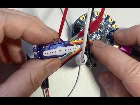

Gist
short servo demo in CircuitPython for CircuitPlayground Bluefruit - code.py
cursive helm
@wraith flame - you can adjust the servo min/max pulse as described in this guide https://learn.adafruit.com/circuitpython-essentials/circuitpython-servo (at the end of the page) be carful not to push beyond the limits of your servo.

from the sg51r product page Note that the default servo pulse widths (usually 1ms to 2ms) may not give you a full 180 degrees of motion. In that case, check if you can set your servo controller to custom pulse lengths and try 0.75ms to 2.25ms. You can try shorter/longer pulses but be aware that if you go too far you could break your servo!
wraith flame
Thanks, @cursive helm. I'm not sure I quite understand what the ranges do. In the REPL when working with a servo object I've set up, I changed my_servo.min_pulse = 0.75 and my_servo.max_pulse = 2.25, then did rotations with my_servo.angle = 0 and my_servo.angle = 90 and didn't notice a difference. I then tried my_servo.max_pulse = 2.0 and my_servo.angle = 90, expecting this would change where the 90 degree value rested and I'd see slight movement, but I see no movement. Tried my_servo.max_pulse = 2.5, then my_servo.angle = 90. Still no movement. If I set angle back to 0 and then angle to 90 again, it seems to go to the same location as it did before I tweaked max_pulse. I've even tried my_servo.max_pulse = 3.0, but I'm not noticing any difference even with this larger number. I see larger values used in the readthedocs at: https://circuitpython.readthedocs.io/projects/motor/en/latest/api.html#module-adafruit_motor.servo, but smaller values here: https://learn.adafruit.com/circuitpython-essentials/circuitpython-servo. I also tried getting out then back into the REPL, reconfiguring a Servo object as my_servo with this code I'd been using: pwm = pulseio.PWMOut(board.A1, duty_cycle=2 ** 15, frequency = 50) and my_servo = servo.Servo(pwm), but then when I try to print(my_servo.min_pulse) or print(my_servo.max_pulse), I get an AttributeError: AttributeError: 'Servo' object has no attribute 'min_pulse'. Curiously I can manipulate this property via my_servo.min_pulse = 0.75, then the print works. Same with max_pulse. So sorry I'm not quite getting this. Thanks for your help!
cursive helm
I'll set one up and run some tests here. It'll take a bit to dig out the parts.
cursive helm
hmmm -- contrary to the example the settings are in microseconds, not milliseconds -- I fI use
servo = adafruit_motor.servo.Servo(pwm, min_pulse = 1000, max_pulse = 2000)
then I see a clear difference when I set it to my_servo =0 or 180 then the default of 750,2250

GitHub
Helpers for controlling PWM based motors and servos - adafruit/Adafruit_CircuitPython_Motor
>>> import board
>>> import pulseio
>>> from adafruit_motor import servo
>>>
>>> # create a PWMOut object on Pin A2.
>>> pwm = pulseio.PWMOut(board.A2, duty_cycle=2 ** 15, frequency=50)
>>>
>>> # Create a servo object, my_servo.
>>> my_servo = servo.Servo(pwm)
>>> my_servo.angle = 0
>>> my_servo.angle = 180
>>> my_servo = servo.Servo(pwm,min_pulse  = 1000, max_pulse = 2000)
>>> my_servo.angle = 180
>>> my_servo.angle = 0
>>> my_servo.angle = 180
>>> my_servo.angle = 0
>>> my_servo = servo.Servo(pwm,min_pulse  = 750, max_pulse = 2250)
>>> my_servo.angle = 0
>>>
you cannt set it using my_serve.min_pulse -- that does not exist
you can use my_servo.set_pulse_width_range(min_pulse = 1000, max_pulse = 2000) https://github.com/adafruit/Adafruit_CircuitPython_Motor/blob/master/adafruit_motor/servo.py#L47
GitHub
Helpers for controlling PWM based motors and servos - adafruit/Adafruit_CircuitPython_Motor
If I just do this : I see the position for 0 move significantly ```>>> my_servo.set_pulse_width_range(min_pulse = 1000, max_pulse = 2000)
my_servo.angle = 0
my_servo = servo.Servo(pwm,min_pulse = 750, max_pulse = 2250)
my_servo.angle = 0
@wraith flame I hope that all makes sense -- If not, let me know ...
wraith flame
Thanks - hugely helpful & much appreciated. I've worked with my sub-micro servo & kept moving the parameters out to the edges until I arrived at: my_servo = servo.Servo(pwm, min_pulse = 573, max_pulse = 2383). It seems that if I decrease min_pulse any more or increase max_pulse any more, the servo buzzes a bit, which I suppose means I've exceeded the 180 degrees. The result isn't quite a 180 degree arm swing. Should I just assume this is the best I'll do with an SG51R? And is the approach of increasing / decreasing values until just before the buzz is noticed, a good approach, or am I doing something wrong. Again - much thanks for your kind guidance on this.
cursive helm
@wraith flame Sounds like you are getting it where you want it. I am no expert on servos. You are now about as knowledgable as me! My SG51Rs also do not have full 180 degree motion. Good luck!
wraith flame
@cursive helm Super - this was wonderful advice. And it's good to know you are experiencing the same not-quite 180 degree rotation. Wishing you a great day!
 broken terrace
Hi all. I have a UBEC rated for a "2S-6S" LIPO that I'm using to power a Raspberry Pi and Crickit hat as part of a robotics project. I give it 7.5v from my bench power supply, it's drawing .27a. The thing is, when powered on it emits a high pitched whine that's very annoying - it's near the edge of my audible range. Is this normal for a UBEC or indicative of a problem with the part or my usage?
primal shell
I would expect them to operate out of the audio range, but it's possible this one doesn't, or there's some sort of subharmonic oscillation for some reason (interaction with the bench supply, maybe?) that's causing the audible noise. I think the first thing I'd try would be powering it from a different voltage and see if the problem changes. Then I'd try a different (battery?) supply. Then I'd try a different UBEC.
viral pagoda
I have a 12v gear box motor (worm gear) and would like to somehow convert it into a linear actuator. Is there a way to do this? Would like it to extend a 12 inch shaft out all the way when a button is pressed and retract it when button is released. Pretty sure there is a way to do this. I would assume 3d printed parts?
primal shell
If the worm gear is long enough, you just have to add a travelling nut like https://www.pololu.com/product/2688

This copper alloy traveling nut is intended for use with Tr8×8(P2) threaded rods and features a mounting flange with four holes threaded for M3 screws. This is the same nut that is included with our stepper motors with lead screw.
viral pagoda
@primal shell that is the type of motor I have. Not sure how the traveling nut will help.
primal shell
I had guessed (incorrectly) that the worm gear was external. You'd need to add a threaded shaft, or some other mechanism (bellcrank, belt, or tension band) to get linear motion.
viral pagoda
and what would be the best way to have this motor start turning one way, then reverse direction when I want it to?
I have a DC motor that I'm trying to get to turn one way, then reverse direction when I want it to. Is this done using an Arduino? I'd like one push button to be pushed then the motor revolves to a certain position then stops. When I release the button, the motor revolves the opposite direction and stops at a certain point
primal shell
You reverse a brushed DC motor by reversing the power supply. This can be done electronically with a circuit arrangement known as an "H bridge", electromechanically with a relay, or manually with a reversing switch or by switching the wires.
viral pagoda
Is there a way then to set up an H-Bridge with an Arduino controlling the revolutions and the time that it takes?
primal shell
Yes, that's a common arrangement.
The easiest way (if your motor runs on 4.5 - 13.5V and draws 1.2A or less) is with a motor shield like https://www.adafruit.com/product/1438

The original Adafruit Motorshield kit is one of our most beloved kits, which is why we decided to make something even better. We have upgraded the shield kit to make the bestest, easiest way ...
The cheapest easy way (if your motor runs on 600mA or less) is with an H-bridge chip like https://www.adafruit.com/product/807

Run four solenoids, two DC motors or one bi-polar or uni-polar stepper with up to 600mA per channel using the L293D. These are perhaps better known as "the drivers in our Adafruit ...
 severe perch
I need to make an assembly for collapseable. Does adafruit have parts I need for collapseable effect?
 hoary nexus
Hello y'all
I was wondering what would be a good choice for a like
a 4 channel relay board for either a feather or a ras pi
kinda deciding which board to use based on what the availability of the relay board is
thinking of running 5V through it
primal shell
Relays may be overkill for routing 5V signals.
There's a Particle 4-relay board. These 2-relay boards can be used with pretty much any controller https://www.pololu.com/product/2485
This quad relay board is also nice https://www.sparkfun.com/products/15102

The SparkFun Qwiic Quad Relay is a unique power accessory board, used for switching 4 high powered devices from your Arduino or microcontroller using I2C.
hoary nexus
alright thx!
hoary nexus
I just like relay boards cuz it seems neater and easier than like
Getting transistors or mossfets and like
Doing that stuff
Also if it goes wrong, wouldn't want to fry my pi
primal shell
Relays are safe and don't care about ground loops, voltage offsets, polarity, or any of that stuff.
hoary nexus
sounds like a good time
sonic python
So I have this school competition project for a line follower robot, but it's our first time building something like this, so I'd like to use good parts for this. What MCU, motors, and IR sensors would be better suited for the job? Budget is not a problem. Thanks if anyone helps
 sharp lark
@sonic python what size constraints are you working in?
I use GoBilda and REV, but then again, I'm working with 18 inch robots, so it would be pretty bulky for a simple line follower
check servocity.com for motors, and custom 3dp is always viable for structure if you are experienced with CAD and printing
sonic python
Piece wise it's kind of a problem because there's only one site on our country that gives receipts, and we need them... As for sizes, the common thing you see on YouTube and such. I don't have exact numbers but it's not that big
(the chassis will be 3d printed)
sharp lark
what site is it?
sonic python

PTRobotics
Compre componentes eletrônicos a preços baixos. Representamos fabricantes mundiais em Portugal.
It's got some stuff from Sparkfun and Adafruit, so it isn't that bad
(it works with search terms in English by the way)
sharp lark

PTRobotics
GA12-N20 Mini DC Gear Motor 6V 30rpm Voltagem:6V Material: Metal Modelo: n20 Velocidade de rotação: 30RPM
this looks promising if you want small

PTRobotics
Rubber Wheel w/ Micro DC Geared Motor 3-6V Description: Plastic Robot Wheel Tire With DC3-6v Gear Motor For Smart Car Arduino Features: Magnetic interference...
otherwise this is probably the go-to motor for hobby robotics
as for control systems, a raspberry pi or arduino works
sonic python
That's pretty different from our initial idea
We initially thought of this: https://www.ptrobotics.com/motores-dc/4960-velleman-mot3n-dc-motor-12vdc-180ma-11500rpm-6-14vdc.html

PTRobotics
Velleman MOT3N - DC Motor 12Vdc 180mA 11500rpm (6-14Vdc) Standard Brushed DC Motor Specs operating voltage: 6-14V nominal: 12V no load:speed: 11500rpm curre...
sharp lark
you will probably want a gearbox on that
otherwise it won't have enough torque and be uncontrollable
sonic python
We really got into something knowing nothing about it...
Didn't even know we needed a gearbox ..
How do we use them? Our objective was to honestly make this car as fast as possible
sharp lark
for something like line following, speed is not always the most important
you don't want to accidentally overshoot the line
sonic python
Well, yeah, but this is a competition to see what robot is the fastest
sharp lark
also, just the bare motor might not be powerful enough to move the bot, depending on weight
sonic python
If we could take it slow just to make sure we made it, this wouldn't be a challenge
What would we need extra then?
sharp lark
what do you mean by extra? wheels? sensors?
sonic python
"just the bare motor might not be powerful enough"
What would we need more? I got a bit lost
sharp lark
a gearbox like the yellow one I posted above would allow it to have more torque
by power I meant torque

Hello Guys, In this tutorial, I am going to show you how to make a DIY Arduino Line Follower Car. So let's get started :) Subscribe It's Free https://bit.ly/...
sonic python
Thanks a lot
dawn mulch
@viral pagoda @primal shell if you are looking for a great source for robotic parts try ServoCity (https://www.servocity.com/ ) or there sister site GoBilda (https://www.gobilda.com/). They engineer and manufacture most of there own structural products and have everything from motors and servos to structural components to linear motion components. Good prices, excellent service, and lots of build tutorials. I’ve purchased a lot of products from this company and have never been disappointed.
primal shell
Thanks for the pointers!
primal shell
@dawn mulch I finally figured out the difference between those sites! Gobilda for metric, Servocity for inch! 🤪
sharp lark
#GoBildaorgoHome
GoBilda is by far the best build system I have ever worked with, and their customer service is unrivaled
This robot is almost all GoBilda, and it works really well. GoBilda is all bearing based, so the motion is really smooth, and the tolerances are really precise
ionic quartz
That seems cheaty
sharp lark
What do you mean by “cheaty”
ionic quartz
A ready to go kit!
sly sand
@ionic quartz great word you got, there.
.. like a Betty Crocker cake mix grenade ...
.. just pull the pin to release it
ionic quartz
I love that comparative
sly sand
Hitchens said to avoid every cliche ;)
sharp lark
That robot is not from a kit
I have spent months designing, doing cad, and building it
primal shell
Nice! Your project and praise for GoBilda just resulted in me ordering some assorted hardware from them.
sharp lark
You will not be disappointed!
GoBilda does sell a couple of strafer kits, with or without mecanum wheels, but it looks a lot different
primal shell
The one kit I was looking at was out of stock, so (aside from a screws+nuts kit) I bought a pile of individual parts.
sonic python
https://www.youtube.com/watch?v=mBZU9S0kZJw what are the weird wheels being used in this robot?
Thanks


This robot uses something similar too: https://www.youtube.com/watch?v=EF8ds1fm7x8&t=82s
https://www.facebook.com/Maslerbotics Hola les presentamos un nuevo avance de nuestro robot seguidor de linea -TAQUIÓN- Masler Robotics. Entre algunas mejora...
 native minnow
Any recommendations on getting started with robotics?
sharp lark
Start simple
Once you build something easy, you can start doing more challenging robots
But if you try to do too much at the beginning, you’ll burn yourself out and you won’t want to continue
sharp lark
@native minnow what kind of robot do you want to make and what is your end goal? What is your budget, and what are your constraints?
native minnow
not sure was just trying to see what was out there, I watched my little brother's robotics competition the other day and it looked pretty neat! Was hoping for nothing too expensive but wanted something that I could at least tinker with a bit or get a feel for
and see if it is something I want to invest more into
true condor
@native minnow One inexpensive, and brand new option is the Pi Supply Bit:Buggy, which has just been added at Adafruit:
https://www.adafruit.com/product/4442
The Pi Supply Bit:Buggy Car is a small and cute DIY smart car based around the BBC micro:bit. It's a simple but well-designed lil robot car and is a great way to take the ...
true condor
Have you done any coding, like with Arduino, CircuitPython, or MakeCode, @native minnow ?
true condor
@native minnow micro:bit supports both MakeCode and Arduino.
primal shell
And MicroPython
primal shell
@sharp lark You're right, I'm not disappointed with Gobilda. My original plan for the camera mount didn't work, but I was able to simply take it apart, rearrange the bits, and get a setup that works.
sharp lark
Looks great! I’m glad it worked for you!
 azure lagoon
does anyone know whether most hobby servos are brushless or not? asking for a friend...
primal shell
I suspect most of them are ordinary brushed DC motors, they're cheap and reliable and don't need complex control electronics.
This page https://learn.adafruit.com/adafruit-motor-selection-guide states, inter alia, "Inside, an RC servo typically consists of a brushed DC motor with a gear train and a built-in H-Bridge motor driver."
Clear bodied servos make it easy to tell: this Hitec HS-35HD lets you see there are only two wires (red and blue) going to the motor, showing that it's an ordinary brushed DC motor.
 spiral coyote
alright guys i need help with 2 big projects
i need all the tips and feedback i can get
is anyone familiar with controlling a reaction wheel in an inverted pendulum situation?
sly sand
I think big buildings have those up high. ;) Bicycle rider is inverted pendulum.
spiral coyote
well, i need to build something like this :
https://www.youtube.com/watch?v=AvGUuuq7DOE
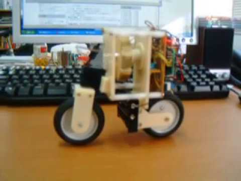
Bicycle robot that balances using reaction wheel pendulum
kinda wanna know the equation behind this actually
im asking here to know if there are experienced people regarding this topic
so that i can know what to watch for, what to count, etc
steady wren
@spiral coyote I haven't quite done that, and maybe someone who has will chime in here. Once upon a time I did write a Segway simulation in Python, using wheel torque as the variable under control to keep the thing balanced--whereas here I guess it's steering angle.
The lesson I took away from it was that it made sense for it to be a common engineering lab challenge. It needed proportional-integral-derivative control with non-zero values for each of three scaling factors to work, but it was pretty easy to tune because it wasn't super touchy about what those values were--they needed to be somewhere in the ballpark basically. Good luck with it!
 prime tundra
Hi all if i wanted to make an animatronic flower that closed and bloomed would i need a servo for each petal or is there a system where i could control movement of multiple petals with one servo and a combination off other parts? I am trying to build this into a prop for a costume so the smaller the form factorbthe better.
sharp lark
@prime tundra it should be possible with linkages and just one servo
spiral coyote
heyo guys
has anyone ever worked with this driver?

The TB6612FNG Motor Driver can control up to two DC motors at a constant current of 1.2A (3.2A peak). Two input signals (IN1 and IN2) can be used to contro
if so, can anyone tell me how's the overall performance is?
second, about this equipment
i understand how it works, im just curious if i can hook up both GND pins
 toxic fog
Well, both GND pins are connected on the board
spiral coyote
huh? really?
hmmm
in the hookup guide, the ground is separated
where 1 ground is connected to the signal source and one ground is connected to the signal output
sooo uhm
is it safe if i were to connect all ground to one single node?
i currently have an STM32, an MPU6050, that driver chip and the bidirectional logic level converter
would it be safe if i were to connect all of them into one single node?
toxic fog
Ground is supposed to be one common node of all digital circuits, so yes
spiral coyote
alright thanks
toxic fog
Also if you connect two nodes with a wire you get single node
spiral coyote
yeah i know
another question
when there are multiple ground nodes on a chip, is it safe to connect them all into one?
even if there is a chance that it has already been connected?
sorry for the probably stupid question
just don't want my chips to be fried
just don't want my chips to be fried
because im basically handling multiple voltages, i need 9-11 volts to power the motor through the driver chip, i need 3.3 volts and 5 volts for the bidirectional logic level converter. I'm kinda scared when connecting all the power sources, all my chips would be fried
toxic fog
You have to connect all grounds together, because voltage is relative (it has to have a reference potencial -> GND)
toxic fog
Yes, otherwise it wouldnt be able to control the motor driver
spiral coyote
okay okay
i hope this won't fry my circuits
wait so, what would happen if i were to connect the grounds with a soldering line beneath my board and connect a ground with a jumper cable up top
it won't short right?
toxic fog
Just dont connect the positive of 9-11V to any pin of the STM32 and it should be fine
spiral coyote
Right, another question
How do you power an STM32 blue pill from an external power source?
sly sand
zero ohms in parallel with zero ohms is .. zero ohms.
1/Rtotal = 1/R1 + 1/R2 + 1/R3 .. 1/Rn Resistance in parallel.
Connecting the grounds via multiple (very short) paths is equivalent to using a single stranded wire, with parallel individual conductors (The analogy would be more clear if each strand were coated with insulation, as with transformer or other magnet wire).
In that case you would strip insulation off the ends, solder them to bond them, only at the ends, and you'd have the equivalent circuit (several near-zero ohm paths in parallel).
A standard USART to USART connection takes three wires between the two microcontrollers (that have USARTS in them):
TX RX GND for a total of three wires.
That the third wire GND is necessary, is the model for most other interconnections you'll come across. It's considered a 'reference' as someone said, above.
toxic fog
@spiral coyote you can connect 5V to the 5V pin, or if you already have 3.3V source, then connect it to 3V3 pin (the Blue Pill has a weak regulator, so it is better external)
 sterile silo
Has anyone started working with a Sphero RVR? or combining a Sphero RVR with Adafruit products? @exotic onyx or anyone
spiral coyote
@toxic fog thanks
 sacred briar
Hello all, I am new to this chat. I have a question on Adafruit's LSM9DS1 chip.
I want to implement sensor fusion on it, but so far, I haven't found a compatible library for it. I have tried the sensor fusion libraries on @exotic onyx page but it is developed for the LSM9DS0 chip and I can't make it work, I've also tried Kris Wieners code without success.
If this is not the right channel to ask these questions please let me know. Thank you very much!!
sterile silo
Lol!!! Meet our newest robot friend. Just arrived
 urban wren
They're great! Here's what I've done with mine. https://youtu.be/oQxAFZWZkcg

This is a Sphero RVR project to recognize and chase the kitten. It uses a Raspberry Pi on the RVR, then a custom-soldered Adafruit Proto-Pi hat, and then a Pimorini Pan/Tilt Hat with an Adafruit pan/tilt mast. On the mast are a Pi Camera, a MaxBotix ultrasonic rangefinder, an...
spiral coyote
hey guys, i have a question
does an I2C device like an MPU6050 need pullup resistors?
spiral coyote
my device can't detect my MPU at all
toxic fog
If you use the GY-521 module, there are already pullup resistors, so you dont need to add any.
toxic fog
But what board is it on?
spiral coyote
ooh, yeah, right, GY521
okay
but why can't my board detect my sensor?
i've checked the wiring, it's all fine a dandy
i did however powered it with 5 volts, but from my experience it works fine despite the operating voltage
toxic fog
The Vcc sould be 5V, because there is a regulator to 3.3V
 faint beacon
Use an I2C detector to make sure it's on the address you think it's on
faint beacon
there are many possible causes. Bad device sitting on the I2C bus, SDA/SCL backwards, wrong pullup resistors, wrong Vcc
toxic fog
Are using it with the STM32?
faint beacon
also possible I2C frequency too high (although the MPU6050 should handle up to 1Mhz)
spiral coyote
yes
@toxic fog
im using it with an STM32-duino
darn it works yesterday, why not now?
nothing burnt, nothing is short
no smoke, nothing
checked the connections with a multimeter, it's all fine
any ideas?
toxic fog
What pins are you using?
spiral coyote
well, i tried usign PB7 and PB6
and then i tried PB8 and PB9
then PB11 and PB10
none seems to work
i checked my connections with an arduino and my arduino can detect the MPU just fine
then something is probably wrong with my stm
maybe?
@toxic fog any thoughts?
dang it
connecting it directly doesn't work
toxic fog
The pins should be SCL -> PB8 and SDA -> PB9
spiral coyote
i did
it didn't work
wait
'''
I2C Scanner
Scanning...
Unknown error at address 0x01
Unknown error at address 0x02
Unknown error at address 0x03
Unknown error at address 0x04
Unknown error at address 0x05
Unknown error at address 0x06
.
.
.
No I2C devices found
it showed this error now
im now confused
dang it
faint beacon
you can try my I2C detector - it can use bit banging to talk to I2C devices on any GPIO Pins
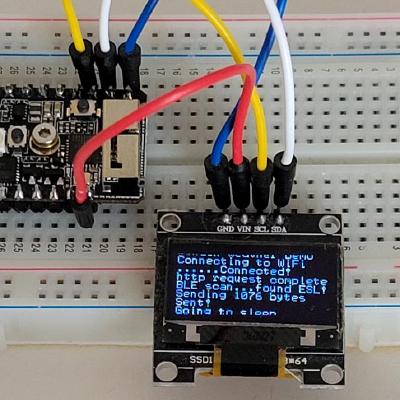
GitHub
A software I2C implementation to run on any GPIO pins on any system - bitbank2/BitBang_I2C
it's in the Arduino Library manager
pass it the Arduino pin numbers
spiral coyote
but i don't need an I2C scanner, i already have a code for that
faint beacon
not true
mine works on ALL pins
it will verify if you're having a problem with the Wire library, your wiring, or something else
spiral coyote
@faint beacon so i just plug it wherever i want it?
or do i have to specify which pins are which?
faint beacon
use whichever pins you want for SDA and SCL, and tell it in the init function which ones you used (PIN numbers, not PORT)
spiral coyote
so i just change the -1?
to any pin numbers?
right, thanks, it worked
and now it's detected
right, now how do i specify which pins to use in a different code?
@faint beacon
faint beacon
if you've detected your devices, you can use my i2C code to read and write to them
the MPU6050 is pretty simple to initialize and read its registers
spiral coyote
ehehe, can you give an example?
faint beacon
take a look at my ss_oled library. It makes use of the BitBang_I2C library
GitHub
Simple and small library to control 1-bpp OLED displays (Linux + Arduino) - bitbank2/ss_oled
spiral coyote
all your examples don't use the bitbang_I2C library
or at least there are no include BitBang_I2C.h commands
faint beacon
The I2C_Detector example shows how to use it
there isn't a whole lot to working with I2C except reading and writing registers
spiral coyote
uhm
there's only I2CScan command
can you just tell me the basic commands?
I2CRead(uint8_t u8Address, uint8_t *pu8Data, int iLength);
I2CReadRegister(uint8_t iAddr, uint8_t u8Register, uint8_t *pData, int iLen);
I2CWrite(uint8_t iAddr, uint8_t *pData, int iLen);
these ones to be exact
faint beacon
that's it
faint beacon
I think I've given you enough info on this topic @spiral coyote. If you're unfamiliar with I2C communication and talking to the MPU6050, then it's a good opportunity to learn more about both. The example code in my I2CDetector sketch shows how to use all of the different functions. From this point on, I would be doing your project for you and I don't have time to do that.
spiral coyote
@faint beacon alright, can you at least tell me what format do i have to write the addresses?
and the data of course
and as for unfamiliar with I2C, all i have ever done is use the wire command and using I2C manually using assembly so your code is new to me
faint beacon
The address format is the one used by most I2C functions -> The upper 7 bits. For example, OLED displays are typically on 0x3c and 0x3d (not 0x78 / 0x7a)
spiral coyote
uhm
well uh, like this?
cus certainly im not doing it right
or do i have to put it as variables?
abd your I2CDetector sketch only shows how to use I2C scan and I2C init
there are no I2C read or I2C write
which is why i am confused
@faint beacon
faint beacon
if you look at the library source code you'll see how to use the functions
the error above is that you're passing the variable type along with the parameters
It's not reasonable for me to teach you how to program. I'm happy to answer any technical question when you've tried to write some code and encountered a problem.
spiral coyote
@faint beacon i still don't get it
i entered a uint8_t for the address but that error still pops up
and i don't understand how your I2CWrite works
why does it asks for I2C address, and then register address, and then data length? where do i put my data to write onto the device?
spiral coyote
or can anyone help me understand the code?
i don't understand anything, even reading the library doesn't help
not to mention that i am new to the uint data type
so i don't know how that works too, i only use the wire command and it works fine
an example, a hint, anything would do
primal shell
The unit data type is intended to be a portable way to specify a specific kind of storage. In that case, an 8 bit unsigned quantity. Basically a byte.
*uint
spiral coyote
okay uh
this is still wrong somehow
Wire.beginTransmission(i2caddress);
Wire.write(0x6b);
Wire.write(8);
Wire.endTransmission();
i just wanted to replicate this using the bitbang code
with the i2caddress being 0x68
primal shell
Should be straightforward enough
primal shell
What is different?
spiral coyote
i have no idea
i don't know how to use it
does it writes instantly, do i have to redirect the program to a certain register first with a read command and then use the write protocol or can i write instantly?
primal shell
That's I2C protocol details, it shouldn't matter whether it's biting or not
spiral coyote
well, i can't upload it because of the error
primal shell
*bitbang
spiral coyote
I2CWrite(uint8_t iAddr, uint8_t *pData, int iLen);
like for example that command
i only see iAddress, is that the i2c address? register address?
primal shell
What error?
spiral coyote
invalid type argument of unary '*' (have 'int')
primal shell
Looks like the other library has a different signature
spiral coyote
or this : invalid conversion from 'int' to 'uint8_t*' {aka 'unsigned char*'} [-fpermissive]
when doing this : I2CRead(0x68, 0x6B, 8);
from this : I2CRead(uint8_t iAddr, uint8_t *pData, int iLen);
primal shell
First August is probably the address, second is a Pointer to the data bytes, third is likely the number of bytes
spiral coyote
well, how do i enter the pointer then?
do i use a * ?
because i don't understand what use of the pointer here
primal shell
You'll have to define an array and put the bytes into it
primal shell
You don't that much C?
spiral coyote
i really need an example
yeah
i don't use arrays very often
especially in arduino
primal shell
You might be better off finding a bit bang library that works more like your original code then
spiral coyote
i don't know which one
so far this is probably one of the codes that can actually detect my MPU6050
because i can specify which pins are used
primal shell
Normally I would just type in an example but I'm on vacation on my phone and typing source code on a phone is a pain
There are resources out there explaining C arrays if you want to stick with that library
spiral coyote
are u kidding me?
i need to manually insert the data?
byte per byte?
can't i just write the direct code -_-
darn
right @primal shell help with this as well
I2CWrite(uint8_t iAddr, uint8_t *pData, int iLen);
so this is an I2Cwrite command
and i don't know where i put the value of the data i want to write onto the device
primal shell
You put it into an array
spiral coyote
wait wait
hmm
darn
does this mean that iAddress is not the device address but already the register address?
orrrr
ugggh, i don't understand how this works
primal shell
You might want to read up on I2C protocol
spiral coyote
all i was taught about i2c is that i need to specify the device address, and then 1 bit to define whether to read or write the device, and then an ACK, and then the register address i want to read or write, and then an ACK or NACK
i've always been doing it like that
manually
primal shell
It's the same via a library, you just have to express it differently
spiral coyote
so when reading that write command, i don't know where to put where
that's what im trying to figure out
is the iAddress the device address at the first protocol or the register address?
primal shell
I think the first arguments is the device address
spiral coyote
and then from what i have figured out is that *pData is the data i want to read or write onto
primal shell
Yes
spiral coyote
but if iAddr is already device address and *pData is the data to specify the register, then where do i put the data i want to write with?
or do i have to use this command ?
I2CReadRegister(uint8_t iAddr, uint8_t u8Register, uint8_t *pData, int iLen);
so far this has the device address, the device register address, and the data
but it says I2CReadRegister
oh wait
humm, might experiment more
uggh, i really need an example from @/bitbank
okay @faint beacon here is what i have so far :
#include <BitBang_I2C.h>
#define SDA_PIN PB7
#define SCL_PIN PB6

uint8_t dataaddress[8] = {0,0,0,0,1,0,0,0};
uint8_t xvalue[8];

void setup() {
  Serial.begin(9600);
  I2CInit(SDA_PIN, SCL_PIN, 100000L);
  I2CReadRegister(0x68, 0x6b, dataaddress, 8);
  delay(100);
  // put your setup code here, to run once:

}

void loop() {
  int hooray = I2CReadRegister(0x69, 0x3b, xvalue, 8);
  Serial.println(hooray);

  // put your main code here, to run repeatedly:

}
is this in the correct format or do i have to use I2CWrite to send a data to set my MPU6050 to the correct power options in void setup?
primal shell
You do have arrays set up there
You may want to use something like b0001000 for binary values if that's what that is
faint beacon
hi
PB6 on AVR should be specified as 0xB6
why are you predefining data in your array, only to immediately overwrite it?
When you write to an I2C device, usually the first data byte specifies the register to write it to, but not always
spiral coyote
because i have no idea what im doing, im just glad i know the formats
now tell me, how do you write data onto the MPU6050 exactly using your code?
faint beacon
one sec.. I'll get you my MPU6050 functions...
int IMUReadBoth(int *accel, int *gyro)
{
uint8_t ucTemp[16];
int x, y, z;
uint8_t start_reg, len;

#ifdef MPU6050
  start_reg = 0x3b;
  len = 14;
#else
  start_reg = 0x22;
  len = 12;
#endif

  x = I2CReadRegister(IMU_ADDR, start_reg, ucTemp, len);
  if (x > 0)
  {
#ifdef MPU6050
    x = (ucTemp[0] << 8) + ucTemp[1];
    y = (ucTemp[2] << 8) + ucTemp[3];
    z = (ucTemp[4] << 8) + ucTemp[5];
#else // LSM6DS3
    x = (ucTemp[7] << 8) + ucTemp[6];
    y = (ucTemp[9] << 8) + ucTemp[8];
    z = (ucTemp[11] << 8) + ucTemp[10];
#endif
#ifndef __AVR__
    if (x > 32767) x -= 65536; // two's compliment
    if (y > 32767) y -= 65536;
    if (z > 32767) z -= 65536;
#endif
    accel[0] = x;
    accel[1] = y;
//    if (z < 0) // upside down
//      z = 0-z;
    accel[2] = z;
#ifdef MPU6050
    x = (ucTemp[8] << 8) + ucTemp[9];
    y = (ucTemp[10] << 8) + ucTemp[11];
    z = (ucTemp[12] << 8) + ucTemp[13];
#else
    x = (ucTemp[1] << 8) + ucTemp[0];
    y = (ucTemp[3] << 8) + ucTemp[2];
    z = (ucTemp[5] << 8) + ucTemp[4];
#endif
#ifndef __AVR__
    if (x > 32767) x -= 65536; // two's compliment
    if (y > 32767) y -= 65536;
    if (z > 32767) z -= 65536;
#endif
    gyro[0] = x;
    gyro[1] = y;
    gyro[2] = z;
    return 0;
  }
  return -1;
} /* IMUReadBoth() */
#endif```l8r
spiral coyote
how do i even implement this thing?
im not working with avr, im working with an stm32
faint beacon
then you need to pass the Arduino PIN numbers, not "PB6"
 tribal magnet
is it common to add decoupling caps to reduce unwanted hardware interrupts?
I've got an errant stepper wired to a stepper driver that seems to be causing all sorts of unwanted hardware interrupts when running
 distant light
Using the servo wing, is there a command to de-power the servo? I’d like to turn it “off” when I don’t need it, then power it on only when movement it necessary
 undone basin
@distant light Looking at the servo FeatherWing schematic: +5v is directly connected to the servos' power pin. Without additional circuitry, there's no way to "de-power" the bank of servos.
primal shell
@tribal magnet you might want decoupling for both power and signal leads. You may want resistive or inductive decoupling as well
urban wren
@spare patrol , @clear mantle and I were chatting about the Sphero RVR SDK porting. I'm going to be working on it more diligently because Scott suggested there would be wider interest, rather than just "curiousity." I understand that asyncio is a bit off in the future, so I'm going to start with the observer code. I'm not sure what hardware to use, but I'll probably start with a Feather M4 Express (very familiar with it from High Power Rocket work) with an OLED FeatherWing for feedback. Once I get the observer SDK working I'll probably write a communications protocol so we can use an ESP32 to talk to a control program (haven't thought that through much.) Anyway, I'm open to suggestions, requests, and ideas!
 spare patrol
You might want to look at the MicroBit code. It might be even easier to adapt. I would start with anything with an M4/NRF52 proc and UART. Feather M4 should be fine. Even a CP Bluefruit would probably be good.
urban wren
Ok, cool. My first goal is "make it work." Then I'll test with multiple devices and see what kind of control interface we can use.
primal shell
High power rocketry? I wonder how many gees a M4 can withstand
urban wren
@primal shell I'm not sure. The problem was the flight controller code wouldn't fit in a Feather M4 memory. I'm actually considering building a custom PCB with all the features, and a lot of extra memory.
primal shell
That sounds like a good project. You might be able to use FRAM