#help-with-radio
1 messages · Page 13 of 1
 primal warren
 hexed raft
thanks!
so basicaly it's one chip as a main part, an what I need more is life support guts around it?
primal warren
If you just want a modulator, often the quickest and cheapest way to get one is to scavenge one out of discarded electronics (VCR, video game, captioning adapter, digital broadcast adapter, etc.: anything that can send a signal to a TV).
Here's one description of the process http://thekeywordgeek.blogspot.com/2015/04/an-inexpensive-video-rf-modulator.html
hexed raft
I have a gut feeling that I'm talking to the author of that description xD thanks
primal warren
Nope, I found it with a brief search, but yeah, that's how I get my modulators: just co-opt an idle VCR or just rip the parts I want out of a discarded one.
You could buy one in a nice enclosure like https://www.ebay.com/itm/Mini-RF-Modulator-Audio-Video-RCA-Output-to-F-Type-Coaxial-Signal-Converter but you don't have to.
hexed raft
Raspberry pi should have some kind of ready made transmitter that works right out of it's analog video output, no?
Oh what's that, lemelook
Error - page is dead
primal warren
It's "baseband" video, so it can connect to a video monitor or a video modulator to make it into an RF signal.
Ramsey Electronics used to offer a nice little modulator kit, but they got shut down by the US Government
hexed raft
wow lol
 slender current
@glad sierra no plans for sdr + circuitpython
@nimble depot just ran across puck.js code you did 🙂
 nimble depot
Oh, awesome, @slender current . What's the context? Anything I can help with?
Demo of that code:
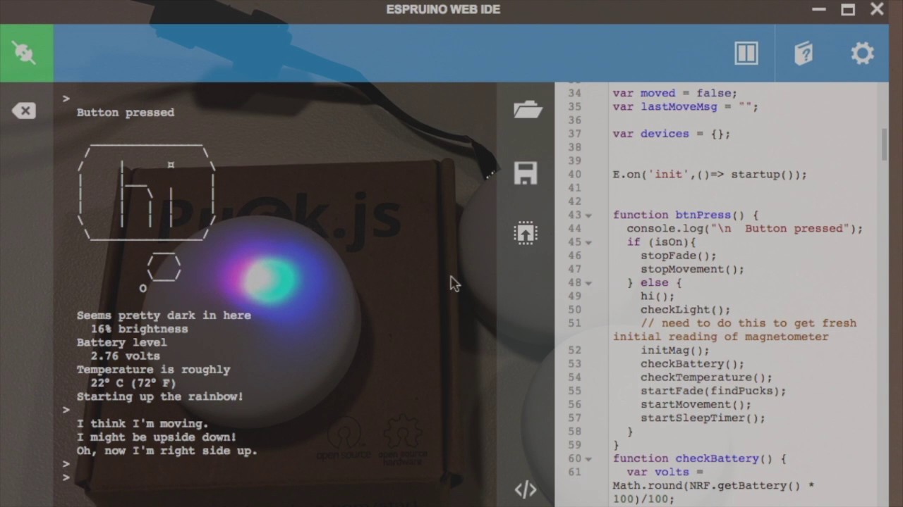
Hello, Puck demonstrates many of the built-in features of Puck.js. Like Arduino, you can use Puck.js to build IoT devices. While you code Arduino in C++, Puc...
slender current
@nimble depot I was just experimenting with other code over ble options. was bummed I had to use the nordic app to update the firmware
and getting into the bootloader was tough without a reset button
nimble depot
Getting into the Puck.js bootloader, you mean?
There's some discussion here:
low battery can cause DFU issues:
http://forum.espruino.com/conversations/303247/
rationale for DFU process:
http://forum.espruino.com/conversations/332775/
http://forum.espruino.com/conversations/334779/
nimble depot
Kind of amazing what Gordon Williams got working on that platform – especially the REPL interacting with a running, saved program, all over BLE.
nimble depot
@slender current Found this iOS (Swift) DFU library. There are also iOS Obj-C, and Android versions. The ReadMe also mentions cross-platform React Native and Flutter libraries. (But maybe y'all are already doing something like that in the Bluefruit LE Connect app?)
slender current
@nimble depot which dfu library? I'm planning on doing react native for my editor prototype
nimble depot
@slender current How did I not paste that in?! Silly me.

GitHub
OTA DFU Library for Mac and iOS, compatible with nRF5x SoCs - NordicSemiconductor/IOS-Pods-DFU-Library
And here's a React Native implementation:

GitHub
Nordic Device Firmware Update for React Native. Contribute to Pilloxa/react-native-nordic-dfu development by creating an account on GitHub.
I've used neither, so caveat emptor
 wraith quiver
Hi, I have this college project I’m working on, its a little rc car sensor platform thingy. And my idea was to use packet radio to communicate back and forth with it using a programme called direwolf. Has anyone ever done something like this that could help out - I do have my amateur licence if that helps in terms if it’s legal
primal warren
While I haven't done anything quite like that, it sounds doable.
 rose sun
Packet seems like quite a bit of overhead to connect to an rc sensor
you're basically doing telemetry and telecontrol, right? Well, you'd need a TNC on both ends. Easy on the computer side, you can use a virtual TNC, but how were you planning on implementing that on the RC side?
wraith quiver
@rose sun I have a virtual TNC on my laptop, with a USB-Link on the robot's side
Build a USB interface for ham radio digital modes for under £10. Home-brew a SignaLink clone using a cheap USB sound card and a handful of junk box parts.
 tiny dust
how do you solve RF problems without using a smith chart
specifically, i want to know how to calculate the amount of electrical length readout (like the outer ring) of an arbitrary impedance
i want to have exact answers/automatable so i don't have to sit there with a compass
never mind, even if i knew that i'd need to solve the nasty R=1 circle equation
primal warren
The equations aren't that tough to solve, but yeah you have to normalize the impedances first.
tiny dust
@primal warren do you know what the "angle" of an arbitrary impedance might be?
primal warren
Depends on its capacitive or inductive characteristics.
A pure resistive impedance has 0° phase shift. A pure inductance has a 90° phase, and a pure capacitance has a -90° phase.
To put it another way, if voltage leads current, it's a positive angle, and if current leads voltage, it's a negative one.
tiny dust
On a Smith chart I mean lols
primal warren
I'm a little unclear on what you mean by "angle" in this case.
 restive fjord
I need a suggestion for a non metallic boom to replace my portable 2m yagi boom. Preferably something i can store the elements inside
restive fjord
I had pvc, but it has warped. I will try acrylic. Need to get the measurements again on the element spacing
primal warren
Ah, it's a strength of materials issue. You may need to go to thicker wall, larger diameter, or a different material (fiberglass)? Larger diameter may be your best bet.
restive fjord
Ok. It was possibly warped due to me keeping it in my car. I didn't think with the position it was stored in with the heat would do that, and yet here I am. I haven't been able to get a true mobile radio installed yet. I have 2 IC-2100's, but I need to get a lip mount for 2m. Rather not have the mag mount on the car, diving through rural roads and clearances and such. Not worried about hf mobile.
One of the icoms i promised to give to my best friend once she gets licensed.
 mint grove
Hey guys, anyone here experimented with the ESP-NOW before? Just wondering where can I get the official library for that because it seems like there are so many different sources
 vocal veldt
@mint grove there's a good tutorial here (https://hackaday.io/project/164132-hello-world-for-esp-now), I'm going to be putting it into the Adafruit IoT newsletter for next month.

I've been using ESP32's in a variety of projects recently, including one in which the ESP32's will be used as a RC link. I plan to use ESP-Now for this, but it took me a much longer time than I'd hoped to get a basic connection working, so I wanted to write up what I did to h...
mint grove
Hi @vocal veldt, thanks for the info. I've seen that tutorial, which sparked my interest in experimenting with the ESP-Now as an alternative to nRF24
But it didnt really say where to get the official library for ESP-NOW
I found this github repository of ESP-NOW from Espressif, but its for ESP-32 only right? I have some esp8266 laying around, planning on using those to experiment on

GitHub
Arduino core for the ESP32. Contribute to espressif/arduino-esp32 development by creating an account on GitHub.
vocal veldt
@mint grove yep thats for 32 only, wont work with 8266
mint grove
well, ok
mint grove
Well, I found Andreas Spiess channel talking about the esp-now on esp8266, so in his code all he did was declare these before the setup() routine, and then you can use all api for esp-now:
#include <ESP8266WiFi.h>
extern "C" {
#include <espnow.h>
}
Here's the video talking about the esp-now, with sample code in the description

Today we will discover a hidden feature to connect two or more ESP32s or ESP8266s directly to each other: ESP-now. It is much faster and more energy efficien...
I tried to compile his code too, it works
restive fjord
If anyone needs a super fast DAC (157 megasamples/sec) for SDR.. for $5 this looks super cool:
https://osmocom.org/projects/osmo-fl2k/wiki
primal warren
That's a creative approach, using a USB-VGA chipset as a generic DAC.
 torn steeple
'The street finds its own uses for things.' -- William Gibson
restive fjord
Where there's a will, there's a way
tiny dust
woa
homework question
Every antenna has one type of plane wave polarization that it cannot
receive at all.
this is apparently a true statement
how is that true
i have a handwavy explanation for it
nvm, i dont
primal warren
Plane wave polarization? Like linear (as opposed to circular) polarization?
restive fjord
ground wave affects local propagation and is generally not too fussy about polarization of the antenna's configuration.
For skywave, it might really matter.
In free space (interplanetary space) might be an interesting question as well.
That said, mobile stations tend to use verticals as a kind of voodoo, at least on the high bands.
The orientation of the antenna is probably quite important to where the main energy lobe goes; if you wanted to bounce off the ionosphere, this could matter.
primal warren
NASA uses circularly polarized antennæ for linearly polarized reception, as a constant polarization loss at any orientation is better than a near total loss at specific orientations.
restive fjord
Sounds like a good solid approach to me. ;)
Handheld ham satellite antennas tend towards the cross polarized type (two dipoles at right angles)
But I've copied DOVE and MIR using a Ringo Ranger II, which is a basic vertical for 2 meter FM work.
primal warren
I've had good results using an ordinary quad loop. One time, I just ran the boom through a couple of ladder rungs to get it tilted to the angle I wanted. For a quick and dirty setup, it worked surprisingly well.
restive fjord
One fun thing to do is run snubbing diodes across the RX antenna terminals .. and run the receiver concurrent with the transmitter, instead of sharing an antenna and a T/R switch. ;)
primal warren
Haven't tried it that way.
restive fjord
I think my Kenwood R599-A was setup that way from the factory.
The thing you don't want is snubbers across the transmitter. I think the T/R circuits in typical era CB's may've incorporated the snubbers inside the radio in such a way that electronic T/R switching passed the RF to the snubbers only on receive (so a loud neighbor signal at a truckstop doesn't blow your your front end on the RX).
tiny dust
i think it's a mathematical curiosity
like, super math stuff
i've heard a pretty fancy way of describing why you can't have a perfect beam with a physically realizable antenna
since the far field integral looks like a fourier transform
you can use stuff about fourier transforms to make some statements
and in the fourier transform if you have a input function with compact support
you can't have an output function with compact support
and vice versa
only one can be compact support
and you can't have an antenna that has a current pattern that doesn't have compact support since it implies an infinitely large antenna geometry
therefore the radiation pattern must have non compact support and side lobes are inevitable
i'm sure it's something similar. I thought of applying the compact support meme but i'm not a fourier wizard so couldn't get very far.
primal warren
It cuts both ways too: even an antenna that would theoretically have an infinite null under some conditions won't as a physical antenna, it'll just be a few dozen dB lower signal.
tiny dust
i'm not 100% sure but like
i am pretty sure there's two factors to that
like IIRC you only get perfect nulls if your current along a conductor element is a delta function in space
(i think)
and also the other one is that since you don't get perfect TEM waves you're going to have weird effects which means you're not gonna get a perfect null
 cloud orbit
Hi everyone. I recently got the rfm96w LoRa module and I'm using it with the raspberry pi 3 b. I have connected the module to the pi according to the tutorial here: https://learn.adafruit.com/lora-and-lorawan-radio-for-raspberry-pi/raspberry-pi-wiring. I'm not using the breakout and the following is how I connected: GND = GND
3.3 V = 3.3 V
DI00 = GPIO 5 (pin 18)
RST = GPIO 25 (pin 37)
CLK = SCLK (pin 23)
MISO = MISO (pin 21)
MOSI = MOSI (pin 19)
NSS = CE1 (pin 26). The error is: "failed to find rfm9x with expected expected version -- check wiring". I printed the version in the adafruit_rfm9x.py file every time I run and it spits out a 0. Please help, thanks.
 normal drift
@cloud orbit I have a very similar setup - a few different pins - that works on a RPi 4 (used to work on 3b+ as well. From our previous discussion, it's not clear to me why this module is not working...
primal warren
How do you know it spits out a 0? Have you added some debugging code?
normal drift
I suppose you "could" bypass the version check here https://github.com/adafruit/Adafruit_CircuitPython_RFM9x/blob/master/adafruit_rfm9x.py#L366 and see if it gets any further.

GitHub
CircuitPython module for the RFM95/6/7/8 LoRa wireless 433/915mhz packet radios. - adafruit/Adafruit_CircuitPython_RFM9x
cloud orbit
@primal warren Yes, I added a print statement after it reads the version in the adafruit_rfm9x.py and it spits out a zero.
@normal drift I tried using that, it gives the same error. Could it be that the module is actually broken? I have tried using it on a different pi and I have another one that works fine on both pi's. How can I actually test if the module is broken?
normal drift
@cloud orbit That test is to confirm communication with the module. Since it is failing, I'm not sure how you can test anything else especially since when you bypassed the first check, it still failed on the next check. It sounds like the module is not working. Perhaps others can make suggestions.... I wish I could be more help. I have never used the bare modules, only the breakouts and feathers.
you could probe the pins to make sure it is getting power and if you have a logic analyzer, you could look at the SPI traffic.
Looking at the SPI traffic would probably be the most informative. Is it really sending a "0" or is that just no response.
cloud orbit
Hi, I did power tests and this is what found: On the module that's working, the NSS pin reads 0V, on the module that's not working, NSS is reading 3.3V. Any idea what this means? I connected the module to another pi to check if it wasn't a problem with the pi but the results are the same.
primal warren
I think that's the "slave select " pin that lets it know that the current SPI transaction is intended for it
Might see if it (and CE1) are high when not connected to each other
vocal veldt
interesting de-canned look at a SAMR34 dev board.
space in lower left is for an ATECC608A
*disclaimer: not my photo, from TheThingsNYC slack group
tiny dust
oh my professor told me the answer to why there's always a polarization that an antenna can't receive
the polarization loss factor is | rho_t dotP rho_r* |
where rho_t and rho_r are complex polarization vectors
you can always find an orthogonal guy for rho_r*
primal warren
Cool, thanks for getting back to us on that!
tiny dust
Aw man
I got points off on my exam because I assumed 0.5 on the smith chart is right between 0 and 1
That was not an epic gamer move
cloud orbit
Hi everyone, I think it's safe to say that the module might be broken somehow. I got a new one and it works fine. Thank you for the replies.
 dark tiger
@tiny dust I made same mistake, gamer logic doesn't apply
cloud orbit
Hi everyone, any idea why the packet might timeout when sending it? I'm using Adafruit_CircuitPython_TinyLoRa and it's spitting out this error: RuntimeError: Timeout during packet send. Thanks.
normal drift
@cloud orbit check your IRQ pin -- see this issue https://github.com/adafruit/Adafruit_CircuitPython_TinyLoRa/issues/21
GitHub
Hello I have followed that procedure to use TinyLora with a Raspberry Zero to send data to the Thing network TTN with LoRaWAN https://learn.adafruit.com/lora-and-lorawan-radio-for-raspberry-pi/usag...
cloud orbit
Hi @normal drift I don't understand what he means by a badly 'configured IRQ pin', the adafruit tutorial suggested a pin connection as follows: cs = digitalio.DigitalInOut(board.D5)
irq = digitalio.DigitalInOut(board.D6)
rst = digitalio.DigitalInOut(board.D4). Maybe I should ask, which of the pins on the rfm96w is the IRQ pin?
normal drift
The IRQ pin is also referred to as "G0", if I recall correctly. Looking at docs...
from the breakout board guide G0 - the radio's "GPIO 0" pin, also known as the IRQ pin, used for interrupt request notification from the radio to the microcontroller, 3.3V logic level
cloud orbit
Oh, I'm not using the breakout board, does that matter?
normal drift
I don't think so, but you do need to have G0 connected for TinLoRa, I believe.
without it the send will timeout 😉 https://github.com/adafruit/Adafruit_CircuitPython_TinyLoRa/blob/master/adafruit_tinylora/adafruit_tinylora.py#L317
GitHub
Adafruit Tiny LoRa. Contribute to adafruit/Adafruit_CircuitPython_TinyLoRa development by creating an account on GitHub.
should be pin DIO0 on the module
cloud orbit
Thank you sooo much!
normal drift
sounds like it is working!
cloud orbit
Yes it is!
normal drift
Great! Good luck with it!
 vale kettle
I wanted to encode audio signal for fm stereo, so I built a 19KHz signal generator and a summing amplifier. My receiever sees that the signal is stereo, but I can't actually hear anything, and also on the scope it does not seem like the music is added to pilot signal. So probably my summing amplifier circuit is incorrect. What should it look like?
primal warren
The actual stereo carrier lives at 38kHz, the 19kHz pilot signal serves as an indication that a stereo signal is present (and, I think, as a phase reference)

Electronic circuits, projects and tutorials. PCB details, microcontroller projects, power supply, high frequency and audio circuits.
vale kettle
Well, the circuit from the second link looks quite complicated
But I thought that if I add a 19K signal to the actual music it should tell the receiver that it's stereo but it still would play mono because there would be no difference transmitted which means that the signals are the same, is that correct?
primal warren
Right. Stereo was sort of grafted onto an existing standard, so a stereo signal has the left + right signal on the baseband and the left-right signal on the subcarrier. Without the second signal (or for receivers that can't decode it), the L+R signal just serves as mono.
 daring basin
is this the correct place to talk about HAM?
 urban anvil
primal warren
urban anvil
primal warren
There are several ham radio operators that show up on this channel (myself included)
dark tiger
QSL
nimble depot
dark tiger
I think it's about to get hammed in here . . ,
restive fjord
But having a 19khz signal on mono just to turn on the stereo light will make it way noisier when the RF signal strength is lower. I used to have a pirate FM station and got MUCH better distance just leaving it in mono
Anyone play with microwave stuff or high frequency? I got some BFR96, BFR91a transistors coming from China I think they go up to a few ghz
primal warren
I've done some high frequency stuff, but it's been a while.
 pliant garnet
I'm also a ham radio operator here!
restive fjord
I am a ham for radios and electronics.
primal warren
The local hackerspace just moved into a building formerly occupied by a company that built custom high-performance radio gear, and they left behind their parts supply. Lots of voltage regulators, microwave transistors, interesting analog parts, etc. We're having a time going through it all.
restive fjord
I want to join in the pilfering. I likely live really far away, though
primal warren
Northern Virginia, east coast United States.
restive fjord
Yep too far. Central ky boonies
primal warren
Right now, we have 3 categories: "save for hackerspace", "grab for myself", and "trash". If there's something you're interested in (especially surface mount parts, of which there are large quantities), let me know and perhaps I can send you a care package. 🎁
restive fjord
Any solderable antenna connectors would be nice. The pl-259s would be ideal. Also if you have any ferrite cores to help negate rf interference would be a plus too (hf).
I have a bunch of hf amplifier parts i am trying to sell too. And an amp that I was building from scratch. Since January my muscles have atrophied severely from a bad medication reaction. Lifting thing is a booger now. I have a mostly built 5kV psu, a 300?v psu, a box of random parts (air caps and a tube of some kind or two), a partially built hf amp, and a parts amp.
primal warren
Haven't seen any connectors yet (just started on components). I did grab a container full of ferrites with the silly notion of making core memory elements out of them, but I can hand those off.
restive fjord
I can see what parts i have loose from the hf amp stash. Tomorrow afternoon. Its 2120 here. Got a lot to do tomorrow and i should be home after 1530
restive fjord
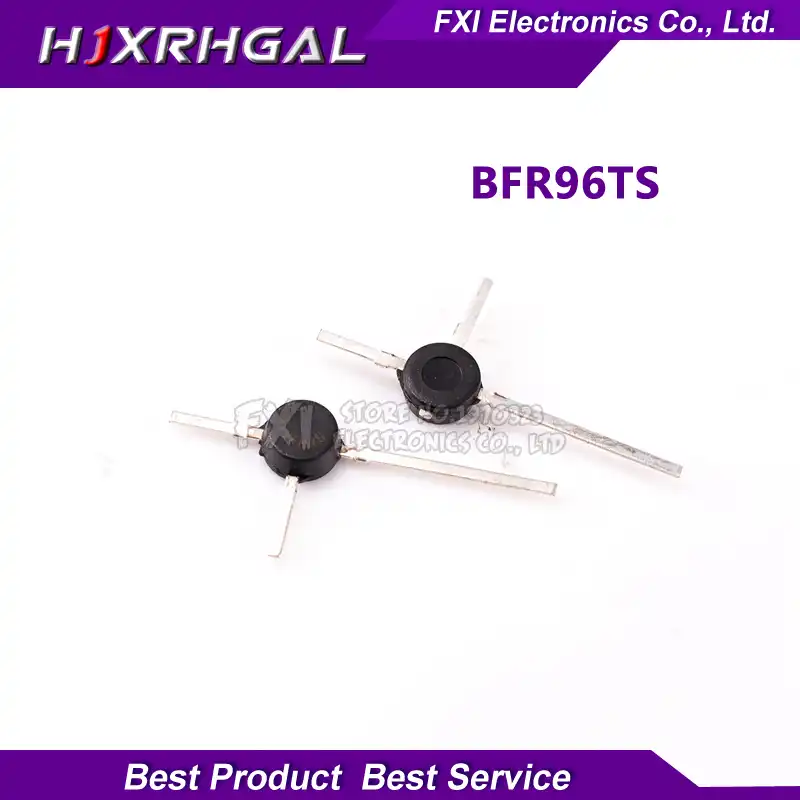
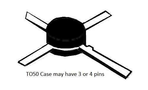
I bought some high freq transistors from China BFR91a and 96 to do some random radio stuff and I think they sent me something else in place of the 96 cuz it looks like they manually chopped off a 4th lead.. why would i see a tiny piece of a lead on all of them like that? The 91a’s look normal and have it printed on the case


 primal warren
I suspect the leadframe is made with 4 leads and cut afterward as part of the finishing process.
restive fjord
I saw a drawing that indicated that the fourth lead, when not cropped, is a second Emitter lead. I assumed that meant there was zero ohms difference between the two Emitter leads, and no difference at the silicon level (single Emitter package).
The Collector is the long lead, when the gap is to the left (top view).
restive fjord
Oh good! How did I not see that before
They are so tiny but these are used often for RF power amplification for 100-300mw output
restive fjord
It doesn’t look big enough to dissipate enough heat for that
primal warren
I think a fair amount of heat is conducted out the leads.
restive fjord
@primal warren may I pm you about the parts exchange?
primal warren
Yeah, go ahead
restive fjord
Ok.
restive fjord
I’m trying to amplify the rpitx output from the Raspberry Pi with that bfr96. I got the transistor biased so half the V is across the transistor / half across the collector resistor. Trying to think of a way to detect RF power output since I’m not sure its working (lack of equipment, got a rtl-sdr tho).
I’m thinking like output goes to a shottkey diode then a small capacitor then use an arduino’s analog adc to give a number (could amplify the dc on the capacitor with an opamp if needed). I’m not sure how I could make that be a 50 ohm load though.. I’m just getting back into electronics after years of nothing so I’m rusty 😎
Also have no clue what the Rpi should expect as far as impedance. It wasn’t designed to output RF, so I looked up max current and just got a resistor so I don’t blow it up. Like: Rpi pin 4 —> 270ohm —> 10000pf cap —> Base of BFR96.
restive fjord
@restive fjord what freq are you trying to obtain?
You can find an analog power meter pretty cheap if it isn't above hf
primal warren
For a 50Ω load, just use a couple of 100Ω resistors in parallel. Then put your peak detector in parallel with that. The Pi is a high impedance device, you might want a higher resistor than 270Ω.
You'll probably want a voltage divider between your peak detector and Pi ADC as well: you don't want to present more than 3.3V to the ADC.
restive fjord
I used a 270ohm because I looked up the max current for gpio and 270 was barely under the limit. I ended up making another stage with a bfr91a (I kept seeing that used to drive a 96 in schematics online) but these things for some reason are hard to bias. They love to go full on or full off so I’m still messing with it.
What do you mean by peak detector? The amplifier with the 96 does appear to be creating wideband noise on my sdr display. I’m going to have to get a good oscilloscope so I’m not so blind to what’s going on. I’m trying to figure out more about how the bias works - the ratio is important (divider from - and + going to base) but I don’t know what the size does... like 9k to + and 1k to gnd vs 90k to + 10k gnd. Both might put the transistor in the center where CE voltage is half the supply but wondering what it does to current and voltage gain.
restive fjord
Well, if you want power out, you have to put power in.
You can't put 1/12,384 of the desired output power, into it, and expect that level of output.
What I do is start with high values of resistance, and take measurements.
I = E / R
Then lower them 15 percent. Take measurements again.
primal warren
As for "peak detector", that's just a common name for the circuit configuration you mentioned with a Schottky diode and capacitor.
restive fjord
Then (of course) the next step is to bat it around on the 2 meter rig with the other hams and see what they have to say about it. ;)
restive fjord
I'm liking that Citizens Broadband Radio Service (CBRS) :
FCC Part 96:
Rules governing the Citizens Broadband Radio Service are found in Part 96 of the Commission’s rules.
restive fjord
Well I think I figured out one of the transistors is bad. No voltage drop from base to emitter, basically it acts as if the leads are not connected to anything. So I’ll test them before using.. bought 10 of each they were only like a dollar from China
I built a similar amp for the Pi using a random transistor I had and it did amplify so maybe these ones are from some kind of failed bin. $1 including shipping
 autumn tinsel
I want to connect a radio transmitter directly to a SDR instead of using a pair of antenna. How do I find out how much attenuation to add? The radio says it has 10dBm output power
primal warren
10dBm is about 707000µV. Do you know what the receiver's input can tolerate without distortion/intermodulation/damage?
autumn tinsel
nope. it's a tv tuner
primal warren
Hmm, a TV tuner should be able to accept up to around 40dBmV input. 10dBm into 75Ω is about 59dBmV, so you could probably get by with 20dB of attenuation.
restive fjord
I brought up the Hammarlund HQ-140-X this afternoon.
https://www.universal-radio.com/used/u938lrg.jpg


Got it up to 100 VAC input to the power supply circuit.
Start hearing a distant station's audio, from the speaker, at around 79 VAC or so. 74 VAC isn't quite enough, to hear anything but some hiss.
I think there's some hiss heard from the speaker, at as low as about 63 VAC input.
I use a Viz Isotap II WP-27A isolation transformer with 5 volt steps.
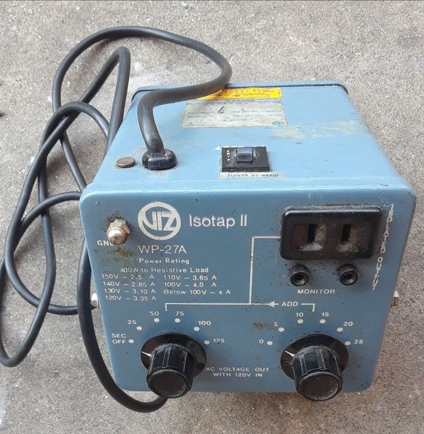


I don't have a true rheostat (I've forgotten what they're usually called) and changing steps on the Isotap is jarring, electrically.
I'd rather have the continuous type, though I suppose it may be possible to burn one out if there is a fault in the device under test. ;)
primal warren
I used to have a genuine Gen-Rad Variac, but I lent it to someone and never got it back. I eventually replaced it with an inexpensive no-name variable autotransformer.
restive fjord
Yeah I think Variac was what I was looking for. ;) Thanks.
https://en.wikipedia.org/wiki/Autotransformer
I haven't had one pop yet (a capacitor) so I don't know what slamming 5 volt steps at it does to the filter cap(s).
I bought three different lunch box CB's several years ago; all three popped. :)
(I did get a fourth and a fifth one that didn't pop and were put on the air for testing)
They're all about the same as the Robyn T-240D:
https://www.youtube.com/watch?v=50j217RguDo
restive fjord
I got my BFR91a RF amp working with rpitx-going to hook up another BFR96 stage. What I realized was I had the RF from the gpio pin going thru a resistor which is just way too large. Ended up just hooking it up with no resistor but thru a 10000pf cap. Max voltage swing should be +-1.65v I just sort of hope that it wouldn’t draw too much current from gpio running at rf frequencies but it hasn’t blown up yet.
primal warren
Depends on the frequency. I'd probably still have a series resistor to avoid overloading the GPIO pin (either from transistor load or reflected RF).
restive fjord
⚡
 cloud yoke
hey guys

"You see, wire telegraph is a kind of a very, very long cat. You pull his tail in New York and his head is meowing in Los Angeles. Do you understand this? And radio operates ...
how far do you think that will go
for range
within a house (not line of sight but not thick concrete walls)
primal warren
Easily within a house, even with a trivial wire antenna (don't know about the teeny spring antenna)
cloud yoke
yeah wire works fine
what about across a college campus
(a small one)
like 2 city blocks but without the city
primal warren
Should be doable ("LoRa" is short for "long range"). I've easily gotten over a kilometer with the 433MHz version. The 900MHz one won't get quite as good range, but should still be a solid performer.
cloud yoke
oof yeah
USA be like no 433
wait can I use 433 if I have my tech?
cuz it's between me and myself
(sensor to a station)
primal warren
I'm not completely sure on that. I thought 433 was an ISM band in the US (with an overlap in the amateur band). If you were using it under the amateur Part 97 rules, you'd have to follow the station ID requirements, but ISM usage would be exempt from that.
cloud yoke
I thought 433 was ISM in europe but not USA
LPD433 (low power device 433 MHz) is a UHF band in which license free communication devices are allowed to operate in some regions. The frequencies correspond with the ITU region 1 ISM band of 433.050 MHz to 434.790 MHz, and operation is limited to CEPT countries. The frequen...
yeah looks like it's just europe
I guess the 900 won't take too hard of a performance hit tho
primal warren
Apparently the governing regulation in the United States is CFR Title 47 § 15.231 https://www.ecfr.gov/cgi-bin/text-idx?SID=57e3d98742373709e9f8f17ed3759834&node=47:1.0.1.1.16.3.236.21&rgn=div8
Apparently brief (up to 5 second) transmissions are allowed, scheduled transmissions are not, but polling is permitted.
Polling should not exceed 2 seconds of transmitting per hour, unless "the duration of each transmission shall not be greater than one second and the silent period between transmissions shall be at least 30 times the duration of the transmission but in no case less than 10 seconds."
cloud yoke
so like if there's an if(stuff happens) then send signal
that's not scheduled
what does polling mean tho
primal warren
It seems to me that would be allowed. Since LoRa uses brief packets, it should be simple enough to stay within the regulations.
restive fjord
band plan
http://www.arrl.org/band-plan
 floral salmon
Can you use Lora to transmit audio
 dusk sequoia
Is there a trick to getting the Adafruit Lora rfm9x module to be recognizable on the board using Circuit python.
normal drift
@dusk sequoia there is a guide here https://learn.adafruit.com/adafruit-rfm69hcw-and-rfm96-rfm95-rfm98-lora-packet-padio-breakouts/circuitpython-for-rfm9x-lora

Adafruit Learning System
Radio transceiver modules for long distance data communication
Which MCU board and RFM9x module are you using?
dusk sequoia
I’m using a feather m0 rfm9x board and it’s not recognizing the Lora module
normal drift
@dusk sequoia Can you post the code you are using? -- as well as any error messages. Which circuitpython .uf2 file did you load to your board?
dusk sequoia
4.1.0 circuit python
Error “can not detect LoRa Module.Please check wiring!”
Board.RFM9X_CS
Board.RFM9X_D0
Board.RFM9X_RST
I have changed the USB cord as well toone that was working on my other broads
normal drift
@dusk sequoia Can you post the code you are running. I don't have a feather_m0_rfm9x but I do have an RFM9x featherwing attached to an M0_adalogger and it is working with the rfm9x library.
I ran the rfm9x_simpletest -- posted here -- you should just have to change board.D10 tp board.RFM9X_CS and board.D11 to board.RFM9X_RST. board.RFM9X_D0 is not used in this test
 carmine matrix
Hi there! I'm interested in tinkering with some of the RF controlled devices in my house, such as ceiling fans, but I'm still pretty new to radio tinkering. Can anyone offer tips on how one would go about transmitting an OOK signal on 303.914 MHz?
I'm wondering if there's a common way people build a circuit that can do that, perhaps certain ICs that aide in accomplishing that
primal warren
Probably a Pierce oscillator and a SAW or crystal for that frequency is the easiest approach
carmine matrix
Hmm, okay thanks. I'll look down that path.
How precise does a transmitter/receiver need to usually be for that kind of device?
I've got a lot to learn about RF 😅 trying to make this a good beginner project
primal warren
Depends on the receiver, I suppose. The description of this one says it's somewhat "indiscriminate", and looking at the pictures, it does look like an LC circuit with fairly low Q (and therefore selectivity): https://www.sparkfun.com/products/10533

These wireless receivers work with our 315MHz transmitters. They can easily fit into a breadboard and work well with microcontrollers to create a very simp
The 315MHz transmitter looks pretty simple, just a SAW filter and a little circuitry https://cdn.sparkfun.com/datasheets/Wireless/General/TWS-BS-6_315MHz_ASK_RF_Transmitter_Module_Data_Sheet.pdf
carmine matrix
I was wondering if a 315mhz transmitter would be usable for this
The operating frequency in the sheet says +/-250khz, which would be higher than the frequency I'm looking at.
I'll probably take my remote apart soon to see what it's built from,
primal warren
303.914MHz is a bit of an oddball frequency. Looking at SAW resonators on Digikey, I see 303.825 and 304MHz. At least you can get a through-hole version of the 303.825MHz one (Murata RF3210).
Some schematics and useful info here: http://www.jap.hu/electronic/rf/trdesap.pdf
You can, of course, build an LC transmitter (Colpitts or Hartley) at any frequency you like, but you'd probably need a frequency counter or similar to tune it properly.
restive fjord
You can use a Raspberry Pi as an SDR with free software called rpitx on GitHub. Will let you transmit up to 1500mhz and you can drive it with I/Q signals. I believe there’s also a program to record any signal bandwidth from a SDR receiver and play it back with rpitx (comes with it)
I still am amazed by rpitx.. how did the creator figure out how to drive a gpio pin with I and Q signals accurately... amazing
restive fjord
Hello, ive been trying to figure out how to connect hm10 bluetooth module to the arduino mega. I've been following a tutorial. https://www.mrswirlyeyes.com/tutorials/bluetooth_hm_10. So far I have the hardware connected with the module blinking, but when I type in AT into the serial console, nothing appears even when I have NL and CR. When i disconnected the TX and RX, I see my input. I followed their code, except I changed the TX and RX to 1 and 0 respecively
primal warren
Hmm, with a Mega you can use one of the hardware serial ports and have a simpler solution. Also, using 1 and 0 isn't going to work because those are already used for host communication, so you can't use them for something else at the same time.
restive fjord
alright, i will switch it from 1 and 0. I also read that i have to build a voltage divider for the hm10 rx since the mega outputs a 5v logic and the hm10 only takes 3.3v logic
primal warren
Right. I'd suggest using one of the Mega's hardware serial ports (since they're available) instead of SoftSerial.
restive fjord
alright sweet, its working on my microcontroller. Just gotta do the same thing except on a raspberry pi. Thanks for your help @primal warren
nimble depot
@restive fjord Many modern Pi models have BLE built in.
restive fjord
im using raspb pi 4 which has ble 5, will it connect to hm10 since it uses ble 4?
i assumed it wouldnt so thats why im putting an hm10 on the rasp pi
i want two hm10 to talk to each other for now. one on a rasp pi and another on an arduino
nimble depot
I'm pretty sure the Raspberry Pi 4 supports Bluetooth 4.x. Bluetooth 5.0 is just getting started, and supported by very few devices.
Adafruit's Tony DiCola discusses using BLE on Pi:
https://www.youtube.com/watch?v=5fQR2PHMDWE
Enjoy the videos and music you love, upload original content, and share it all with friends, family, and the world on YouTube.
restive fjord
i see thank you for this information. Im reading more about it. You think it would be better to just use the built in BLE rather than have my own
as in the HM10
nimble depot
@restive fjord On the Pi, that's what I'd try first.
nimble depot
Interesting, unanswered question on the Forums about LoRa range peculiarities. “Reliable” options reduce range down to a few meters?! Can someone familiar jump in and looks at this >30 day unanswered question?
restive fjord
People are saying about a kilometer, iirc.
I have no idea how that maps to reliable though. My experience is 144 MHz packet radio (ax.25) where retries (and collisions in timing) are accounted for.
primal warren
They don't say what kind of antenna (if any) they're using. I might play with it when I get some free time, but it seems to me like it ought to work.
restive fjord
I’m really curious about trying to make a custom gnu radio project with sdr and custom spread spectrum- if spreading it lets you increase the power legally (I’ve seen 1 watt LoRa devices being sold) I’m curious to try it.
tiny dust
@primal warren are you good at HFSS?
@restive fjord you should look up regulations. IIRC SS emissions are regulated pretty heavily, at least in ham radio
and no you won't get magically more power by spreading the signal. most regulations specify X watts at the feedline, doesn't matter what the waveform looks like
when i think i have hfss figured out
primal warren
Which HFSS?
normal drift
@vocal veldt I'm am making good progress on enabling interrupts for the RFM9x/69 -- So far it involves minimal changes to the library so I think it can be incorporated with no breaking impact. I hope to have PRs ready later this week.
vocal veldt
@normal drift Super neat, esp. bc its not breaking
Are you going to add examples? This work is perfect for the Radio Bonnet imo.
normal drift
Yes -- I am testing now with a bonnet (rfm69) and will add examples with the PR. Right now it only uses the interrupt for RX. and I need to filter out TX interrupts or handle them -- not sure it is worth it for TX. But all the code is in the example, not in the library.
TX also raises the interrupt signal -- just need to ignore it in the handler.
oooh -- I just remembered where I put my RFM9x bonnet!!
vocal veldt
LOL - I have mine in a box called "LoRa" that's literally overflowing, need to sort it out better...
restive fjord
So I got analog devices to send me more free samples. Got two types of mmic RF amps— 1/2w and 1w broadband amps. Tiny.. anyway managed to hook one up and use rpitx as a driver. Works amazing into two 100 ohm resistors in parallel and they get a little hot. So it accepts square wave input and amplifies harmonics but only up to 3-5th.
Cool little devices they got RF in RF out and gnd... and ya put a few caps on and a choke and it works
restive fjord
@restive fjord nice!
primal warren
Those MMIC amps are pretty handy
restive fjord
Yeah I barely was able to solder the tiny so-39 part but I had an adapter for something else that was good enough. Surprised how perfect it works
primal warren
Nice
 fallen matrix
Hey there @primal warren and friends, Do you have any experience with noise filtering? I've got a video transmitter I'm looking to filter out noise for, and trying to keep it as DIY as possible. I have a great selection of ceramic and electrolytic caps, I'm just stuck on making a homemade inductor. The way I understand it, the goal is to wrap a conductor around a ferrous core which will aid the cap in filtering out any drops in current under load. My question: Is it important that this ferrite core is shaped like a ring? What's to stop a conductor wrapped around let's say a 1" long steel bolt from working the same way? I know the shape of the magnetic field would be different... Any thoughts?
primal warren
A steel bolt will work as a core, but for higher frequency filtering, it's good to have multiple small magnetic domains instead of one large one.
This is why ferrite, powdered iron, and bundles of rods or laminations are popular
The ring shaped ("toroidal ") cores have the advantage that they contain their fields so are self shielding
fallen matrix
I see. So if I have some ABS filament that contains iron, marketed as ferromagnetic, you think that would work better?
primal warren
It's probably not very concentrated iron so I'd guess it would have less effect overall but might have a more balanced response
fallen matrix
I think I might take a piece of iron stock to a grinder, get a few grams of dust together and mold one with some epoxy. I know these cores are sold for pennies, just can't wait on the shipping as the project needs to be completed by tomorrow, haha. I really appreciate your insight into this. It's somewhat of a black magic to me.
primal warren
A bundle of iron picture hanging wire can work too
And you may as well try the steel bolt
fallen matrix
That makes sense, I'll try the simpler solution first.
fallen matrix
While digging through a couple of trays, I stumbled upon an old ESC with a ferrite ring and decided to use that. Didn't think about it when putting it together, but is there any consequence of routing the ground and video signal wire through the center of the core? Also used .5mm magnet wire for the turns around the core.
normal drift
For the RFM69 or RFM9x modules, is there a need to set a PULLUP or PULLDOWN resistor on the Interrupt (DI0) line. The signal is active high.
 graceful spindle
It looks like Adafruit did a modification to the RadioHead library... it appears to be able to support M0 based boards .... I am wanting to use the RH_ASK example ... I have the inexpensive 433mhz FS1000A boards ... will this work on a Feather M0 and if so / what pins ? (Transmitter ? / Receiver? ). It looks like Adafruit did a modification to the RadioHead library... it appears to be able to support M0 based boards .... I am wanting to use the RH_ASK example ... I have the inexpensive 433mhz FS1000A boards ... will this work on a Feather M0 and if so / what pins ? for Transmitter ? / for Receiver?
primal warren
Should work with an M0
 regal dust
for a 915MHzz LoRa shield, can anyone spot why the following would cause an Arduino UNO to hang?
// Singleton instance of the radio driver
RH_RF95 driver(RFM95_CS, RFM95_INT);

// Class to manage message delivery and receipt, using the driver declared above
RHReliableDatagram manager(driver, SERVER_ADDRESS);

void setup() {

  //initialize LoRa
  pinMode(RFM95_RST, OUTPUT);
  digitalWrite(RFM95_RST, LOW);
  delay(10);
  digitalWrite(RFM95_RST, HIGH);
  delay(10);

  // initialize reliable datagram manager
  if (!manager.init()) {
    Serial.println("*** RH reliable datagram manager init failed. Stopped.");
    while (1);
  }

  // make sure board frequency is set correctly
  if (!driver.setFrequency(915.0)) {
     Serial.println(F("setFrequency failed; stopped."));
     while(1);
  }
  Serial.println(F("RF95 frequency set to 915.0 MHz."));
...```Nothing obvious, do any of the prints happen?
regal dust
I see the "RF95 frequency set to 915.0" bit in the serial console, but nothing after that.
primal warren
I don't see any of the code after that but that's where I'm look
regal dust
i put a test Serial.println("got here OK") inside loop() and it gets there.
but that setFrequency() command causes the very first line inside loop(), if (manager.available()) { ..., to fail (that is, it falls through to the else { ... block). if i comment out the setFrequency bit, the loop works normally.
i'm wondering if there is some interrupt conflict going on. this is with the Reliable Datagram example sketches.
primal warren
Hmm don't know but I agree with your logic
Maybe there isn't anything available to start with but presumably it comes back around to check for fresh data
primal warren
I'm fond of LoRa. Was easily able to get around 1km range with simple wire antennæ with the 433MHz ones.
 rich ferry
LoRaWAN with TheThingsNetwork is pretty neat too. The gateways forward your traffic to TTN then TTN forwards it to you over normal(ish) internet stuff, encrypted over the air and from the gateway.
Unfortunately the only gateway in town is behind a hill from my house right now. They're going to move it to a taller building, and not behind a 2' thick concrete parapet, at some point
 hot vessel
Does TheThingsNetwork charge for using the network?
normal drift
No - not for the "community edition"
hot vessel
nice!
restive fjord
@primal warren is there any international seller for LoRa 433 - 933 mhz modules
primal warren
Probably? Most of them seem to be based on the HopeRF RFM95 module.
restive fjord
can someone please give me a noob-friendly explaination what RF_N,RF_P and RXTX do? (https://www.ti.com/lit/ds/symlink/cc2590.pdf)
primal warren
RF_N and RF_P are the negative and positive radio frequency outputs, relative to the RXTX center tap (which is used to provide a voltage to switch the downstream CC24xx/CC25xx devices between receive and transmit). The RXTX pin isn't required if RX/TX switching by voltage bias isn't needed.
restive fjord
Thank you ^^
 strong blaze
Hello, I am working with an RFM69 with the OLED (pid=4073) and I am trying to pair it with another radio (not an RFM69), is that possible?
I have both radios at 433MHz and both have FSK modulation
Any help or tips are welcomed
normal drift
@strong blaze From your forum post, I recall you are using CircuitPython to operate the RFM69. Are you also planning to use CircuitPython to operate the other module or does it use some other software? If so, can you provide a link to documentation on the other module hardware and software?
 amber flare
Does anyone know what are the differences between the LoRa Featherwing (https://www.adafruit.com/product/3231) and the LoRa transceiver breakout (https://www.adafruit.com/product/3072)?
"You see, wire telegraph is a kind of a very, very long cat. You pull his tail in New York and his head is meowing in Los Angeles. Do you understand this? And radio operates ...
I'm thinking of getting a feather with Lora RFM95W (https://www.adafruit.com/product/3078, not sure what the W stands for) and just experimenting with another rfm95 transceiver (with some other microcontroller)
I was wondering if the mentioned transceivers are identical
normal drift
@amber flare they function the same -- the featherwing is just configured to plug into a feather-type MCU board. I think they are the same module -- just attached to different boards.
the guides do point to different data sheets v1.0 vs v2.0 but I m not sure if that maens thay use different versions or the gudes are not updated....
I use both interchangeably
amber flare
@normal drift Thanks! I don't own a feather (yet) because I don't write in python.
This might be the push to jump into the newer chips like that M4
normal drift
Note, I have not used the 32U4 version -- I have used the M0 version -- I prefer the breakout and featherwing then attach to the MCU of my choice. usually an M4 since I do mostly work with Circuitpython
the All in one M0 rfm95 is difficult to use with Circuitpython because of the memory limitations
normal drift
No -- you can use Arduino with it
You can also use the RFM95 breakout with a Raspberry pi
amber flare
I work with the platformio framework now, which doesn't support python so I need to deliberate hard on this
I think it would be probably better to get 2 transceiver breakouts
normal drift
You should be able to use platformio with any of the MCUs and the RFM95
normal drift
platformio allws you to import arduino libraries, correct... so it should be fine.
amber flare
yeah... I haven't actually tried compiling micropython
You have good words about the M4?
normal drift
well, you can just download circuitpyton -- no need to compile it
I like the M4's a lot -- also the nrf52840's
amber flare
I'll probably get an M4 feather and the featherwing and a transceiver then
that should start me off nicely
normal drift
that will give you a lot of options!
amber flare
I got my nrf52840 for christmas last year
never had the chance to tinker with it yet either!
its been a year full of hardware releases
normal drift
I know the problem of having too many toys and not enough time 😉
amber flare
thanks for the advice
glad I didn't get the m0 feather, it was tough reading the fine print
I couldn't get any benchmark tests between the M4 and an atmega2560
I guess I got to try it out myself
normal drift
It's fine with Arduino -- and I use one of the M0 featherwings for a simple project, but it is very easy to run out of RAM with circuitpython
primal warren
With direct (Arduino) style use of the chip, that's a ton of RAM. CircuitPython, on the other hand, while super convenient and powerful, can gobble up RAM in a hurry.
normal drift
M0 only has 32K RAm
primal warren
Even that is huge by Arduino standards (I think 16 times the ATmega328 RAM)
normal drift
Yes -- for Arduino the M0 rFm9x feather isa great device
amber flare
Can the M0 be used with Arduino to save on memory then?
The lora featherwing is out of stock 😦
normal drift
arduino supports M0 and M4 and all the MCUs I have worked with.
And the Radiohead library for Arduino has a lot more implemented than the CIrcuitPython library at this time -- It is a Work in Progress to add more features to the CircuitPython libraries.
SO -- don't take my comments as discouraging you from using the M0 Lora feather .. I just don't recommend it for CIrcuitpython
restive fjord
That's good to know. ;)
Still thinking about making the investment in LoRa hardware.
It's obviously what I want to try first, over the other one. (RFM69foo?)
amber flare
Better to find out now then later! I wanted to buy the feathers to try out circuitpython anyways
I didn't know it required so much memory overhead
I'm getting two transceivers and an M4
and praying that the featherwing comes back soon
normal drift
Good luck with them.. Have fun!
@restive fjord - the LoRa boards are great and I am using them with M0,M4,nrf52840, STM32F405 and various Raspberry Pis....
mostly with CircuitPython, but I use Arduino and other libraries to check the functionality of my work on the CP library
restive fjord
Jerry, do you have a favorite bolt-on module to retrofit existing SAMD51 targets?
normal drift
the LoRa feather wing is nice but out of stock -- I just use the breakouts on a breadboard.
restive fjord
Yeah that sounds good. ;) I'm not married to the feather form-factor; I have representations in all of the offered form factors now. ;) /haha
normal drift
for Raspberry pis -- I like the "bonnet" with built in OLED
restive fjord
I found that by using the Extra Long Header pins, one row short (narrow at the breadboard) I can 'staple' any breakout to a perfboard with acceptable contact friction (up top).
Going to try the stacking headers using the technique, soon.
The last one I did (STM32F405) was so reliable I haven't had to fool with it after construction. I used a PermaProto (which looks really nice compared to the phenolic resin type perfboard).
normal drift
not sure I am following -- do you have a picture?
restive fjord
I'll try to take one. ;) The angles are hard to do.
normal drift
is this a friction fit -- not soldered
restive fjord
Total press-fit yes
That's the entire point. Plus it's 100 percent reusable this way.
stapled solderless technique extra long header pins folded over (to bind) using wire wrap tool to bend each pin.
The orange horizontal bungee straps across this printer stand to offer an anchor point for the lightweight modules there. ;)
The earlier technique (Trinket M0, upper left) wasn't as effective.
The STM32F405 pins aren't folded over (at all) up top. Just underneath.
normal drift
ok -- I see - so the STM is not even soldered to the header?
restive fjord
The side profile is in the shape of a boat hull (wide up top; narrow down low) for the header pins intercept angle to the target.
No solder anywhere in that photo, except factory fabrication stuff. ;)
normal drift
ok - I get it -- the angle helps keep pressure on the contacts
restive fjord
Basically you press down really hard on the target's MCU with your thumb.
Then secure underneath.
(by folding over)
No folding over (at all) up top.
It's wedged tightly.
That works because the number of rows of spacing was reduced by one row, from parallel.
I was really surprised how much better that worked than the parallel technique used on Trinket M0 (upper left in the photo).
I used stacking header pins (ganged) to extend the pins on Trinket M0, which offers better continuity (fewer intermittents).
normal drift
interesting way of doing it.. I just solder on stacking headers to everything!
restive fjord
You can see the stacking header attached to Trinket M0 in the photo.
restive fjord
It's a little pricey of an approach but is entirely solderless and works reliably for my use cases (mostly USART interconnects at 115200 bps).
@normal drift You're very welcome! I really like this technique.
(I used binder clips and shoelaces to secure the long breadboard to the bungee in the photo haha)
I also used waxed string to bind the USB-C cable to the other one, to give both mechanical stiffness.
normal drift
I would expect no less from a a ham 😉
restive fjord
haha. Yeah it's a very old habit, to make multiple cables into harnesses. (there's that word! harness)
This was just a one-off and is my ugliest implementation to date.
A week earlier it was several Pomona MiniGrabber to banana cables doing the same things the breadboard and Dupont jumpers now do.
normal drift
I have to run -- the dog is pacing at the door and I ignore her at my peril! Be back later.
restive fjord
I still don't have a B0 to Vcc +3.3 SPST for booting this. ;)
(can be momentary, I think)
(just chord with reset, leading with B0 in a 'staggered timing' chord) (chord as in playing the piano)
primal warren
I think a staggered timing chord is an arpeggio?
restive fjord

For all you viewers misled by that guy who thought it was cute to upload an incomplete version, here's the whole episode - including the disturbing piano segment you've all been waiting for!
Enjoy!
They were far ahead of their time!
(Art Clokey)
 latent jungle
Hi there! I plan to build an 80m foxhunt (amateur radio direction finding) transmitter out of a CircuitPythonExpress. As the processor runs on 40MHz or something like that, it should be fast enough to generate the necessary frequency in the 80m band (roughly 3.5 MHz), at least I hope so. The other option is to use a Si5351A (waaay overkill, I know, but I have one laying around), but frankly I would prefer the bare CPX.
Has anyone experience in using the CPX board for something alike?
restive fjord
@latent jungle I have no idea how that works in practice.
That said, only a few pins on each MCU can output the clock onto a pin.
Not every Adfruit SAMD21 target maps such a pin to a (user) solder pad.
(Feather M0 Express or Feather M4 Express does map that pin; I don't remember which one of the two; similarly for Metro M0 or Metro M4 Express).
(It's a very weak signal, also - not sure it is suitable as a source for external uses) (I think it's meant for research and development only, meant for, say, looking at it on an oscilloscope for a basic sanity check when noodling with clock settings).
If you're just trying to use some other output method, then you may be dealing with 'shaping' the output to something useful in radio work.
There's a whole thing about wave generator foo I haven't looked into; was under the impression that was oriented towards something less than 500 KHz.
On the other hand if this is a toy for a foxhunt, it can probably be pretty awful so long as it's a Part 15 device (in spirit haha).
If it's meant to be a Part 97 device, I think you need a fairly clean (narrowbanded) signal.
Especially on 80m since there's lots of listeners there.
There are probably inexpensive modules you can acquire that are easier to work with (and may in fact benefit from the presence of a microcontroller for generation purposes).
latent jungle
@restive fjord Thanks for your response! Well, probably you are right, easier to build a separate narrowband oscillator and just "modulating", say switching it with a controller.
Not sure what Part 15 or 97 exaxtly specify, I am not relly familiar with the exact FCC regulation, as I am from Germany, so ham radio is governed by a different set of rules, but we also have some regulations concerning bandwidth, and it also was a concern which bothered me. As it should be just a local fox beacon I would be fine with really small power, even in the milliwatt range (target was 1W max, with more probably something between 10 and 100 mW). But as said, building a small oscillator would be probably easier and more "ham-like" than using a square wave and filtering the heck out of it... 😉
restive fjord
FCC Part 97 covers Amateur Radio.
Part 15 is what's cited on the back of most of your home gear that radiates RF at a low level.
(wireless router for example)
Sorry I was reading USA-centrically. It's hard to remember this place is inherently international, sometimes. ;)
Part 15 basically says 'this device radiates RF. It must a) not interfere with other devices too much and b) tolerate interference from other devices like it'.
Its their way of saying 'expect it to work very locally, and not at all, at any distance, or in 'crowded band' conditions.
That's Part 15, and I think commecial devices need Part 15 certification (not sure on that).
In the US, generally speaking, hams can devise their own gear, under Part 97, and they don't need to have it certified.
(They're expected to be judged by their peers for compliance with the regulations on transmission, under Part 97).
Generally, that means a clean signal at reasonable power.
(and at least somewhat typical of the emission 'type')
The American Radio Relay League (ARRL) is the national association for amateur radio, connecting hams around the U.S. with news, information and resources.
http://www.arrl.org/part-97-text
§97.307 Emission standards.
That's the basis for what hams are to do wrt Part 97 compliance.
📻
normal drift
@vocal veldt I am having real issues with the Raspberry Pi missing Acks that comeback too fast. In the CP code I added a configurable delay to fix that , but compatibility with Radiohead remains to be a problem. I am tempted to enable interrupts by default for the RPi and see if I can elimate that problem. I wan this to be fully compatible with the Radiohead library used on Arduino
vocal veldt
@normal drift Do you think the collision is occurring from the RX or TX side?
normal drift
I think it is mostly RX -- can't get the packet procesed in time before the next packet especially an ACK comes in.
vocal veldt
@normal drift I have 0 issue with you enabling interrupts on the Pi.
If we had interrupts on CircuitPython, i'd have that by default too
this type of thing should be async
normal drift
yes -- I'll do that next and see how it goes. Interrupts added some new issues, but I think I see why. Should not be too hard.
vocal veldt
@normal drift it'd be interesting to rewrite an example similar to how Paho-MQTT/MiniMQTT work
i.e: listen_in_background and process foreground tasks
normal drift
I also found this https://pypi.org/project/raspi-lora/ very similar to what I have been doing...
vocal veldt
for pi, the bonnet is the demonstration for this since it has buttons and should be listening
oomg a lora lib I havent read yet
normal drift
I'm not completely convinced it is fully "reliable" but it does work and I have been checking compatibility with it as well.
vocal veldt
RFM9x doesnt support encryption, this does
I feel that's because we didnt have a library at the time for CircuitPython, though.
vocal veldt
We could do a conditional import for PyCrypto on RasPi clients, if not we import Adafruit CircuitPython RSA ...though they use AES
normal drift
Once we get it all working -- the "conditional" coding will be another discussion...
vocal veldt
ya - Radiohead uses https://rweather.github.io/arduinolibs/crypto.html
I'd love to test it once you PR in , I got a bonnet set up here
normal drift
great -- I'll get going on it.
vocal veldt
https://github.com/adafruit/Adafruit_CircuitPython_TinyLoRa/blob/master/adafruit_tinylora/adafruit_tinylora_encryption.py @normal drift I was pretty sure I wrote AES before for CircuitPython
GitHub
Adafruit Tiny LoRa. Contribute to adafruit/Adafruit_CircuitPython_TinyLoRa development by creating an account on GitHub.
We should break this out from Encryption to Adafruit_CircuitPython_AES. There's also some profiling I feel we need to do, to speed up the loops in this (that's the bottleneck)
 lunar willow
Alright, I need some help. So I'm trying to built a portable FM transmitter, except there's a catch: I need it to transmit at 72.1Mhz
I tried using a Si4713 board but that'll only go as low as 76Mhz
primal warren
Hmm, there are a few possible approaches. One is to choose a different chip that supports the range you want. Another is to build a simple FM transmitter out of discrete components. Yet another is to use the Si4713 but with a different crystal/clock frequency. Which appeals to you depends on what skills and materials you have available and what sort of transmitter you want (voice, digital, beacon, analog, etc.)
lunar willow
Actually I just figured out my Pi Zero can do it off of one pin. All the chips I found only go down to 76MHz and I don't have the components to do a discrete circuit. It's transmitting a repeating audio track using an "antenna" of conductive thread woven into a vest
 granite spear
The idea about giving the Si4713 a different reference clock would probably work, since it's just a 5% difference to fool it into thinking that 72 is 76. It even has registers where you tell it what the clock is, so it'd be a pure software hack.
vocal veldt
ohohoooo @normal drift

Hackster.io
With an Arm Cortex-M4 at up to 48MHz, 256kB of flash, 64kB of RAM, and a radio capable of LoRa, (G)FSK, (G)MSK, and BPSK modulation.
restive fjord
@lunar willow You’re probably talking about Rpitx I can confirm it works GREAT for transmitting anything
primal warren
Back in the days when you payed per drill hit, yeah. These days, go nuts. Via stitching is totally a thing.
I suppose you could get to the point where the board is so perforated it becomes a set of snap-off sub-boards.
lunar willow
@restive fjord Yeah I was honestly shocked by how well it works without any dedicated hardware. With my vest antenna it has a range of at least 30-50ft
primal warren
Nifty!
primal warren
Pretty!
 stone dust
Anyone know the big differences between the bluefruit le sniffer and bluefruit le friend?
primal warren
It's right in the Sniffer product description: "This Bluefruit LE Friend is programmed with a special firmware image that turns it into an easy to use Bluetooth Low Energy sniffer."
restive fjord
@lunar willow I was able to build a tiny MMIC circuit and amplify the Pi output to 1/2watt.. had it going into a dummy load because it amplifies all the harmonics but it’s an easy way to amplify radio stuff
primal warren
MMICs are really handy for tricks like that.
vocal veldt
@normal drift so you'll need a SX127x chip but this is awesome https://github.com/manuelbl/sx127x-probe

GitHub
LMIC LoRa Timing Analysis. Contribute to manuelbl/sx127x-probe development by creating an account on GitHub.
https://github.com/manuelbl/sx127x-probe#analysis < specifically
GitHub
LMIC LoRa Timing Analysis. Contribute to manuelbl/sx127x-probe development by creating an account on GitHub.
We could do something similar with a SX1276, but the timing analysis of this probe is super tight
inexpensive LoRa+PSOC https://heltec.org/project/htcc-am01/
 normal drift
@vocal veldt Thanks! So many things to try..... I should start by hooking up my logic analyzer just to see what the SPI traffic looks like...
vocal veldt
Totally, someone at the prv. TTNNYC meeting showed off their results with that SPI sniffer
super interesting results, too. especially since when doing field applications, gateway placement is more important than node placement
normal drift
WooHoo! the RFM9x 915MHz bonnets for RPi are back in stock...
restive fjord
📻 🕳️ 🐇
normal drift
it's a bonnet 🎩 not a bunny 😉
restive fjord
yeah but rpi bonnet .. just said rabbit to me ;)
bonnet rpit .. bonney rapit .. bonny rappit .. bunny rappit .. bunny rabbit ;)
normal drift
makes complete sense now....
restive fjord
that all happened in my head in under a millisecond. ;)
normal drift
😎
strong blaze
any resources avaiable on what makes 2 radios compatible with each other?
I am working with SX1231 and AX5043
But I am not sure if they can be configured to talk to each other
My first attempt was to set them at the same frequency and same modulation (FSK) and that didn't work
🤷♂️
primal warren
The Radiohead library does a decent job, if you configure the radios similarly, it translates that into radio-specific configurations fairly well
strong blaze
what would "configuring the radios similarly" consist of?
I am fairly new to anything radios-related
so both radios have to be configured to the radiohead library? or the packet structure of the library?
primal warren
I use the Radiohead library to operate the radios, it includes support for a whole variety of different radio chips. If you set them for the same frequency, mode, encryption, etc., they might talk to each other
vocal veldt
@normal drift yeah, they have a new module design
normal drift
@vocal veldt just got one of the new style -- works well so far.
vocal veldt
Yeah, I tested one after it came off the line, same SX1276
the new SX1262 is promising https://www.digikey.com/en/product-highlight/s/semtech/sx1261-and-sx1262-lora-transceivers
 tepid zodiac
Hello, does anyone here have experience with Adafruit's BLE Sniffer?
normal drift
This has been getting a lot of press in the past few days https://threatpost.com/lorawan-encryption-keys-easy-to-crack-jeopardizing-security-of-iot-networks/152276/ sigh... some people take all the fun out of things....
primal warren
Time for double encryption? Tor? sigh
rich ferry
that boils down to "if you publish your encryption keys to github, anybody can decrypt your traffic". That's not cracking
slender current
@vocal veldt any chance you could put uf2s on: https://learn.adafruit.com/adafruit-airlift-bitsy-add-on-esp32-wifi-co-processor/upgrade-external-esp32-airlift-firmware I'm not sure I have arduino installed

Adafruit Learning System
Add a Airlift Bitsy Add-On to give your projects an extra-small internet enabled lift!
vocal veldt
@slender current That page follows the generic esp32 co-processor layout, but it makes sense since the pinout is board-specific to the itsy.
I'll make one for you tomorrow
slender current
could include one for each right? thanks!
vocal veldt
@slender current tbf they should all point towards https://learn.adafruit.com/upgrading-esp32-firmware

Adafruit Learning System
Keep the firmware on your ESP32 WiFi Co-Processor up-to-date!
nvm, it seems it's a mirror.
slender current
yup, looks like it
vocal veldt
I could add UF2s for: AirLift FeatherWing + Feather M0/M4 Express/Itsy M0/ItsyM4, and Metro M0/M4
vocal veldt
Sure
You're attempting to upgrade nina-fw I presume? If you have any ideas on how to make this process faster/easier, I'm all ears.
slender current
I was
but I haven't tried whatever it flashed with
trying to make my ble to io over wifi bridge
vocal veldt
oh - ble<->mqtt wifi bridge is neat! I'll make a UF2 in the AM, have a TODO for it now. Itsy M4 first
slender current
I haven't decided mqtt or just http. still figuring it all out 🙂
thanks, will poke io tonight
vocal veldt
I ❤️ MiniMQTT+IO...but I'm biased. both are fine
slender current
k, will start there
restive fjord
rofl 'not sure I have Arduino installed' ;)
restive fjord
Some mnemonics for Morse Code I learned:
H hitting the hip
F for the FAIRest
L he LOST his LID
Q HERE COMES the BRIDE (queen)
W the WORLD WAR
B BE a good boy
K KAN dy KID (candy kid)
V di di di dah (Beethoven's Vth symphony)
Many of the other ones can be based on those.
Like U (di di dah) is the same as F, but one element shorter.
https://www.youtube.com/watch?v=lOqe0oouN2s CQ Serenade
primal warren
Reminds me of the mnemonics for poetic meter.
restive fjord
I hear them as sounds, now, but back in the day, the mnemonics helped.
(probably because some of them have no mnemonics I'd ever learned and was unable to come up with them on my own, so I learned them by their sounds)
 umbral oxide
The channel subtitle says "All things radio: WiFi, Bluetooth, HAM". Do LoRa and SDR fit here?
granite spear
Yep, definitely.
restive fjord
You see, the wire telegraph is a kind of very, very long cat. You pull his tail in New York and his head is meowing in Los Angeles. Do you understand this? And radio operates exactly the same way: you send signals here, they receive them there. The only difference is there is no cat.
http://www.columbia.edu/~ey2172/einstein.html
 heady ferry
I am looking at my shiny new Adafruit Bluefruit LE SPI Friend, and I noticed there is a spot on the bottom for an "optional 32Khz Crystal". What is it for?
primal warren
As far as I can tell, by default it's using an RC oscillator which isn't super precise (±250 ppm) but supports using a crystal for higher precision. https://www.nordicsemi.com/-/media/Software-and-other-downloads/Product-Briefs/nRF51822-product-brief.pdf
I suspect that the crystal wouldn't be used by the default firmware, but other firmware could configure it. https://cdn-learn.adafruit.com/downloads/pdf/introducing-the-adafruit-bluefruit-le-sniffer.pdf
restive fjord
I think the STM32F405 has a power-of-two xtal and maybe a 12 MHz one as well.
 quartz surge
Hey I think I might have run into a bug on: https://learn.adafruit.com/multi-device-lora-temperature-network/using-with-thethingsnetwork
the code says:
lora = TinyLoRa(spi, cs, irq, rst, ttn_config, channel = 6)```
And on TTN's website under https://www.thethingsnetwork.org/docs/lorawan/frequency-plans.html it says:
``` 6. 904.9 - SF7BW125 to SF10BW125
7. 905.1 - SF7BW125 to SF10BW125```
However it seems to be connecting to my gateway on 905.1 MHz instead of 904.9 MHzI figured they might be doing 0-8 instead of 1-9 so I just looked at the library file
sure enough they use channel 0 😕
so channel 6 on the TinyLora library is really channel 7 on TTN it looks like
https://github.com/adafruit/TinyLoRa/blob/master/TinyLoRa.h
{
  CH0,
  CH1,
  CH2,
  CH3,
  CH4,
  CH5,
  CH6,
  CH7,
  MULTI,
} rfm_channels_t;```and also https://github.com/adafruit/TinyLoRa/blob/master/TinyLoRa.cpp
const unsigned char PROGMEM TinyLoRa::LoRa_Frequency[8][3] = {
    { 0xE1, 0xF9, 0xC0 },        //Channel 0 903.900 MHz / 61.035 Hz = 14809536 = 0xE1F9C0
    { 0xE2, 0x06, 0x8C },        //Channel 1 904.100 MHz / 61.035 Hz = 14812812 = 0xE2068C
    { 0xE2, 0x13, 0x59 },        //Channel 2 904.300 MHz / 61.035 Hz = 14816089 = 0xE21359
    { 0xE2, 0x20, 0x26 },        //Channel 3 904.500 MHz / 61.035 Hz = 14819366 = 0xE22026
    { 0xE2, 0x2C, 0xF3 },        //Channel 4 904.700 MHz / 61.035 Hz = 14822643 = 0xE22CF3
    { 0xE2, 0x39, 0xC0 },        //Channel 5 904.900 MHz / 61.035 Hz = 14825920 = 0xE239C0
    { 0xE2, 0x46, 0x8C },        //Channel 6 905.100 MHz / 61.035 Hz = 14829196 = 0xE2468C
    { 0xE2, 0x53, 0x59 }        //Channel 7 905.300 MHz / 61.035 Hz = 14832473 = 0xE25359
};```hi @quartz surge , if there's an issue, please file a pull request on tinylora.
tiny dust
anyone know what this S11 chart for my microstrip line could indicate? like too much capacitance or inductance somewhere
 worthy inlet
It looks like Adafruit did a modification to the RadioHead library... it appears to be able to support M0 based boards .... I am wanting to use the RH_ASK example ... I have the inexpensive 433mhz FS1000A boards ... will this work on a Feather M0 and if so / what pins ? (Transmitter ? / Receiver? ). It looks like Adafruit did a modification to the RadioHead library... it appears to be able to support M0 based boards .... I am wanting to use the RH_ASK example ... I have the inexpensive 433mhz FS1000A boards ... will this work on a Feather M0 and if so / what pins ? for Transmitter ? / for Receiver?
@graceful spindle
Which lib is referred to here? I want to use a FS100A module on a trinket M0, but can't find a starting point other than this post...
PS: I want to do this with CP, not Arduino code.
 cunning widget
I'm wanting to create a bluefruit game controler that I can connect to my phone (for vr gaming) or to a raspberry pi (for a number of uses)I'm unsure if Bluetooth controller boards by Adafruit are able to connect to devices as a game controller of if they are only able to connect as full blue tooth devices as they use a chipset that uses Ble I know there are a number of bluetooth game controllers out there but thanks to my disability i'm unable to use 2 handed controllers and to do everything I'd like to be able to do with my restrictions the best bet is DIY and some future projects I may find wifi or LoRa works better. I want to know if it is possible to create a bluetooth device that advertises and "talks" the correct way to be seen using the nRF32840 chipset Preferably with CircuitPython. I see that there is a simple bluetooth gamepad kit but from what I can tell it would not be fit for what I need it to do
cunning widget
on a related but separate issue I'm wanting to get my feather Nrf52840 to send & receive messages to my Playground Bluetooth other than a single example of using 2 CPB boards as a speed reaction game there appear to be no examples of using 2 NRF52 based boards with each other
 shell moat
Happy Wednesday makers. Is it possible to do "unconnected" or broadcast send/receive with the Bluefruit LE? I know that it's got the same nordic chip as the Micro:bit, which does support a simple packet broadcast.
I'm reading all of the docs on AT commands the like, but not figuring out if its possible...
shell moat
I heard that perhaps I can perform an unconnected broadcast (Bluefruit) using Eddystone or beacon. But does bluefruit support receiving of this broadcast data? all of the examples say to open your phone ... LOL.
worthy inlet
So, i want to control a remote power socket from a microcontroller with a FS1000a 433mhz transmitter. Testing on a raspi with the 433utils it works, it is a very popular project there.
I am surprised i can't find any infos for such a project in CP. FS1000A are mentioned here, but i found out the library is for arduino:
https://github.com/adafruit/RadioHead/
Now i thought i might switch to arduino on a trinket M0. Now, digging more, i realize that people do not use the RadioHead library for that, but https://github.com/sui77/rc-switch. Does anyone have an idea what it might take to get the rc-switch library running on trinket M0?
GitHub
A github'ified version of http://www.airspayce.com/mikem/arduino/RadioHead/ - adafruit/RadioHead
primal warren
Have you tried it?
 lapis flax
Has anyone used continuous wave for use as a beacon on any of the rfm9x series, or know how to go about doing this?
worthy inlet
@primal warren sorry, had shortened my overly long post... yes i did, compiler says WARNING: library rc-switch claims to run on avr, esp8266, esp32 architecture(s) and may be incompatible with your current board which runs on samd architecture(s).
Otherwise it compiles/uploads without errors, but does not work.
I am mainly still curious about there being so few references to CP and 433mhz so that i think i am somehow blind...
I guess i'll have to switch to an atmega micro for this. But i hate going back to compile/upload after just saving in CP 😭
primal warren
It is an Arduino library, so I wouldn't expect CP references. Most of the library is frequency-agnostic, so 433MHz will generally just be a few #defines in header files that set up configuration values for registers.
@lapis flax You can use the RadioHead library for continuous wave, the module you want is probably RH_ASK (amplitude shift keying), which also supports OOK (on-off keying), which is essentially continuous wave. https://www.airspayce.com/mikem/arduino/RadioHead/classRH__ASK.html
worthy inlet
I meant i am surprised of not finding any references to CP projects with 433mhz rf stuff, controlling remote power sockets etc. I did find nothing on that at all, whereas thatere are tons of tutorials for adurino/rasPi around that.
On the arduino side, i guess i'll have to go with rc-switch on an uno, a test there worked immediately. even "just" editing register configs in header files sounds like something well over my head.
For the RadioHead library, i did not find these types of tutorials around ASK transceivers and remote switches, seems like that one is for more advanced use, where you need to understand a bit more of what you are doing... Will have to use those trinkets for something else...
lapis flax
@primal warren Do you know if there is circuitpython library to do this? (I didn't see anything in the rfm9x CP lib, but maybe you know something different).
primal warren
I'm not as familiar with the CP radio libraries, unfortunately.
lapis flax
Okay no worries, is there a good person for me to ask?
primal warren
Looks like you'd have to implement some custom code https://github.com/adafruit/Adafruit_CircuitPython_RFM69/blob/master/adafruit_rfm69.py#L26
GitHub
CircuitPython module for the RFM69 series of 433/915 mhz packet radios. - adafruit/Adafruit_CircuitPython_RFM69
lapis flax
Okay thanks!
restive fjord
I have one of the RPi RFM69 bonnets.
@cunning widget Have you looked at the XBOX Adaptive Controller ?
I would like a Bluetooth BLE module that could be added to any board that does not already have it.
primal warren
restive fjord
@primal warren Not exactly, but close if they would talk to Adafruit stuff. I really want something with BLE v5.x though.
 glacial forum
Does adafruit make products that operate in the Amatuer radio bands and use amatuer radio privileges (Not p15 privileges)?
granite spear
I don't believe so. The closest would probably be like the SDR receiver: https://www.adafruit.com/product/1497

If you've ever been curious about software defined radio (SDR), this USB stick is the easiest way possible to have fun with a powerful, configurable receiver. Packed with the powerful ...
primal warren
Some AdaFruit products operate at 433MHz, which is in the shared ISM/amateur band (in the United States, that is).
restive fjord
Hi is this the section to ask about bluetooth modules? Specifically the HC-05 modules
granite spear
Sure, ask away.
restive fjord
so ive been working with the hm10 modules. I've been using raspberry pi as a gateway to connect to hm10 modules that are controlled by arduino. Ive been using bluepy to connect with them without any authentication. Hm10 has like 4 type levels, I changed it so it needs a password. How can i search for the uuid that has to be written to add the password? The code I have only works so far for no password or pairing. The image below shows the services and uuid for my device:
from this i if i can figure out how to input the password, then i can add more to my code for hm10s that have passwords
hm10 is a ble radio
worthy inlet
Just as a followup to my questions about FS1000A on TrinketM0 if someone else searches for it here: I got sending with the rc-switch library to work, see https://github.com/sui77/rc-switch/issues/327.
I am still interested to use FS1000A with Circuitpython, if someone has tipps. I thought maybe there's an "easy" way to 'record' a bit pattern, to be played back. I don't need much, just a way to send a few different commands.
primal warren
Might be able to use Ken Shirriff's IRremote library to record bit patterns (it would be recording RF bit patterns instead of IR ones, but the process should be basically similar)
 coarse urchin
Inglés
Hello!
I have a Lora radio "https://www.adafruit.com/product/3073", in the image that attached the lora you can connect an antenna but I can not find this antenna and the connector for 433 mhz on your page, could you help? Thank you
primal warren
This is the adapter cable https://www.adafruit.com/product/851 but the antenna is another matter
I suspect the antenna in the picture is the 900MHz one, unfortunately.
You might be able to make do with https://www.adafruit.com/product/3584 but there's probably a cheaper option around that's designed for that frequency.
Ordinary antennæ made for 70cm band ham radio use will work fine. Here's one possibility. https://www.buytwowayradios.com/tytera-tyt-ant-uhf.html
The Wouxun TYT-ANT-UHF is a UHF band 400/480 MHz antenna for your Tytera TYT MD-380 digital two way radio.
normal drift
@restive fjord When you are ready to try multiple RFM69 nodes, I do have a working CircuitPython example of how to set the node addresses and send packets to specific nodes. Let me know if you want it.
restive fjord
@normal drift Oh, I definitely want that. Here are my five nodes, all wired up and waiting to be programmed.
Two are M4, two are M0, and one is a Raspberry Pi Zero.
normal drift
@restive fjord try this - the pins are set for the RPI/bonnet -- you can change them as needed and then change the setting for my_node and destination_node . the program will send messaged from my_node to destination_node every transmit_interval seconds. Lots of ways to do this and so it's just an example. good luck.
And each node will report any packets it receives.
restive fjord
@normal drift Got it. Thank you! I will check it out.
coarse urchin
I suspect the antenna in the picture is the 900MHz one, unfortunately.
@primal warren
Thank you! Luckily I have this item at home for having the GPS module but of course this is the female ,,, Can you directly solder the cable "https://www.adafruit.com/product/851" to Lora ?? Or do you have to weld the male first?
Thank you
I mean I would need the cable "https://www.adafruit.com/product/851" and the connector "https://www.adafruit.com/product/1661" that would be soldered directly to the board "https://www.adafruit.com/product/3073 ", right ???
Thank you

"You see, wire telegraph is a kind of a very, very long cat. You pull his tail in New York and his head is meowing in Los Angeles. Do you understand this? And radio operates ...
primal warren
Yes, the pads on that board are appropriate for soldering down a U.FL connector that will mate with that cable. You can also simply cut a wire to the proper length and solder that to the board as an antenna. I've gotten over 1km of range using a wire antenna like that. Additionally this small antenna will work, but won't give much range. https://www.adafruit.com/product/4394

This simple spring antenna matches great with any of our 433MHz RFM and LoRa breakouts, bonnets and Feathers. They're made of copper-clad wire so you can solder them easily.They are ...
restive fjord
@primal warren I am using wire antennas on all my RFM69 stuff except the rPi Zero.
primal warren
I am too, it's simple, cheap, compact, and works well.
primal warren
I'm using both, in different projects. And yes, I'm a ham.
restive fjord
As am I.
primal warren
Here's one RFM69 project for a remote-controlled prop. The orange wire is the antenna. The expected distance was just a few meters, but we tried it across a large convention hall full of RF interference and it worked fine.
restive fjord
Very nice!
primal warren
Note, the pogo pin clip isn't part of it, that's just used for uploading code.
restive fjord
Hi I was wondering if anyone has any experience with the hc05 modules
I previously had 2 paired with eachother
but for some reason they no longer want to connect to eachother
coarse urchin
x
Yes, the pads on that board are appropriate for soldering down a U.FL connector that will mate with that cable. You can also simply cut a wire to the proper length and solder that to the board as an antenna. I've gotten over 1km of range using a wire antenna like that. Additionally this small antenna will work, but won't give much range.
https://www.adafruit.com/product/4394
@primal warren
This simple spring antenna matches great with any of our 433MHz RFM and LoRa breakouts, bonnets and Feathers. They're made of copper-clad wire so you can solder them easily.They are ...
Thanks!!!!!!
coarse urchin
And as a last question, which one has more range, the simple cable or the spring antenna?
restive fjord
@coarse urchin At present, I believe the wire antenna will give the best range.
primal warren
The cable itself isn't an antenna, it's just an adapter from a U.FL connector to (I think) an RP-SMA connector. You'd still need to attach an antenna to it.
The spring antenna would give short range, a wire antenna would give more range.
For reference, that's the pair of 433MHz LoRa boards I got about 1km of range with.
restive fjord
That's got to be a very slow data transfer rate to do that distance on that frequency with that power level.
primal warren
Yes, the LoRa designers did a bunch of math to figure out efficient modulation, then added error resistance, and provided the ability to trade power/bandwidth for throughput. I was using the long distance slow mode.
The parameters are "spreading factor" (each step approximately doubles the amount of time to transmit a symbol and buys you about 2.5dB link budget), bandwidth, coding rate, payload length, and transmit power.
Those ¼λ wire antennæ work fairly well, it turns out.
And 433MHz gets better range than 900MHz.
restive fjord
We were able to do a decent distance on FRS and a bit farther with GMRS (both narrow FM voice telephony). Those are .. oh 466 MHz maybe.
The basic Adafruit literature on LoRa suggest 19.2 kbps so that's pretty impressive for short distance work.
I would like to know how many feet apart that could be relied upon. I'm thinking outbuilding distances (about 30 meters maybe).
normal drift
I've tried walking about my neighborhood with the receiver inside -- a few hundred meters is no problem.
restive fjord
@primal warren The range increases as the frequency goes down, but the noise also increases.
coarse urchin
Perfect, then the simple antenna cable if it bends can lose range? How do I show in the image?
Thank you
primal warren
@coarse urchin If the wire bends, the radiation pattern will change. As you can see in the picture I posted above of the radio controlled prop, I used flexible stranded wire for that one and it's not straight. It worked fine across a crowded convention hall. If the wire's straight, the radiation pattern is perpendicular to the wire, so if it's oriented wrong, there's less signal. A bent wire will tend to send a less-strong signal but in more directions. There are high gain antennæ available that aim the signal in a specific direction, but they're bulky and have to be aligned properly to work.
restive fjord
@primal warren Great explanation! 🙂
coarse urchin
@primal warren Thanks friend, you have good explanations for everything, you are the king👑
normal drift
Wow - who knew ? the nrf24l01 library even works on a Rasberry Pi - just tried it! Nice! https://pypi.org/project/circuitpython-nrf24l01/ with these https://www.amazon.com/gp/product/B00LX47OCY/ref=ppx_yo_dt_b_search_asin_title?ie=UTF8&psc=1
restive fjord
Cool! I have been tempted to get some of these and play with them.
 willow solstice
Is it possible to create a rf transceiver with just an arduino?
granite spear
You mean, like, attach an antenna to a GPIO pin and create radio waves in software?
restive fjord
Another FrankenCircuit from yours truly! This one stars a Bluetooth BLE SPI Friend breakout and an RFM69HCW Radiofruit breakout. Supporting cast is an LSM303 and a Precision NXP Fxas/Fxos 9-DOF IMU. Now that I have the circuit, it is time to hack up some FrankenSoftware to go with it! 🙂 😉
willow solstice
@granite spear Yes
granite spear
The short answer is no. You might be able to do something on the transmit side, since every circuit emits some weak radio waves whether you want it to or not. But receiving them without some sort of extra amplification circuitry is going to be pretty difficult since the voltages involved are so low.
willow solstice
So I have to build some other external circuits
granite spear
Perhaps you can explain what you actually want to accomplish? There are lots of off-the-shelf radio transceivers available, so there's no need to reinvent the wheel unless that's your goal.
restive fjord
Thanks to some gentle nudging by @young cove, I am on track and have tested my Bluetooth setup. Now, I need to test the RFM69 radio setup.
And, now for a nap. 🙂
willow solstice
I want to create my own rf protocol to see how it works
primal warren
That's a nifty project! There are some radio modules out there capable of various types of modulation. You could get a pair of those and try different modulations and building a custom protocol on top of that.
Or you could start with the simplest modulation (on-off keying, or OOK). A search for "433MHz OOK transmitter" and "433MHz OOK receiver" will yield an assortment of inexpensive modules.
If you wanted to do more interesting modulation, AdaFruit offers these modules that both transmit and receive, in a variety of modes https://www.adafruit.com/product/3070
restive fjord
Bluetooth and the RFM69 radio are working. 🙂
primal warren
Nice!
restive fjord
Thank you. I can initialize both of the radios, and have the start of my Circuitpython script. 🙂
primal warren
Sounds like a solid start.
restive fjord
I think so too. Here is the current output of my script: ```python
FrankenCircuit v0.0
Initializing Bluetooth
BLESPIFRIEND
nRF51822 QFACA10
A061ADEB7464CE53
0.8.1
0.8.1
Apr 10 2019
S110 8.0.0, 0.2
Initializing the RFM69 radio
RFM69 Radio Data
Temperature: 87.8°F (31.0°C)
Frequency: 915.0 MHz
Bit rate: 250.0 kbit/s
Frequency deviation: 250.0 kHz```
restive fjord
The command shown to set a beacon name, ```python
Change advertised name
BLUEFRUIT_BEACON_NAME = "Frank0.0"
bluefruit.command_check_OK(b'AT+GAPDEVNAME' BLUEFRUIT_BEACON_NAME)```is not working. My Bluefruit LE SPI Friend has the latest v0.8.1 firmware.
normal drift
@restive fjord did you power cycle your phone or whatever is listening to it - there is some odd caching the BLE does and it just may need to be reset on the receiveing end
restive fjord
@normal drift I did not know about that. It is the command sent to the Bluefruit LE SPI Friend that is not working.
normal drift
how do you know it it not working? If your phone shows the old name - restart your phone.
restive fjord
@normal drift My script gets an error when it tries to send the command.
normal drift
oh -- then nevermind -- what error?
restive fjord
Traceback (most recent call last):
  File "main.py", line 72, in <module>
  File "adafruit_bluefruitspi.py", line 257, in command_check_OK
RuntimeError: Not OK```I don't recall the rules, is that a valid DEVNAME -- try something simpler like "FrankBLE"
restive fjord
OK, I did that. # Change advertised name BLUEFRUIT_BEACON_NAME = "FrankBLE" bluefruit.command_check_OK(b'AT+GAPDEVNAME' BLUEFRUIT_BEACON_NAME) and got python Traceback (most recent call last): File "main.py", line 70 SyntaxError: invalid syntaxLin 70 is sending the command.
normal drift
I think your command syntax is incorrect -- see this example https://github.com/adafruit/Adafruit_CircuitPython_BluefruitSPI/blob/master/examples/bluefruitspi_simpletest.py#L25
bluefruit.command_check_OK(b'AT+GAPDEVNAME=FrankBLE')
or bluefruit.command_check_OK(b'AT+GAPDEVNAME=' + bytes(BLUEFRUIT_BEACON_NAME,"UTF-8")
with BLUEFRUIT_BEACON_NAME="FrankBLE"
sorry -- typo in prev command -- -- fixed
normal drift
@restive fjord hope it's working now -- I have to go AFK -- good luck
restive fjord
@normal drift Nothing is working and I can not find an example that is specific to the Bluefruit LE SPI Friend. Most of the examples I can find now are for the newer nRF stuff.
restive fjord
The Arduino example shows:#define URL "http://www.adafruit.com" // Older firmware use AT+BLEURIBEACON command if (! ble.sendCommandCheckOK(F( "AT+BLEURIBEACON=" URL ))) { error(F("Couldnt set, is URL too long !?")); }
Trying to use older hardware really does not get one anything except frustrated. I can not get the information I need to set my Bluefruit LE SPI Friend to be a URI Beacon. Nothing I have tried works.
willow solstice
@primal warren It's for a school project
restive fjord
Here is a better picture of my Franken Circuit. The NXP IMU (next to the push button) is rotated 90° from the LMS303DHLC (next to the radios). I need to rotate the NXP IMU 90° before I can compare their readings.
restive fjord
I have two Circuitpython RFM69 nodes talking to each other! If they have not received a message, they will resend the current message. It looks like they are staying in sync now. 🙂 🙂
restive fjord
Good night. I will be back in a few hours, or maybe sooner if I can not sleep. 🙂
vocal veldt
@normal drift I'm going to try to take a look at that PR today before I rotate to the next task.
Gratz on making it, it's an improvement!
normal drift
I’m hoping it’s a step in the right direction...
vocal veldt
@normal drift How do you suggest I test this?
normal drift
@vocal veldt best is with two units -- one as node1 other as node 2 then try examples. Also you can try the existing examples per the guide and they should run normally. I have tested with RPi zero W , feather_m4_express , feather_m0_express and teensy 4.0.
other than changing pin assignments, they should work as is.
it is a pain to test.... sorry
restive fjord
My two-node RFM69 system is doing pretty good now. I had to slow down the transmission rate a bit so they could stay in sync with not a lot of re-sends. There may be some more tweaking I can do though. My current two nodes are based on the rfm69_simpletest.py script.
normal drift
@vocal veldt fi you can just verify that you get success with the rfm69_node1[/2].py and then with the rfm69_node{1/2]_ack.py then that really covers all the new functions.
@restive fjord if you are feeling adventurous you are welcome to try the new examples in this PR... You're mileage may vary 😉
restive fjord
@normal drift I might! Thank you. 😉
@normal drift I do not see your new code there. Are you working on a branch I can not see?
normal drift
Look in the jerryn_ack branch
Or fetch PR 24
@restive fjord you can get it here https://github.com/jerryneedell/Adafruit_CircuitPython_RFM69/tree/jerryn_ack
restive fjord
@normal drift Are you sure you have the right URL? I am confused. This has been that kind of week...
I just wrote a pack/unpack routine for 32-bit integers.
normal drift
@restive fjord this one works for me https://github.com/jerryneedell/Adafruit_CircuitPython_RFM69/tree/jerryn_ack
restive fjord
I finally found it.
@normal drift This is not working for me at all.
I can see the files in git, but I can not clone the branch.
normal drift
cone the repo then checkout the branch
normal drift
or in your clone if the adafruit repo you can do this: git fetch origin pull/24/head:pr_24 then you will have a branch called pr_24 ... ok -- nevermind
restive fjord
I just checked the branch out.
normal drift
good luck!
restive fjord
I am not straying very far off the main path right now.
normal drift
That's a good idea. Hopefully I have not broken anything, just added new things. If you are using the example I gave you last week for hub/node, there are some changes you'll need to make. Let me know if you run into any problems and don't be surprised if there are bugs.
restive fjord
OK, I will. I am just happy my two nodes based on rfm69_simpletest.py are mostly getting all data back and forth without errors. There is still some tweaking I need to do and I want to add ACK packets.
normal drift
Just getting them talking is great !
restive fjord
I have also figured out how to pack a sequence number into the first few bytes of a message and unpack it at the other end..
@normal drift Yes, I feel pretty darn good that I have them talking with almost no problems. 🙂 🙂
normal drift
Cool! when you use the send_with_ack, it automatically puts a seq number in the header (third byte) but it's also great to use your own as you are,
restive fjord
I am sure learning a lot about packet networking which is what I have wanted to do for a long time. When I want to learn or do something new, I just jump in with both feet! 😉
normal drift
but the one in the header is only one byte (0-255)
restive fjord
The header you use?
normal drift
the RadioHead compliant header is used on all packets and if send_with_ack is used, it puts a seq number in the 3rd byte and some flags in the upper 4 bits of the 4th byte. every packet has a 4 byte header that handles the addressing and ack if desired. In the default setup, it is all ignored.
restive fjord
Oh, cool! Have you had your stuff talking to an Arduino based RadioHead node yet?
normal drift
yes -- it can be tricky because the Arduino side sends ACKs very quickly. for normal - non - addressed, it works fine as long as you make sure there are no collisions.
restive fjord
Yes, I figured speed of the MCU would come into play with an interpreted system like Circuitpython. My nodes here are running on M4 boards.
normal drift
Thats good -- the CP library is a tight fit on an M0 ...
restive fjord
I would SURE like to get my hands on an IMXRT like the Teensy 4.0!
normal drift
I have been using a Teensy4.0 for testing -- works great
restive fjord
I bet it does! :p
I can not even really afford to live right now, so it will be a LONG time before I can get any more toys. 😦 😦
normal drift
They'll wait! Sounds like you have plenty to keep you busy!
restive fjord
I am just making projects for myself in areas that interest me and am jumping in with both feet. Now that I have a decent 30,000 foot understanding of how a packet network works, I can gradually find my way on to designing my own mesh network.
I need to do something to take my mind off other stuff. Like Johnny Five, I always need More Input, new things flowing in towards me all the time.
I would work on more Circuitpython stuff, but have not seen anything I can do that I can test locally.
normal drift
This is a great hobby -- so many possible things to delve into.
restive fjord
I have a very strange brain. 😉
normal drift
You are in good company 😉
restive fjord
That is the reason I finally decided to jump in here. I knew I could find others here who also have strange brains. 🙂 😉
I have done quite a lot of C stuff, both for pay and with Arduino, and a little bit of C++, mostly with Arduino, which I would like to get deeper into. I have dabbled in Go and Elixer also!
I got my official address change from the FCC today. 🙂 Now, I am waiting to see if I will get my old call sign back.
normal drift
I was a no-code tech about 20 years ago, but let my license lapse. I had a lot of fun with packet radio n the 2m band. It's been fun to play with these radio boards (rfm69/rfm9x and rf24l01) still lots to learn.
restive fjord
My main interest is packet radio on 6m and 2m. I am a Tech class.'
I am also enjoying tinkering with these radio modules. I can also pair my phone with my Bluefruit LE SPI Friend and interact with it. :) :)
That and an RFM69 breakout are all connected to an ItsyBitsy M4. 🙂 🙂
I have almost used all the digital pins!
Hopefully, there will ALWAYS be lots more to learn. Otherwise I would get bored.
vocal veldt
@normal drift if @restive fjord says its ok, feel free to switch the reviewer to him (I have limited cycles and may not get to it today) and have him approve it so we can get it out
normal drift
@OK with me - if he has time or interest.. I can just open it up to circuitpythnlibrarians as well if you want.
did not mean to burden you with it.
vocal veldt
Just did that
@normal drift it isnt a burden, I just started on fona cellular and making progress
normal drift
nice -- good luck with that!
vocal veldt
thx!
restive fjord
Have you all been talking behind my back while I was exploring the NAP protocol??
restive fjord
I decided to completely break my RFM69 scripts. I want to add ack packets to it. Now, I recognize the wisdom of working in branches. I need to start doing that for my own stuff too.
restive fjord
I have added ACKs, sequence numbers, and node addresses to my RFM69 scripts. I am about to start testing this new setup. I am going to create a new repo on my other account for this stuff.
restive fjord
Theoretically, I should be able to start out with the exact same script on each node with a minor edit for node number. Then I can add any unique code to the base script. 😉
normal drift
Yes - the examples are set up so node1 transmits periodically and node 2 responds to the transmitted message (every 10 messages) but you can do it any way you want to test it.
restive fjord
Right. I just added all the current up to the minute sources for my RFM69 networking stuff to git at https://github.com/hybotics/MeshNetwork. Please note that some or all of these scripts are currently BROKEN in some way.
hybotics is my main Github account.
My setup will ACK each packet.
I will eventually add subpacket sequence numbers to allow for multiple packets to make up a whole message. 🙂 Already figured out I need two new fields in the header - subpacket number and total packets in message. 😉
normal drift
@restive fjord took a quick look at your code and it looks like you are creating your own ACK implementation not using the one in my PR -- That's fine -- so you don't need the updated library from the PR although, hopefully it won't make any difference I tried not to break anything.
restive fjord
@normal drift I have not looked at your code yet. My ACK packet is just a place holder for now so II can get my process right.
restive fjord
I just updated my packet structure. 🙂
restive fjord
@normal drift I can pack and unpack my new message structure now.
It includes the total length of the message for future error checking.
Also total packets and packet number to allow future handling of multiple packet messages.
restive fjord
Here are my two RFM69 nodes. Node 102 is top and 103 is bottom. 102 has Bluetooth, an LSM103DLCH, and a NXP IMU. 103 has an HTU21D Temperature and Humidity sensor.
 prisma lantern
Hello guys, I want to ask a question. Which wireless com for a short range(max 5meters) has the lowest latency for a master (multiple) slave configuration??
granite spear
Well, I mean you could easily do a "raw" transmission and the latency would just be the length of a few preamble bits. Do you need microsecond-level response times?
prisma lantern
I believe 20-30 ms would be fine.
granite spear
The answer is "basically anything" then.
restive fjord
@normal drift I am starting to work with your RFM69 stuff. 🙂 I am also seeing the RuntimeError: Timeout during packet send but only on node2, which is my Feather M4. I am not seeing it on node1, which is my ItsyBitsy M4. This is the same behavior I see with my own code. I only see the error on node2. This seems a bit suspicious to me.
normal drift
@restive fjord hmm -- I suspect something is not right with that board - those timeouts just should not occur.
does it timeout on every packet?
restive fjord
I agree that something is wrong, but do not know what it is at this point. I have one other Feather M4 I can swap in to see what happens. Every time I start node2 it times out right away.
normal drift
is the rfm9x a featherwing or a breakout
rfm69
I use feather m4's with no problems
restive fjord
They are both breakouts.
There should not be any problems with any M4
Hang on while I swap Feather M4s.
It takes awhile for my system to recognize boards. 😦 Still waiting...
I wish I could keep at least two of every board.
I also have two of the Feather M0 RFM69 boards, but I do not know if they have enough RAM.
normal drift
try swapping the breakouts -- I think you have a bad connection somewhare
restive fjord
That is possible. I will do that if this does not work.
normal drift
the m0 rfm69 should be able to run the examples, but probably only as code.py and you'll need to make an mpy of the adafruit_rfm69.py
restive fjord
I am not running with your library.
normal drift
ah -- ok -- good to test with the released lib!
restive fjord
I have the 0307 libraries but am going to update to 0316 before I try anymore testing.
normal drift
so the timeouts are with the released lib, not mine
restive fjord
Yes.
normal drift
still getting them with the new feather m4?
restive fjord
I do not know yet. My system is not recognizing it.
normal drift
are you getting the check your wiring error mesage
restive fjord
I am going to reboot. I do not get any messages like that.
normal drift
what do you mean it is not recognizing it?
I have to get to bed - my dog gets up early ... If it is still not working when you can try it again - try swapping the breakouts.... good luck
restive fjord
@normal drift I got my other Feather M4 swapped into node2, but am getting inconsistent results. I do not know what to think, but I am starting to think there is a problem with my Raspberry Pi 4.
normal drift
what kind of results? still timeouts?
restive fjord
Sometimes I get timeouts on node2. Other times I get no acks on packets. No consistent results on node2.
Sometimes I get no acks on node one. I am guessing node2 is not acking at that time. I can not tell if node1 is working right or not. I can not trust any of the results I am getting.
There could even be a problem with my Pi 4 and/or Raspian Buster.
normal drift
getting no acks may be for many reasons -- very likely timing related -- it is easy to miss packets with this library. I assume you are still working with the released lib and your ACK implementation. I have to do a lot of tweaking of the timing to minimize dropped packets.
restive fjord
No, I am using your library now, and your scripts as is except for changing two pins to match my wiring.
normal drift
ah -- you may have to adjust the rfm69.ack_delay setting
with None -- it may fail -- try .1 or .15
restive fjord
OK.
normal drift
also try increasing the time.sleep(.5) in the node2 example before it replys
try time.sleep(2.)
or if both are m4-s try setting rem69.ack_delay to None -- that may actually work better
@restive fjord Thank you for trying to test this -- You may be showing me that it is not "ready for prime time" I am tempted to close the PR and go back to the drawing board on this....
restive fjord
Do not close the PR. You are making progress, little by little. Keep all the code.
Yesterday, I saw everything working perfectly, but not since.
normal drift
I appreciate your trying it out. I can be frustrating to get it working
restive fjord
Yes¸this networking stuff can be very frustrating. It is worrth the effort though.
restive fjord
@normal drift There may be a flaw in your thinking about how networking is done. Tweaking two nodes to talk to each other is not how it works. A node must be able to accept packets from any other node in the network. That is where things get tricky and more difficult.
normal drift
@restive fjord I am not thinking about networking. I was just trying to implement something similar to the Radiohead library implementation. Perhaps I have failed. You are welcome to take it on. I’ll be happy to leave it to you.
restive fjord
Please do not give up. I was not trying to give you a hard time about this. You have done some really good stuff.
You have not failed!
normal drift
I have implemented what I tried to implement. It does not work as well as I had hoped but given the limitation of CP I’m not sure how to make it better. It is not very good at “networking “ that was not my intent.
But if it is not usable by testers like you, I’m not sure it is generally useful.
What I need to know is does it break existing uses and do the added features add anything useful and do the work?
restive fjord
I never said it was not useful. I have not even looked at your code yet. I am sure your stuff will add to the functionality of the library. There is a really good start there for something much better! What you have done so far is already better than what is there now.
normal drift
I don’t understand what you were referring to as a “flaw in my logic”.
restive fjord
I said a "flaw in your thinking" when I thought you were looking at this from a networking perspective. That does not apply since you did not have that in mind.
normal drift
I am not building a mesh network. I’m just trying to get ACK packets to work reliably.
And compatibly with Radiohead
restive fjord
That is cool, and it lays a good foundation for going further. Being able to send packets and have them properly acknowledged is no small feat! To be compatible with another library is even more difficult.
I am thinking of a send a packet and immediately go into receive mode for a time. If you do not get an ack within some adjustable time period, add the packet to a list or something similar and resend it on the next cycle after you have listened for other packets. That is just an idea of mine I want to test out.
I watched your code work perfectly the first time I put it into service here. I do not know what made it stop working, but I do not think it was a fault in your code.
normal drift
You can look at what I have done and how Radiohead does it. Or you can “roll your own”. Even so, I think my PR simplifies the use of addresses per the Radiohead header. Again, if you are not using that it does not matter.
restive fjord
What you are doing is a big part of what networking is all about! You get two nodes talking (as I am trying to do), and once that works reliably, you build on top of that. I think it does too, and it is better than what I have so far.
Did I say I was not going to use your code? Nope! I have not even looked at what you have done yet. I was just acting as a tester. I think Scott (@slender current) sees potential in what you have done, as do I.
normal drift
I will need to do a significant update to the PR due to the “black” reformatting. Perhaps we should put testing of pr 24 on hold until i get that done.
restive fjord
As you wish, as long as you do not give up. I will continue working on my ideas, and the changes you have caused me to think about after seeing your code work.
The last thing I want to do is discourage you from continuing work on your code.
normal drift
Thanks. I’m not discouraged, a bit disappointed in the results I have achieved. You have helped me understand some of the issues that need to be resolved.
restive fjord
I am glad of that! I think we can work together on this if that is what you want.
normal drift
Absolutely. We are all in this together!
restive fjord
Good! I think the whole idea is to give Circuitpython new building blocks we and others can use.
I think getting some kind of buffer added into the core of Circuitpython eventually will give us even more of an edge, and it can be used for other purposes too.
Remember, we are our own worst critics and will always be harder on ourselves than others ever will be. 😉
OK, that is all my weird brain has for now and I think it has stretched a bit too far. 😉
normal drift
Thanks! I’m done for today as well!
restive fjord
Have a good one!
restive fjord
I am still getting that TypeError: can't convert 'int' object to str implicitly in my scripts that run my two RFM69 nodes and still can not figure out what is really triggering the error. The same exact functions run fine in Python3 and Circuitpython when they are in a small script, but not in the node scripts. The small script (pack-unpack.py) and the larger script (RFM69_Node_Test_103.py) are in git at https://github.com/geekguy-wy/Circuitpython_Goodies.
primal warren
I wonder if you can use bytearrays to make all those conversions shorter and possibly easier.
 scenic cliff
@restive fjord isn't the error indicated to a certain line number in the code?
restive fjord
Yes, of course it is.
@normal drift If I get a timeout on packet send, did the packet actually get sent or not sent?
normal drift
@restive fjord no idea. I do not understand what causes the timeout.
Did your other node receive it?
restive fjord
Node 102 (ItsyBitsy M4) is behaving, but Node 103 (Feather M4) is getting the timeout on every send. It is waiting for the packet sent interrupt by polling. If the time passed > timeout (default=2.0 sec), then it raises the RunTime error, which I now trap.
restive fjord
Neither are seeing any packets from the other right now.
I do not see how swapping the breakouts could help. My stuff is fragile enough as it is, so I do not want to remove parts unless absolutely necessary.
normal drift
I suspect a HW issue. Wiring or the module. Just wanted to see if it followed the module.
Are both nodes running the same code. Do they wok with the examples?
restive fjord
If there were a wiring problem, the modules could not be initialized. I see your point though. 103 just froze up on the very first send.
normal drift
Just curious, is G0 connected or just floating. It’s not used but I wonder it it would help to connect it to a GPIO pin.
Probably not important
Since it’s an output.
restive fjord
None of te GPIO pins are connected on either radio. The two nodes run the same exact code after printing the RFM69 info.
My two nodes should have the same exact behavior, but 103 is way different than 102. 102 works as I expect it to, but 103 does not.
normal drift
If you run 103 alone, without 102, does it still timeout
restive fjord
102 = ItsyBitsy M4. 103 = Feather M4.
103 running alone has the same behavior as running wit 102. Both ways, 103 does not behave as I expect, like 102 does.
However, 103 does behave the same way each time.
normal drift
I’m out of ideas other than swapping the modules. It’s bedtime for me.
restive fjord
This is weird. 102 is not running, but 103 just claimed to have received a packet, incorrect of course.
OK, I will swap radios. I am out of ideas too.
restive fjord
How do we tell if it is noise? 103 claimed to have received a type 1 (standard) packet.
normal drift
Not sure. But now that you mention it, I’m not sure I see them on rfm69 with encryption. Mostly I see them on RFM9x
I don’t know what a type 1 is...
restive fjord
See above message. 😉 Standard payload = 'bytearray(b'\xff\xff\xff\xff\xff\xff\xff\xff\xff\xff\xff\xff\xff\xff\xff')'
Type 1 is my standard (normal) packet with payload.
normal drift
Good luck. I need to get some sleep.
restive fjord
I am done with this for tonight too.
mint grove
Hi guys, just wondering here, if my PCB antenna is touching my plastic casing, would it affect the performance?
restive fjord
@mint grove A substance called 'delrin' is used for Ham radio accessories .. I think it's both transparent to RF, and non-conductive.
Center Tee to Painter's Pole Adapter, One of the cheapest and best masts available for the Buddipole is a typical painter's pole found at most building supplies stores. After years of wrapping
(which is a cool accessory btw)
(Adapts 1/2" pipe thread to a painter's pole thread!)
All that said I'd assume a plastic case isn't going to matter at the power levels under consideration (< 1 watt).
(Most plastics are taken as RF transparent, I think)
(Metalized plastics are specific and for example, the compact MacIntosh computer had a case that was metalized plastic, to act as a bit of a Faraday cage)
mint grove
hmm okay, thanks!
primal warren
PVC does absorb a little RF, but it's rarely an issue except when used for things like coil forms in high Q tuned circuits (it lowers the Q).
 stable musk
Does anybody have an idea how I would send a live video from an RPI + connected camera to a custom built phone app. The two devices will be in the same room so I was wondering if it were possible to do it over WiFi or Bluetooth.
granite spear
The data rate may be a bit challenging with Bluetooth, but WiFi should be pretty feasible.
And you should be able to leverage some existing video-streaming apps and libraries which work over a network connection.
 cloud stratus
Is this the right place to ask if anyone knows about ZigBee? Trying to speak the protocol and running into messages I don't understand.
granite spear
Yep, this is the appropriate place, though no guarantee you'll find an expert. If nothing else we might be able to help you interpret documentation, though.
cloud stratus
Thanks for the encouragement!
cloud stratus
I'm receiving a message (from an xbee) where the important bytes look like this: 01 08 00 00 01 04 01 00 12 00 01 00
The parts I'm sure about, because I've been able to parse and respond to other messages using this format:
source_endpoint: 01, dest_endpoint: 08 (my endpoint), cluster: 0000 (basic), receive_options: 01, profile: 0104 (home automation).
Then it gets dicier. I am guessing that the next bytes (00 12 00 01 00) are a ZCL command frame with: frame control: 00, transaction sequence: 12, command id: 00 (read attributes), attribute ids: 01, 00.
So I guess I'm wondering:
- Do I have that right?
- If so, where can I connect the dots in the spec so I can be more confident in the future? It's a little hard to go from seeing some bytes on the wire to figuring out what part of the spec tells you what they mean.
restive fjord
I am here https://learn.adafruit.com/adafruit-radio-bonnets/rfm69-raspberry-pi-setup trying to get this working on my Raspberry Pi 4 with an RFM69 radio bonnet. The code for rfm69-check.py does not work - it just throws an error which I can not see because it is scrolled off the screen. I have all the necessary libraries and Blinka is updated. I see nothing on the bonnet's screen. Is this bonnet compatible with the Pi 4?

Adafruit Learning System
Upgrade your Raspberry Pi with a LoRa or Packet radio, so it can communicate over very long distances!
primal warren
Try using the Pi's screen or ssh in from another computer so you can see the error message.
restive fjord
I see the error messages when the script starts up. I just had to scroll up more. There is no I2C device at address 3C, so that must be the address of the bonnet. It is not found.
I have to shut my system down so I can remove the bonnet.
granite spear
Specifically that would be the I2C address of the OLED display.
The RFM69 uses a SPI interface instead.
normal drift
It is compatible with a Pi4.
restive fjord
@normal drift Well, the bonnet I have does not work with my Pi 4 at all. It does work with my Pi 3 boards though.
normal drift
odd -- no idea why -- I did not have any problems with it.
restive fjord
I have no idea why either. I just know it did not work with my Pi 4 at all.
normal drift
does it show up if you run an i2cdetect
 little stone
Does any one know how to use the yardstick one with the rfcat
prisma lantern
hello guys!!! I have another question for you. I recently bought a bunch of esp8266. I want to make a network of 1 master and multiple slaves. How would i tackle such a problem? My ideas so far are UDP broadcasting,wifiMulti and 1 client multiple stations. Are my thoughts valid? what other options do I have?
Thank you in advance 🙂
scenic cliff
UDP packet sniffing is a good start @prisma lantern
coarse urchin
Hi everyone,
I want to ask you about Lora, I have a playstation controller connected to the arduino with the Lora transmitter and I send the values of the joystick and buttons to the receiver ,,, all good, I receive the fluid values ,, I understand that Lora is half duplex but I want to control a car for example and that the car receiver returns sensor values without losing the fluidity of the car control, is this possible? Or it can only be sent and when I want to receive I have to put the Lora in listening mode and wait for the message ???
Thank you!
granite spear
It is half-duplex, you have to decide when to send and when to receive. It can switch pretty quickly, though, so you can coordinate a protocol for listening during particular time slices, etc. and giving up if there is no message in that slot.
That being said, generally Lora is a pretty low-bandwidth protocol, so it wouldn't be my choice for interactive control of a car.
coarse urchin
It is half-duplex, you have to decide when to send and when to receive. It can switch pretty quickly, though, so you can coordinate a protocol for listening during particular time slices, etc. and giving up if there is no message in that slot.
@granite spear
And what system would be the most suitable to be able to control the car and be able to receive the values at the same time without having to stop the transmission? I use Lora because I need signal distance.
Thank you!
granite spear
You'd generally need separate frequencies for transmit and receive, or a protocol that's just fast enough where you wouldn't notice the half-duplex delays, like WiFi does.
If you were wedded to LoRa, you could try two transceivers on different frequencies for each direction.
coarse urchin
Can two Loras be connected to an arduino and make them synchronous? I understand that the SPI bus can have multiple devices but I can only speak to one by setting the select chip to HIGH or LOW, right?
granite spear
You can only speak to one device on the SPI bus at a time (each device has its own chip-select line), but the SPI bus is much faster than the LoRa radio link, so one bus can keep up with multiple radios active at the same time.
coarse urchin
You can only speak to one device on the SPI bus at a time (each device has its own chip-select line), but the SPI bus is much faster than the LoRa radio link, so one bus can keep up with multiple radios active at the same time.
@granite spear When you say different radios active at the same time, I understand that in the loop (), I would first receive the control signal from the remote, execute the necessary functions, then change the selection chip to activate the car radio, collect the values from the sensors and send them ,,, that is, changing the SPI slaves is faster than changing the radio from propagation mode to listening mode?
granite spear
The way the LoRa radios work is that you load a message packet into their memory over SPI, and then say "send", and it goes ahead and sends it (slowly) over the radio link on its own time. While that is happening, you can be talking to another radio over SPI, to retrieve a message that it has previously received independently and stored in its memory.
So basically the SPI transactions and the radio transmissions and receptions are on more or less independent schedules.
But yes, changing the SPI slave is basically instantaneous. There's not really any overhead beyond what you need to do any SPI transaction.
coarse urchin
But yes, changing the SPI slave is basically instantaneous. There's not really any overhead beyond what you need to do any SPI transaction.
@granite spear
So when I change the select chip of the Lora module, the slave that is not selected, in this all the messages are dumped into the memory that the Lora module has incorporated and when I say:if (rf95.available ())
{
// Should be a message for us now
uint8_t buf [RH_RF95_MAX_MESSAGE_LEN];
uint8_t len = sizeof (buf);if (rf95.recv (buf, & len)) {RH_RF95 :: printBuffer ("Received:", buf, len);
Serial.print ("Got:");
Serial.println ((char *) buf);
}
The module that in those microseconds was disconnected from arduino would show me all the messages it has in the buffer, which I understand would be so fast that it would not give time to overflow the internal memory of the module ,,,, Once I received the messages and now decide I want to send, I would change the select chip to the transmitter and
char radiopacket [20] = "Hello World #";
itoa (packetnum ++, radiopacket + 13, 10);
Serial.print ("Sending"); Serial.println (radiopacket);
radiopacket [19] = 0;Serial.println ("Sending ..."); delay (10);
rf95.send ((uint8_t *) radiopacket, 20);Serial.println ("Waiting for packet to complete ..."); delay (10);
rf95.waitPacketSent ();
It would be something like that, right?
Thank you!
granite spear
@coarse urchin Yep, something like that. The RFM95 only has 256 bytes of memory on board, so it can generally only deal with one message packet being received or sent at a time, instead of being able to queue up multiple ones internally. So you'd want to switch back and forth frequently to check.
The major change is that you'd want to avoid the delay() and waitPacketSent() calls, and instead use that time to switch to the other radio and possibly receive a message from it, etc. As long as the code is active instead of in wait mode, it can keep up with multiple radios.
coarse urchin
Thank you, I understood it very well, now it is necessary to put it into practice, but knowing that it is possible it becomes easier.
One more thing, to be able to put two Lora modules together, before you spoke to me about different frequencies, do they necessarily have to be one of 433 and another of 915? I use 433
granite spear
I believe they should be okay if you set them to different channels within the 433 MHz band (though probably the farther apart the better), and have separate antennas (again, the farther apart the better). But I'm not 100% sure how bad the interference at close range might be, so that's something to look into.
coarse urchin
In the space that they are installed, the distance at which I can separate the modules can be a maximum of 30 cm, but if you do not know that detail, I will continue investigating, thank you very much !!!
granite spear
The datasheet has some specs for cross-channel interference, as I recall, so it's likely something that can be calculated. That's awfully close, though... a 433MHz wavelength is 70cm, so you're more or less in a "near-field" situation.