#help-with-radio
1 messages · Page 11 of 1
 alpine niche
 normal drift
Looks like a clear shot - any elevation change?
alpine niche
the north point is on a hill and the south point is on a hill, with a dip in the middle
also assuming driving a servo with a feather is a bad idea?
single servo, usually one movement, every other storm
normal drift
there are feather wings for servos -- or a crikit for the feather
A Feather board without ambition is a Feather board without FeatherWings! This is the 8-Channel PWM or Servo FeatherWing, you can add 8 x 12-bit PWM outputs to your Feather board. ...
you'll need separate power for the Servo.
alpine niche
kinda figured. Thanks for your help! Imma gonna order this and will probably have more questions when it comes in
normal drift
Good luck!
alpine niche
Thanks Im gonna need it! I'll let you know how the range testing works
wait how sensitive is the antenna length ?
normal drift
Not sure what you are asking - There are lots of ways to build antennae but the simple example in the guide is a 1/4 wave wire an it should be as close as possible to the deisred length, I use ~75mm
more like 78mm --
it's not super critical +/- a few mm
alpine niche
yeah that's what I meant is the length... could maybe test a few lengths
normal drift
The guide give good recommendations https://learn.adafruit.com/adafruit-rfm69hcw-and-rfm96-rfm95-rfm98-lora-packet-padio-breakouts/assembly

Radio transceiver modules for long distance data communication
you can add the UFL connector and use a higher quality antenna as well. I have not tried it yet. I have the parts, but am working up the courage to try soldering the UFL connector in place 😉
alpine niche
hmmm I do have a few of them laying around
I have essentially a gsm to ethernet board laying here thats locked to a carrier that no longer exists
normal drift
There are usually some other folks around with more radio expertise that I have. Hopefully they can chime in.
alpine niche
its a little late at night I guess
normal drift
true ... The 78mm wire is a good starting point -- easy to attach and easy to change.
 vocal veldt
electroniccats has been able to do downlink from a mountain in mexico, that barn should be possible!
normal drift
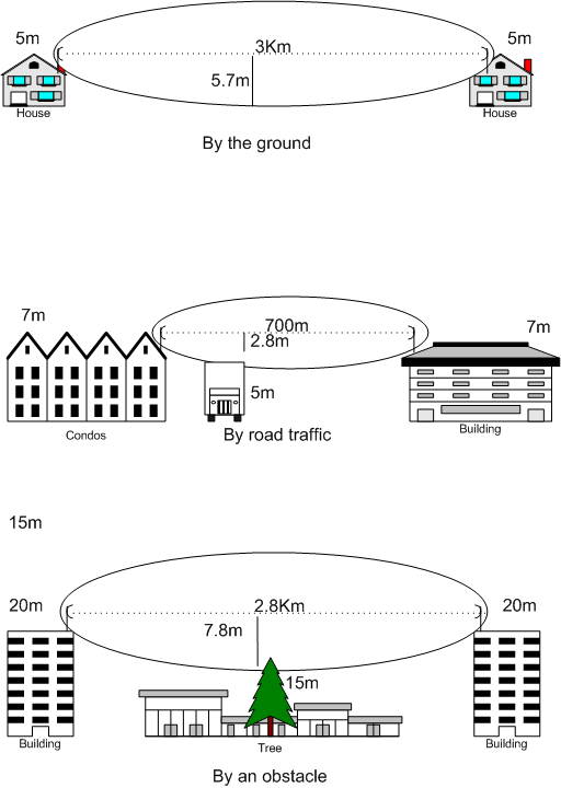
@alpine niche FYI I just did a really simple range test with 2 Lora RFM95 units: simple wire antenna ; receiver inside my house on my desk (on a Raspberry pi 3b+) ; the transmitter with a GPS and feather m0 express + rfm95 breakout -- I walked around my neighborhood. Lots of tress and houses - not a great line of sight and I got about 300 meters before losing the signal. I'm sure that can easily be greatly extended with a bit of effort.
These are the test units
hardly ideal conditions 😉
 restive fjord
that's 3/16ths of a mile. ;)
normal drift
yes it is.
restive fjord
That sounds great to me.
There's a lot of loss in transmission cable above (say) 120 MHz.
normal drift
the guide says 2Km is attainalbe with a wire -- needs unobstructed line of sight I would expect.
restive fjord
Mounting the unit on the top of the tower is usually going to be a lot better than using hardline transmisson cable, I'd suggest. ;)
normal drift
This was about what I expected - I'm happy with it.
restive fjord
The gunnplexer diode experimenters did hilltop to hilltop, where Line Of Sight was factual.
If I get 80-90 feet without worrying too much about obstruction in these Part 15 devices, I'm giddy with excitement.
I do hear distant neighbors on 802.11 (WiFi) but very sporadically.
normal drift
the LoRa (RFM95) does so much better then the RFM69
restive fjord

The larger the distance, the more obstructions between stations .. obstruct, due to the fresnel zone, according to wikipedia.
So you have to elevate the antenna even more than line of sight (laser) would require.
normal drift
my desk is only 30 inches off the floor 😉
restive fjord
Not clear if that fresnel zone applies below the microwave band all that much.
This is a nice article:
https://en.wikipedia.org/wiki/Fresnel_zone
When I move my DECT 6.0 base from one location to another in my apartment (entire ground floor) I get pretty big differences in where there's coverage.
My best coverage was with a system that Jabra made in the 1.2 GHz region. Telephone wireless headset that plugs in where a normal telephone handset does (and so adapts to many telephones).
That had a tiny battery, too.
normal drift
Thanks for the info -- I have to go AFK for a bit -- 73
alpine niche
@normal drift thanks for testing that! I'll try the ~73mm antenna first!
vocal veldt
@alpine niche I like using the LoRa antenna Adafruit sells, but I've yet to do a range test for fun
 tiny dust
https://cdn.discordapp.com/attachments/434855934016094208/511537514402676737/radio_block_diagram.png

[22:50] <hatsunearu> my only gripe is that 75MHz clock
[22:51] <hatsunearu> it's really bad because if i do a 15x CIC decimation, then the CIC passband is 1/5 which has tons of aliasing
[22:52] <hatsunearu> if i do 5x CIC then there is way too much work to be done with the FIR filter
vocal veldt
@normal drift I'm up to the AES implementation in tinylora, was wondering if you had one of the (aforementioned) resources on it handy
normal drift
@vocal veldt I started with this https://github.com/bozhu/AES-Python then stripped out decrypt -- here is what I was working on:

GitHub
A pure Python implementation of AES. Contribute to bozhu/AES-Python development by creating an account on GitHub.
encrypt only
normal drift
The aes_encrypt.py should run under CP using the examples from the original authors test.py
>>> master_key = 0x2b7e151628aed2a6abf7158809cf4f3c
>>> myAES = AES(master_key)
>>> plaintext = 0x3243f6a8885a308d313198a2e0370734
>>> encrypted = myAES.encrypt(plaintext)
>>>
>>> encrypted
75960790320075369159181001580855561010
>>>
@vocal veldt just recalled - the original code was for python 2 so it was important to fix the integer divides to use "//" not "/"
here are my diffs ```erryneedell@Ubuntu-Macmini:~/projects/AES-Python$ git diff
diff --git a/aes.py b/aes.py
index c569372..063c369 100755
--- a/aes.py
+++ b/aes.py
@@ -81,7 +81,7 @@ def text2matrix(text):
if i % 4 == 0:
matrix.append([byte])
else:
-
matrix[i / 4].append(byte)
-
return matrixmatrix[i // 4].append(byte)
@@ -106,7 +106,7 @@ class AES:
if i % 4 == 0:
byte = self.round_keys[i - 4][0]
^ Sbox[self.round_keys[i - 1][1]] \
-
^ Rcon[i / 4]
-
                ^ Rcon[i // 4]
           self.round_keys[i].append(byte)

           for j in range(1, 4):
@@ -216,4 +216,4 @@ class AES:
s[i][2] ^= u
s[i][3] ^= v
-
self.__mix_columns(s)
\ No newline at end of file
-
self.__mix_columns(s)
@normal drift the main difference I've found between how TinyLoRa does it and how that library does is within the sub_byte step and aes_encrypt step
normal drift
I did not get as far as trying to incorporate it into TinyLora so you may be well ahead of it at this point.
vocal veldt
probably not as far as they've been, but it's good to see two variations of how to perform the steps
thanks for the links. I'm actively working on it on the brentru/circuitpythontinylora master, have RFM reading/channel/country selection/datarate, etc...just need the encryption stuff and a lot of testing lol
normal drift
Great! I'll be happy to test whenever you are ready.
no pressure here -- I'm in no rush!
alpine niche
curious with using a connector for external antennas, would the cable running between the board and the antenna affect (effect?) the output of the signal?
... or I could do my own research
 trail acorn
(The arrow affected the aardvark. The effect was eye opening)
@alpine niche also yes, I believe it can however I think generally cables used for antennas are shielded (generally coaxial, I think) so that the conductor carrying the signal from the antenna is isolated from radiation until it gets to the antenna proper. I only half know what I'm talking about so perhaps an adult can chime in.
alpine niche
I think I need to dive into communications before diving to far into antennas
trail acorn
I mean, sure? There is some basic antenna info available targeted at prospective "tech no code" (or whatever the modern equivalent is) amateur radio operators.
I think ARRL probably has some publicly available resources
 static snow
@alpine niche @trail acorn A properly selected coaxial cable won't radiate much of the RF signal; it's designed for transmission. Short lengths of coaxial cable will introduce a small signal loss, but it won't substantially alter the behavior of the antenna. In most cases, slightly mis-sizing the antenna length would have a greater effect.
alpine niche
so adding a coax cable will slightly change the required size of the antenna?
alpine niche
915 MHz
restive fjord
L = f / 468 for 1/2 wave dipole (answer is in feet)
I got something wrong there
468/f ;)
(f in MHz)
alpine niche
I know its supposed to be 73mm just was curious, just starting to plan while waiting for parts
the area the sensors and such will be will be in a aluminum shell , so gonna need to get the antenna out
restive fjord
ex.
L = 468 / 27.115 = 17.2598 feet
It'll be an FCC Part 15 device at that frequency.
So, low power.
Your main design goals are correct operation of the electronics in the unit itself, and low losses in transmission and reception.
Possibly, shielding the unit from outside interference.
73 mm sounds like 1/4 wavelength antenna design

 restive fjord
78 mm * 2 = 156 mm
156 mm = 0.511811 feet
468 / 0.511811 feet = 914.4 MHz
That's a 1/4 wave whip
(I always calculate 1/2 wave antennas then convert from there)
alpine niche
thats what you mean by 1/2 wave... I feel slightly less intelligent for not getting that
restive fjord
This is the recommended antenna connection, for an external antenna
https://learn.adafruit.com/assets/31590
The only variable is the length of the coax. You can also pay attention to where the cable is 'dressed' inside the chassis.
Depending on the application it may possibly yeild a different result, depending on the length of that cable.
Radio waves are graphed as a sine wave.
If you know your signal is at 900 million cycles per second, you know what fraction of a second a single cycle occurs within.
I'm trying to remember this without looking it up.
3.5 MHz is the 80 meter ham band; 7.0 MHz is 40 meters.
alpine niche
so the band length and antenna length match?
restive fjord
Yes.
alpine niche
and what we refer to the band as?
restive fjord
For some reason the wavelength is the usual reference below 30 MHz.
When you get to the 2 Meter band (144 MHz) it starts to become easier to speak about the frequency.
440 MHz is called the 70 cm band; above that 'GigaHertz' is normal to refer to a band.
1.2 GHz band. 900 MHz band. Like that.
You could refer to the wavelengths instead, but the custom seems to be to speak in gigahertz when you get above 1 GHz.
Light people (lasers) deal in nanometers!
Probably because, say, 555 nm is easer to cite than the frequency of light at that wavelength.
X-rays and Gamma-rays people probably deal in energy (maybe in Joules?)
Yet they could cite frequency or wavelength and be talking about the same phenomena. ;)
So anyway, for a 10 meter dipole, 1/2 wavelength, it's
L = 468 / 28 = 16.714 feet
F = 28,000,000 Hertz (28 MHz) there.
That antenna operates on the 10 meter ham band (28 MHz).
A 1/4 wave vertical antenna would be exactly half of that length.
(8.357 feet)
alpine niche
Coming from a image processing background the amount of overlap is really interesting
restive fjord
A 5/8 wave whip would measure
16.714 * 2 * 5 / 8 = 20.89 feet or 250 inches.
alpine niche
Is there a reason for hitting 1/2 1/4 or 5/8?
restive fjord
5/8 is very nice.
Lower radiation angle if I recall correctly. It is a vertical antenna.
Also used for mobile on 2 meter band. Larsen makes a nice 2M 5/8 wave mag-mount antenna for the roof of your car.
1/4 wave is kind of a traditional vertical whip antenna.
alpine niche
and 2m is HAM correct? for audio?
restive fjord
2 meters is 144 MHz amateur radio band and covers all modes. Voice, morse code, digital.
It's 144 to 148 MHz (exactly) and the MARS band is just above it.
1/4 wave antennas are favored for their small physical size; I have one for a 2 meter handheld radio.
If you need a physically shorter antenna sometimes you can include a loading coil at the base of the antenna, or add one to the middle of the antenna (and probably in several other locations along the antenna -- choosing just one location for a given design).
Conversely (if I have this correct) you may need a capacitance "hat" on the very end of the antenna, to add capacitance -- I think this electrically shortens an 'over-long' antenna.
Some of the early hats looked like shamrocks. ;)
alpine niche
curious then, is the circuitry what dictates 1/4 vs 1/2?
restive fjord
There is often a final amplification stage in a transmitter, in addition to earlier (lower power) stages.
The PA (power amplfier) may be matched to the antenna in more than one way.
A Pi Network was used as the tank circuit in tube-type transmitters of modest power (100 Watts).
The Pi Network consists of two capacitors (usually large air-variables) and one coil (equally large).
They form the shape of the letter pi
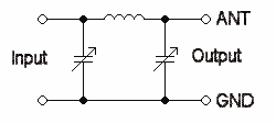
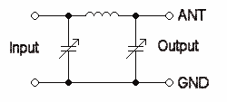
(imagine the ground wire missing - the remaing part of this diagram forms the letter pi)
The Pi Network is very robust in that it will successfully match the impedance of a very wide variety of antennas, to the PA, such that there is good power transfer to the antenna.
Transistorized finals (final amplifier; PA) do not typically use a Pi output network.
By themselves they match fewer antenna designs and impedances than their more robust cousin.
as far as I know, anyway.
Most antenna experimenters (or at least some of them) judge their antennas using an RF power meter, an SWR bridge, and some types of antenna evaluation circuits that power the antenna with a sample radio signal (usually rather low power; perhaps battery operated).
I think the old school method was called a grid-dip meter.
test 1: does the attachment of the antenna destroy the transmitter?
test 2: can the transmitter signal be heard at the receiver, far from the antenna?
test 3: does the radiated signal interfere unintentionally with anything else that is not part of the system?
If you pass test 1 and test 2 you have a functioning system.
If you (optionally) also pass test 3 you have an 'amicable' system. ;)
If you are operating in Part 15 then test 3 is essentially hand-waved for most uses.
(nobody knows/cares/can do anything about you)
alpine niche
this particular project * shouldn't * have anyone near it to interfere with
I guess I could go out with the SDR and scan everything
vocal veldt
@normal drift ha, weirdness in the tinylora library...It performs another key creation within the round instead of just going through the round normally and adding to the roundkey

GitHub
LoRaWAN Library. Contribute to adafruit/TinyLoRa development by creating an account on GitHub.
¯_(ツ)_/¯
oh, the other AES lib generates the keys for the round before entering the round
normal drift
not sure I see the problem
vocal veldt
@normal drift oddly after that re-calculation, add_key step will produce an incorrect key (inconsistent with the tinylora lib)

GitHub
LoRa and The Things Network - with CircuitPython! Contribute to brentru/Adafruit_CircuitPython_TinyLoRa development by creating an account on GitHub.
It's really close, but not exact, and that'll mess up each subsequent round...thinking
normal drift
do you need this step? https://github.com/brentru/Adafruit_CircuitPython_TinyLoRa/blob/master/aes_impl_wip.py#L101
GitHub
LoRa and The Things Network - with CircuitPython! Contribute to brentru/Adafruit_CircuitPython_TinyLoRa development by creating an account on GitHub.
just a sec
I don't see that in the AES lib -- in round_key_encrypt
vocal veldt
GitHub
LoRaWAN Library. Contribute to adafruit/TinyLoRa development by creating an account on GitHub.
It's part of the TinyLoRa AES procedure, the AES library pre-calculates those values
normal drift
yes in encrypt - but not in round_key_encrypt ??
vocal veldt
I think the add_round_key performs that, since it takes in the predetermined key matrix
normal drift
I may just be confuses, but I think there is an extra step in you round_key_encrypt ... still reading.
vocal veldt
Yep, I added in aes_calculate_key
normal drift
right -- does taht cause a problem?
vocal veldt
Doesn't seem like that's the issue
normal drift
ok - thats waht I was looking at
vocal veldt
TinyLoRa:
state: 669993124999999999999999999999999
STEP: Add_Round Key: Round Key: 98999999989999999899999998999999
state: 3206231100010001000
TinuLoRa CPy
Round Key:
98999999989999999899999998999999
state:  [[66, 99, 93, 124], [99, 99, 99, 99], [99, 99, 99, 99], [99, 99, 99, 99]]

STEP: Add Round Key
Round Key:
98999999989999999899999998999999
state: [[32, 1, 63, 30], [0, 0, 0, 0], [0, 0, 0, 0], [0, 0, 0, 0]]```What's strange is the first time that add_round_key occurs (way back in aes_encrypt) - it doesn't cause an issue.
normal drift
aes_calculate_key -- changes key
vocal veldt
AES (Rijndael) uses a key schedule to expand a short key into a number of separate round keys. This is known as the Rijndael key schedule. The three AES variants have a different number of rounds. Each variant requires a separate 128-bit round key for each round plus one more...
normal drift
OK -- I need to look much more cloesly at the two implmentations to follow
Will try to dig in, but may not be able to get to far before Friday -- Hopefully -- you'll have solved it by then!
vocal veldt
Hopefully
once I get this first round done, subsequent rounds will fall into place, which is good
normal drift
domino theory ...
vocal veldt
I feel it has to do with the left rotate of column in that tinylora round_key add..
normal drift
side note -- shoulde this be "//" https://github.com/brentru/Adafruit_CircuitPython_TinyLoRa/blob/master/aes_impl_wip.py#L166
GitHub
LoRa and The Things Network - with CircuitPython! Contribute to brentru/Adafruit_CircuitPython_TinyLoRa development by creating an account on GitHub.
I guees it is handled by int() -- could just use I think
sorry -- I have to go for awhile -- good luck -- I'll try to study it later.
vocal veldt
I think I figured it out, the addressing to the Sbox needed to be stricter (the aes impl. you sent me had it as a 1d list, but I need to address [row][col]
I'm going to refactor the sub_bytes function tomorrow to reflect the change, and remove it, it'll be more towards the aes_sub_byte in tinyLoRa's impl.
tiny dust
:\
 frozen zealot
Has anyone had the RX component inside a Feather 32u4 break on them?
I have a strange issue where I can send UART data to my phone using the adafruit app, but can't receive from my phone
vocal veldt
@frozen zealot nope! post up on the forums
@normal drift are you around? I got the rounds of AES going, but keep hitting up against an issue
@frozen zealot https://forums.adafruit.com/viewforum.php?f=53
normal drift
@vocal veldt I’ll be tied up for the next hour or so. Post a link to the issue and I’ll take a look when I can.
normal drift
@vocal veldt free for a little while now if I can help
vocal veldt
Think I got it, thanks!
normal drift
Great! Even better!
vocal veldt
😄
rounds look good, time to move 'er into the library (fingers crosed that I dont explode)
alpine niche
Successfully got them talking at least
alpine niche
Slightly worried at my apartment in the city, I can't get reception on the other side of the window. Hope these antennas live up to the 1/2 km I need on the farm
 primal warren
I used to work in a building that apparently had windows with some sort of conductive coating (vacuum sputtered aluminum to reflect heat? I don't know) that blocked radio waves fairly effectively.
alpine niche
thinking about it.. we have terrible cell reception despite being right near several towers
frozen zealot
Figure I'll post here on top of the forums, but I have a Bluefruit Feather M0 that is running the same program as a Bluefruit Feather 32u4. For some reason, when I send power to pin 11, the bluetooth connection drops 😐
 glad nebula
Looking for the BLE command to re-initiate communication with a paired device. I now have the CPX connected to the BLE Friend SPI and paired successfully to my phone. Also the Adafruit BLE app works with it. However, using the demo code , once the connection is broken, it will not reconnect. Other BLE device I have will re-initiate a connection to my phone after initial pairing and my phone restarted BLE connection. Anyone know what the command I need to do this is? Examples are golden 😃
glad nebula
The example code I am using which works to pair the BLE is https://github.com/adafruit/Adafruit_CircuitPython_BluefruitSPI/blob/master/examples/bluefruitspi_simpletest.py
GitHub
Helper class to communicate with the Adafruit Bluefruit LE SPI Friend in CircuitPython - adafruit/Adafruit_CircuitPython_BluefruitSPI
glad nebula
It looks like "if not bluefruit.connected:" is not working correctly. If I turn BT off on my phone, the SPI Friend keeps the blue light on, and it never breaks. So, whatever bluefruit.connected is doing, it's not checking the connection to central....
glad nebula
Ok, so I used the serial out to confirm that both bluefruit.connected and the AT command bluefruit.command_check_OK(b'AT+GAPGETCONN') both show that the SPI friend is connected , even after I turn my phone BT off. I DID find that I can force the module to disconnet using bluefruit.command_check_OK(b'AT+GAPDISCONNECT'). However this also means my phone has to re-pair with the device in order to connect again. There must be a way for a paired device to reconnect...right?
glad nebula
Also, FW updated to 0.8.0 , but device page only goes up to 0.7.7 😯
glad nebula
@harsh token ok, yup..8 mos old. But really what I want is a way for the SPI Friend to connect...AFTER it is already paired (like other BT devices do).
And also , the bluefruit.connected thing is strange to me.
 harsh token
I'd have to look at the library's code... The nice part with Open source, is that everyone has access to the best manual around: the code itself 😃
Who knows? Maybe in <bluefruit.connected> connected means paired and link established?
If the link falls asleep, it is still "connected", but inactive...
vocal veldt
@normal drift good news - it's close
finished up aes, almost done with MIC but I'm hitting an issue at the last step it takes and I'm not sure where it's failing, I have to black-box the arduino version's function calls for this a bit more
normal drift
Sounds like great progress. I won’t be able to access any HW until Sunday but will look at code as time and grandkids allow 😉
vocal veldt
I was worried about the MIC, since it HEAVILY relies on the AES methods. I've fixed a few of them up as a result though, which is good.
glad nebula
@harsh token Right...I'm hoping someone else here knows how to use this device and what it's capabilities are, as I go through the pdf and all the AT commands. I've gone through them a couple of times and don't see too many options. It really looks like this device was set up for demos or brief use cases.
vocal veldt
@normal drift should be a green flag if ya wanna try testing it (I haven't done any RTL-SDR scoping yet, but the MIC and AES implementations are 1:1 with arduinos, fixed up a buncha other code too)
normal drift
@vocal veldt thanks. I won’t be able to do any testing until Sunday but will try it as soon as I can.
 surreal fulcrum
anyone have used ANT+ protocol?
surreal fulcrum
ANT is a Wireless Personal Network protocol, by Dynastream Innovations Inc., with small size, reasonable cost and Very Low Power requirements.
hmm speaking of what and new  product using that one nordic semiconductor chips https://www.thisisant.com/developer/components/d52
ANT is a Wireless Personal Network protocol, by Dynastream Innovations Inc., with small size, reasonable cost and Very Low Power requirements.
glad nebula
Still hoping to find some answers a out this SPI Friend module. I tried testing RSSI using print(bluefruit.command_check_OK('AT+BLEGETRSSI',delay=2)), and though I get seemingly valid responses in the -57 to -68 range or so....it keep reporting that AFTER I turn off the BT on my central device. That does not appear to be doing what it's supposed to, per documentation. Again, still no way to check actual connection to central device with provided commands.
normal drift
@vocal veldt started playing with your code - I get it to send a packet, but I am not receiving it at TTN -- Do I need to do more than the configuration (with my keys) in your simpletest then issue a lora.send_data(data,4,0)
normal drift
@vocal veldt woohoo! -- it is working - sending packets to TTN -- nice work!
vocal veldt
@normal drift nice! I just updated the branch to reflect your changes, new gateway isn't seeing the node..checking
normal drift
@vocal veldt any luck seeing packets?
vocal veldt
nope
normal drift
hmmm -- I'll download the new version and try this evening
vocal veldt
i just set up this gateway though, might be something different with it
normal drift
ah -- lots of variables 😉
vocal veldt
mhm got it, it was the gateway having issues with my WEIRD network
normal drift
@vocal veldt FYI -- just downloaded your branch and something is broken -- my gateway sees the packet, but it does not get to the device on TTN any more.
vocal veldt
@normal drift the device/application doesn't show it?
normal drift
right --
vocal veldt
hm, same.
normal drift
ah -- reverted to previous tinlylora_encryption.py and it works ... looks like pylinting broke something...
new adafruit_tinylora.py and old tinylora_encryption.py works
vocal veldt
Okay...I was checking against the gateway while I pylinted and submitted. Going to be checking against the device now to ensure it doesnt break
thanks for the alert
normal drift
N problem -- getting close!!
vocal veldt
YEAH, the pylinting of this is going to take some time/refactoring
then release n'guide 😄
normal drift
@vocal veldt new version works!!! -- I found the issue with self.frame_counter -- in tinylora_encryption.py you used self._frame_counter ...
vocal veldt
@normal drift changing to see if that fixes...
normal drift
my quick test did not work -- only gets frame_counter == 0
I think I misunderstood -- in tinylora_encryption self._frame_counter private -- not the same as self.frame_counter int adafruit_tinylora.py -- not sure why it was done that wasy, but it still needs to be set in adafruit_tinylora.py
in which case, no change needed
vocal veldt
@normal drift Not sure I follow. adafruit_tinylora passes the current frame counter into adafruit_tinylora_encryption when it calls encrypt().
normal drift
right -- and then in tinylora_encryption -- you use a local private variable self._frame_counter -- that works fine.. I was confused.
It works as is.
vocal veldt
Ah, I thought you were talking about the error the pylinter tosses regarding frame_counter 
normal drift
no -- I did not look at pylint -- there may be another way to handle frame_counter, but if it ain't broke .... at least for the initial release 😉
right now your branch is working fine!
gatta go make a pizza -- more fun later
normal drift
@vocal veldt updated to latest -- working on itsybitsy_m4_express and feather_m0_express.
vocal veldt
nice!
normal drift
@vocal veldt looks like you har having fun with lint! good luck!
vocal veldt
it's a lot of lint, reminds me of the laundrymat 😆
considering adding in a TTN class that'll hold the country/channel/keys tbh
lora = adafruit_tinylora.TinyLoRa(spi,cs,irq,devaddr,nwkey, app, country='US') is a huge constructor
maybe something like lora = adafruit_tinylora.TinyLoRa(spi,cs,irq,ttn)
normal drift
I like that!
vocal veldt
then, ttn_config = ...TTN(dev_addr, network_key, app_key, country, channel)
for the class init
normal drift
I also found it easier to enter the keys using key = bytearray([0x00,0x00,.....]) rather than the (b"\x00...) -- easier to cut/paste from the TTN site.
normal drift
just have to rplace the "{}" with "[]"
using "{}" in python causes some weird issues!
vocal veldt
yep. I might shoot TTN an email about that.
i.e: code button can go to python/arduino
primal warren
In Python, {} creates a dict, and [] creates a list: they're both collections of objects, but they aren't the same!
vocal veldt
https://github.com/TheThingsNetwork/ttn/issues/749 @normal drift I posted a request on their repo for visibility
GitHub
Hi TTN Team, I'd like to request a feature on the web console for applications which would allow for easy inclusion of Python-nodes, in addition to C/C++ based nodes. In Python, { } creates a d...
normal drift
@vocal veldt in https://github.com/brentru/Adafruit_CircuitPython_TinyLoRa/blob/master/examples/tinylora_simpletest.py#L28 I thik you need to increment the frame counter.
GitHub
LoRa and The Things Network - with CircuitPython! Contribute to brentru/Adafruit_CircuitPython_TinyLoRa development by creating an account on GitHub.
vocal veldt
adding it back. to example, tested ok
normal drift
actually don't "have to " increment it -- since checking is disabled, but I think it should increment.
vocal veldt
same
normal drift
and for actual release - I think the delay should be much longer -- like 30 sec -- 1 sec is a lot of traffic!
vocal veldt
yeah, this is just testin', probably 30s to match TinyLoRa ARduino
normal drift
@vocal veldt This looks like fun - https://www.thethingsnetwork.org/conference/#1465929924365-86a6e8da-68a2a255-414b
 vocal veldt
@normal drift I know, I'd need to get a passport though...and it's past their CFP :\
(in before @rapid hearth makes a joke about the company hovercraft again)
 grand acorn
cool there's a radio channel! 😃
Is anyone else working with TI CC1101 equipped RF antennas?
I don't have a specific question, everything's going fine so far but it would be interesting to know
primal warren
I've worked with a couple of TI's other CC series devices (mostly WiFi and BLE), but not that one in particular.
I did start reverse engineering a device that used a CC1020 a while back.
vocal veldt
alright, updated the lora lib with a ttn configuration class, more after 🍴
normal drift
@vocal veldt tried latest on RPi and ItsyBitsym4 -- worked fine -- just had to import TTN as well as TinyLoRa
vocal veldt
yeah, im getting to raspi...slowly
I have the Gateway bonnet from last month that I'll test it on
normal drift
after fixing the MIC issue, RPI has been no different than CP
vocal veldt
yay
normal drift
I just have aLoRa Featherwing on the Raspberry Pi. It's been working well.
grand acorn
Hey guys, maybe someone can help me with this :D
I've read out the OOK code of my 433MHz wall outlets and was able to turn them on / off with the CC1101 and the Arduino Uno.
Now after getting a python library running on the M4 Express (circuitpython), somehow they don't react.
This is the working and not working signals:
vocal veldt
Requesting a code review of https://github.com/adafruit/Adafruit_CircuitPython_TinyLoRa/pull/1 if anyone wants to take a look
grand acorn
the recordings both aren't very clean but that's just because I set the receiver to 433MHz.
Unfortunately I'm not able to remove that preamble on the bottom image (using the Python library), so I added a bit of "zeros"
still, it doesn't want to accept it, so maybe I'm missing something here 😄
normal drift
@vocal veldt will take a look and do some testing. May not do able to do much before Friday.
vocal veldt
@normal drift sounds good, I don't have fresh eyes on this library anymore since ive been working on it for a while (and it's pretty large), that'll be helpful.
grand acorn
yup it's that preamble.. 🤔
normal drift
@vocal veldt downloaded pr_1 -- runs as before on RPi and itsybitsyM4 -- still can't run it from a n adfruti_tinylora folder but from root folder it all runs fine. I'll try to review the code in the next few days. Thanks for all the work on this.
glad nebula
Still looking for feedback on "connect" and "RSSI" functions for BLE Friend SPI module....
normal drift
@glad nebula I hope to have some time this weekend to try to reproduce and explare this issue. Will let you know how it goes.
vocal veldt
@normal drift interestin idea i had
instead of loading data directly into the data array as bytes, maybe i should add a method for sensor data into tinylora...
eh, might make the library larger than it needs to be...
normal drift
@vocal veldt Thats is an interesting idea, but I think it best to leave the data packet construction up to the user. Who knows what "sensors" there could be. I like it being just "send these bytes for me please" 😉
I do wonder if we could simplify the frame_counter business and have tinylora do the incrementing - but allow it to be set as a keyword argument if desired.
vocal veldt
maybe these are "v2" features 🤷
normal drift
agreed!
vocal veldt
Most LoRa libs (i've looked thru a bunch of them, incl. LMIC) leave the frame counter up to user control
since we're disabling it (for ABP sends), it doesn't really matter
normal drift
Thats fine -- I like user control 😉
vocal veldt
@normal drift frame counter is handled by the lora_frame_counter, not init'd?
re: your PR initalize and increment
normal drift
in you exampl, you are using lora.frame_counter as the input to send_data -- shouldn't taht be a local user variable.
vocal veldt
GitHub
LoRaWAN Library. Contribute to adafruit/TinyLoRa development by creating an account on GitHub.
ya, AES kinda modifies the frame counter...checking...
nvm, it just uses it
normal drift
I think that example is fine -- it should be incremented by the user -- it is not in your si7021 example.
vocal veldt
adding a new one
normal drift
Thanks!!
vocal veldt
np
alpine niche
As someone who recently dived into lora, it was nice to be able to build my own data packets. Although Im tempted to make a library for CoAP packets for end point to end point
glad nebula
@normal drift Great! Thanks much. I'm pretty much stuck as it is now with the AT commands I see provided. I do see there are more in depth AT commands that can change some settings per BLE spec, but not sure what those might be exactly.
normal drift
@glad nebula Have you looked at this example? https://github.com/adafruit/Adafruit_CircuitPython_BluefruitSPI/blob/master/examples/bluefruitspi_ruggedechotest.py I may be misunderstanding what you need, but it is able to detect and report the connection status and it drops the connection if I turn off the phone.
GitHub
Helper class to communicate with the Adafruit Bluefruit LE SPI Friend in CircuitPython - adafruit/Adafruit_CircuitPython_BluefruitSPI
@still heart Nice update to the issue --lot of good information. thanks -- oops wrong channel
@glad nebula It looks like this is the key command https://github.com/adafruit/Adafruit_CircuitPython_BluefruitSPI/blob/master/adafruit_bluefruitspi.py#L218
GitHub
Helper class to communicate with the Adafruit Bluefruit LE SPI Friend in CircuitPython - adafruit/Adafruit_CircuitPython_BluefruitSPI
grand acorn
Hey guys, I'm working on a driver for TI CC1101 antennas and while I'm able to transmit nicely, something must be off in my settings regarding RX.
When there's clearly no signal sent in the room that I'm in on the specific frequency, the antenna board reports that it received data etc.
Maybe if someone has worked with those before he can give me some hints regarding carrier sense settings etc.
glad nebula
@normal drift thanks for the response. Yes, I've been using that original example to test. As stated before, I've noticed 2 things; 1) That code does not appear to be working to test connection to central device as written, and 2) I cannot use those commands to check connection or RSSI level. Still trying to get this to work, and not familiar with placing device in "command mode" with "+++". That is also not working for me. Still working on it....
normal drift
@glad nebula if you want tor post an example of code you are trying to run, I'll be happy to try it. The examples do work for me and I can check the RSSI.
glad nebula
@normal drift It's pretty much the same as the example you pointed me to, and I've tried lots and lots of things to get it to work. Also, finding it errors out frequently with "RuntimeError('Timed out waiting for a response.')
Also, I'm a noob to discord and cannot post the code.
normal drift
you can just hit the "+" key and select the file or post it between 3 backticks the lowercase of the tilde on a US keyboard your code here
glad nebula
ok
normal drift
last night I hooked up a Bluefruit UART friend to my CPX -- only needs 4 wires!! It worked well. I'll reconnect the SPI friend tonight and try some tests.
glad nebula
Ok. I need to spend more time with this. Basically I can get it to pair, every time, very quickly. What I cannot do is get it to detect when the connection is broken. The Blue light on the module just stays on when I turn my central device BT off. Also, I am trying to use the "+++" command to put it in command mode (not sure what the difference is between doing that and just using the commands directly). In Python I am just using teh command_check_OK....is that not a "command" or in "command mode" ?
normal drift
how are you pairing with it - what app do you use? Are you pairing classic BT or BLE ?
glad nebula
On my phone, I turn BT on. The only way I can get it to connect with the BT Friend is to pair it. Once it's paired the Blue light on the BT Friend turns on, but the RSSI or connect commands do not appear to work, or report a valid state. I can enter the disconnect command and the blue light turns off, but then I have to re pair my phone again.
normal drift
I don't pair via BT -- I use the adafruti BLe app https://github.com/adafruit/Bluefruit_LE_Connect_v2
GitHub
iOS app for use with Bluefruit Bluetooth LE modules and dev boards from Adafruit (v2.0) - adafruit/Bluefruit_LE_Connect_v2
glad nebula
In looking for the disconnect, I modified the example code as follows if time.monotonic() - connection_timestamp > 3: connection_timestamp = time.monotonic() print(connection_timestamp) # print(bluefruit.connected) # print(bluefruit.command_check_OK(b'AT+GAPGETCONN')) # bluefruit.command_check_OK(b'AT+GAPDISCONNECT') if not bluefruit.connected: break
Anyway, I need to try a few more things.
Ok, Ble app....not sure if that would be different, I can try that too.
normal drift
I'm still new to thsi stuff, but I think pairing wit BT is different than using BLE .
glad nebula
ok
I thought modern cell phones were BT and BLE compliant.
In fact, I notice 3 different connection icons on different BT devices, (looks like music, data and something else)
normal drift
yes, but BT and BLE are different protocols and the commands are for BLE, not BT.
a device may support both BT and BLE, but BLE can't talk to BT, unless I am mistaken.
glad nebula
Ok, but I'm not issuing any commands to or from my phone (save for the BLE Friend). If my phone is BLE compliant, it should know what it is talking to methinks. Maybe not, but it DOES know when it is connected (and connects very quickly), it DOES NOT seem to know what the RSSI and connection status is, which seems like an issue with the BLE Friend, or how I am using it.
normal drift
hmm -- OK -- I'lll try to poke at it more tonight or tomorrow when I can play with the HW.
glad nebula
Oh, also, I was able to use their "Bluefruit LE connect" and even updated the FW on the module.
normal drift
right -- but try kust connecting with the BLE connect app -- not pairing via BT
glad nebula
But it looks like that app was made for another device using arduino examples so did not really work for most of the fuctions. It DID upgrade my device though.
normal drift
just use the UART connection with the ruggedecho test.
normal drift
I have gotten the echo (uart) and the colorpicker controls to work.
glad nebula
kinda hard to use here...we have about 50 BT devices in my area...makes app slow on loading device list 😦
And the filter is still slow, as it filters out devices.
Actually, we probably have more like 100 BT devices near me.
normal drift
make sure your BT is unparied
glad nebula
Yeah, it connects. Not sure what UART echo is doing. You mean I should be running that demo code to send back echo data?
Getting the code to run what the BLE is connected and using the app is a bit of a juggling act. The code errors out frequently, and the BLE module takes a min to connect.
normal drift
rune the demo code the opne the UART screen in the app -- type some stuff and it should show up on your REPL and echo back reversed.
hmm - what errors?
glad nebula
ok, just have to get it in the right order. Code running, BLE connected, UART in app open...
If I type "test" in UART window on app...no response in window or python console window.
Just says "No data"
    print("\n *Connected!*")
    connection_timestamp = time.monotonic()
    while True:
        # Check our connection status every 3 seconds
        if time.monotonic() - connection_timestamp > 3:
            connection_timestamp = time.monotonic()
            print(connection_timestamp)
            # print(bluefruit.connected)
            # print(bluefruit.command_check_OK(b'AT+GAPGETCONN'))
            # bluefruit.command_check_OK(b'AT+GAPDISCONNECT')
            if not bluefruit.connected:
                break

        # OK we're still connected, see if we have any data waiting
        resp = bluefruit.uart_rx()
        if not resp:
            print("No data")
            print(bluefruit.command_check_OK('AT+BLEGETRSSI',delay=2))
            continue  # nothin'
        print("Read %d bytes: %s" % (len(resp), resp))
        # Now write it!
        print("Writing reverse...")
        send = []
        for i in range(len(resp), 0, -1):
            send.append(resp[i-1])
        print(bytes(send))
        bluefruit.uart_tx(bytes(send))

print("Connection lost.")```Blue light is on.
and....code errors out with "Unknown response" after about 40 seconds.
normal drift
if you disconnect the app -- it should go off. -- try setting EOL characters to /n/r and enable EOL
I have them st that way for some other boards and not sure if it is necessary but wont hurt.
on the UART scree there are options to set EOL
are you using the IOS or Android App?
glad nebula
android. I can try those settings.
normal drift
I have used the android app as well -- should work -- but it'll be easier whenI can be hands on. Does the code report the connection in the REPL?
glad nebula
wow...that worked! /n/r seemed to get data back too.
normal drift
yay!!
glad nebula
unfortunately, code errors out again after a min.
Looks like if the response it not what is expected , it just throws and error and the code crashes.
normal drift
hmm - I have not seen that. this is the "ruggedecho" demo code?
glad nebula
So, one small step, but all I really want is for the module to detect the connection to my phone. Since it CAN connect, seems like there should be a way to toggle this connection and test it.
I am just running the code posted above (after it is connected), the simple echo test code running on the CPX.
normal drift
the code should report the connection status if you connect/disconnect
glad nebula
nope
normal drift
GitHub
Helper class to communicate with the Adafruit Bluefruit LE SPI Friend in CircuitPython - adafruit/Adafruit_CircuitPython_BluefruitSPI
glad nebula
At least not with the normal pairing method I did before. It might work with the app...but the code crashes too quickly (with unexpected response) before I have tried that yet.
Appears to do the same thing. Blue light stays on after I turn my phone BT off...so does not detect loss of connection. Also, code looks basically the same.
normal drift
don't use BT --
glad nebula
ok...ok...:)
normal drift
just use the app to connect/disconned -- make sure BT is unpaired
glad nebula
trying...app is super slow when you have lots of devices around.
At work, so we have about 200 BT modules around me. 😦
normal drift
make sure the blue light id off when you start the app.
normal drift
ok -- then disconnect and light should go off and REPL should show discnnect
glad nebula
please define "disconnect"
normal drift
exit the app or just back out screens untill it shows you the avaialble devicesagain.
or turn off your phone 😉
glad nebula
app is really hanging up on me...running really slow with all these other modules around.
It did disconnect, but all I did was touch screen, so trying it again..
normal drift
if you go back the the initial screen shere the devices ar listed, it will have disconnected from the Bluefruit -- then you can reconnect again
glad nebula
Ok, so connected, UART test worked, close app and Blue light shuts off.
glad nebula
I would really like a programatic way of connecting and detecting the disconnect. Am I hoping for too much?
yes, code still running now shows looking for connection.
normal drift
not at all -- you jsut have to use the example in the code if not bluefruit.connected:
glad nebula
Also, filtering with "Must have UART Service" in app works to kill all the other devices.
normal drift
ah yes -- I should have thought of that!
glad nebula
ok, so if not connected then issue connection command?
I removed the header init_bluefruit so it doesn't do the factory reset or rename the device.
That seems to work fine.
I just need to get it to reconnect.
normal drift
well -- it depends on waht you want to do -- bluefruit.connected just tells you the status.
glad nebula
There should be something to tell it to connect. Or is that initiated only from the Central device? That doesn't seem right because I am aware of other BT devices that connect to my phone when I turn them on (previously paired, and auto connect).
Heck, even my car auto connects to my phone .
normal drift
in the code example -- if it is not connected, it re-initializes the connection by calling init_bluefruit()
again be careful BLE is not BT....
your care examples are for paired BT devices -- that is not what this code is doing.
glad nebula
ok
normal drift
This code example tell you when it is connected or not -- can you modify it to do what you need.
but it is not listening for your phones BT connection -- maybe that is the confusion.
you want it to autodetect when you enter the room?
but you are correct -t he Central device initiates the connection . the peripheral just advertises its availabliltly.
glad nebula
Ok, so code works to detect disconnect and re-establish connection. But I did the test by closing the app and re-opening the app, which also requires more button presses to find device again (in my mind that is just like pairing). I am going to try walking out of range and back in to see if that works now....
normal drift
it should -- good luck!
normal drift
sure -- if you lose the connection it should detect that.
ah -- but eh app may also disconnect -- in which case you are stuck 😦
glad nebula
Yeah...I had to go more than 60 feet away to get the disconnect, and it is not connecting now that I am back. 😦
normal drift
right - the app disconnected -- so you have to manually reconnect.
sorry -- need a new app 😉
glad nebula
that's just like pairing though. Seems like there should be another way, since other BT devices auto connect, why not BLE?
Methinks the "connect" button on the app is really "pairing"
reopening app and pressing "connect" , code still working and detects connection.
normal drift
Now I have a much better understanding of what your are truing to do. It may well be possible. Perhaps there ore otheres more familiar with BLE out there. At leas the HW and SW are now functioning as expected.. Maybe not as desired....
glad nebula
Yeah, so the code part of resetting the device and looking for a connection works. That's about half of the way there. 😃
I just don't want to have to touch my phone. Like other "paired" devices it should work with the BLE module is turned on.
normal drift
yup -- good luck! also of this has to do will the roles centrals and peripherals. Right now the central (phone) is not cooperatinig.
the phone has to be doing something to look for the advertisement from the peripheral - I think you need an app that does that and automatically connects when it sees your peripheral. I don't have such an app, but there may be one out there....
glad nebula
Why do other things that are paired to BT automatically connect then? Isn't that the definition of "being paired" . My car connects, my headset connects....
normal drift
this is BLE not BT 😉
glad nebula
So BLE is like a subset? I need to understand that a bit more.
I also may try this with Wifi.
normal drift
it's completely unrelated to BT --- some HW support both but they are different.
glad nebula

Want to know which wireless technology you should use for your M2M idea?
normal drift
I was just going to post that 😉
glad nebula
We have a few in house experts I am going to ping today about this. Will let you know what they say.
normal drift
Great - thanks
@glad nebula I don't want to give the impression that BLE can't do what you want. I just don't know how to do it .. yet... I expect it can be done. At least I am glad to see that your devices and mine are behaving the same now... much easier to compare notes!
glad nebula
@normal drift Per the first in house expert, he confirms that BLE should behave like BT and I should be able to autoconnect. In house apps have done that with BLE. So, now hoping to find a way to get this module to do it. He did specify that getting the central device address is key (which is also a feature AT command of this module). Not sure what to do with that, though, once I get it, in order to advertise. So yes, any device in your paired list on your phone is being scanned for an advertisement.
normal drift
@glad nebula sounds promising, but I think the issue is on the Phone app side -- not so much on the device side. at least thats how it looks to me. the devise is advertising whenever it is disconnected.
glad nebula
Sheeesh...the BT core spec is over 2k pages....fun stuff
grand acorn
Hey guys, I'm still working with my TI CC1101 antennas and currently trying to receive data from an off-the-shelf RF remote.
I'm using its "asynchronous" mode where it just puts the demodulated value (high or low) on a specific pin that I can read with my Feather M4.
What is the recommended method for reading a pin in such a scenario?
I mean, should I try to read it at around the baud rate of the signal or maybe "busy wait" until it switches from 0 to 1 or 1 to 0 and measure the time that it has been in each state, something like that?
 arctic cloak
oh man... get a logic analyzer... saleaelogic saved my bacon many times.

Saleae has updated their popular Logic analyzer series to now include analog capabilities. A logic analyzer is a device that lets you watch digital signals in your electronics project, ...
grand acorn
Thanks for the recommendation, but even if I did have one: The question was if I should read the pin in a certain time interval or if I should do something else.
primal warren
There are a couple of ways to do it. Read it periodically and try to figure out the synchronization, or run a timer, and have the input generate an interrupt when it changes, and have the interrupt service routine squirrel away the timer value (many IR receiver programs work this way).
 heady wind
Hello! I bought a 433 MHz – Adafruit RFM95W LoRa Radio and then I bought a compatible (for that MHz) antenna, Can somebody help me on how connections has to be welded? Here there are some photos:
Antenna
Adafruit RFM95W
Cable to he welded
I see that the RFM95W has 3 space in which it is possible to weld an antenna while the antenna cable has only 2 cable (white and grey)
Can somebody help me? Thank you!
primal warren
On the RFM board, the antenna connection is the three gold pads in the lower right corner.
The small center pad is the signal pad, it goes to the center wire.
The two outer pads are both ground, solder the shield to one of those.
heady wind
so, the center gold on the board goes with my white cable?
and the gray one goes with one of the other 2 connection on the board?
primal warren
Right
heady wind
Thank you!
primal warren
Happy to help!
heady wind
Do you know how to wire the board with raspberry pi?
primal warren
Looks like the usual SPI type connection: hook SCK, MOSI, and MISO to the corresponding pins on the raspberry pi. You'll also need to hook up Vcc and ground, and choose a GPIO for chip select.
Unfortunately, I'm heading out for a while and don't have detailed instructions.
normal drift
@heady wind are you planning to use the CircuitPython rfm9x or tinylora library with it ( along with adafruit_blinka)? if so, then your Chip Select can be any GPIO pin EXCEPT CE0 or CE1.
If you are using another library, then the Chip select should usaually be CE0 or CE1
you also will need to use GPIO pins for the G0 interrupt and possibly the RST line depending if they are used by your code. Some libraries use additional Interuupts as well.
I aslo have to head out for awhile -- good luck!
grand acorn
@primal warren so method 1) would be: read at high speed until I get a "high", continue reading until it's low and high again, and then divide that interval in e.g. 9 parts and start reading at that rate?
What do you mean with "squirrel away the timer value"?
And I think I can't use interrupts with CircuitPython :/
primal warren
Yeah, I don't think interrupts are supported with CircuitPython so you'd end up doing what you described. Jerryn's suggestion is a good one too: it automates a fair chunk of that process for you.
grand acorn
okay thanks I'll have a look!
grand acorn
that lib looks great!
maxlen is simply how many pulses I want to store or the length of a single pulse?
if it's the max length of a pulse, in what format does it want it? in seconds?
grand acorn
where can I find more documentation and examples of pulseIn ?
normal drift
@grand acorn you may want to ask about pulseio in #circuitpython-dev
grand acorn
okay !
 silver marten
so what have i missed?
glad nebula
Ok, so I guess it's in the BLE FAQ , it states your modules cannot initiate a connection to a central device. https://learn.adafruit.com/introducing-the-adafruit-bluefruit-spi-breakout/faq This leaves me wondering what modules WILL allow a "bonding" to themselves, and why your modules do not. I found this which as a bit more information on pairing and bonding. https://learn.sparkfun.com/tutorials/bluetooth-basics/all . Does anyone know of any BT modules which allow this "bonding" to automatically connect to a paired central device?

All the goodness of Bluefruit LE, now in easy to use SPI
glad nebula
From everything I have read about BT, bonding and pairing....the ability to reconnect to a paired device is a fundamental aspect of a BT device. I'm really hoping for a technical explanation as to why the Adafruit devices cannot automatically reconnect.
Ok...looks like I found the answer; https://forums.adafruit.com/viewtopic.php?f=53&t=140093&p=693965&hilit=bonding#p693965
primal warren
I'm guessing it cannot initiate pairing (probably true of all non-central devices), but once it's paired, it can automatically reconnect. However, I'm on a train with poor internet service and don't have the bandwidth to chase down the details.
glad nebula
My hours and hours of trying has failed. If you can show me work around for this I will kiss your feet.
normal drift
@glad nebula when the nrf52840 chips and bleio under Circuitpython are available, there may be many more options. That is a "work in progress"
 rapid night
Any good RF modules that aren't the cheap 433mhz, 2.4ghz, or bluetooth?
alpine niche

This is the Adafruit Feather M0 RFM95 LoRa Radio (900MHz). We call these RadioFruits, our take on an microcontroller with a "Long Range (LoRa)" packet radio transceiver with built ...
rapid night
That price sure is a significant increase from the 433mhz and 2.4ghz units. I assume it is a very reliable unit.
primal warren
There are a lot of different protocols used in the various bands (especially 2.4GHz), with different capabilities and costs.
normal drift
that link includes the SAMD51 processor -- just the rfm95 breakout is here https://www.adafruit.com/product/3072

"You see, wire telegraph is a kind of a very, very long cat. You pull his tail in New York and his head is meowing in Los Angeles. Do you understand this? And radio operates ...
or the rfm69 breakout https://www.adafruit.com/product/3070

"You see, wire telegraph is a kind of a very, very long cat. You pull his tail in New York and his head is meowing in Los Angeles. Do you understand this? And radio operates ...
vocal veldt
@normal drift I was at a LoRaWAN Intro event last night and the speaker name-dropped TinyLoRa, thank you for your help with the stack.
It's one of the few stacks online, and probably the only (updated) Python one 😄
normal drift
@vocal veldt Congratulations!! Glad to help -- Thank you for getting it up and running!
vocal veldt
the next step is on my desk, I teased it a while ago but it's finally ready to get lora on the raspi without a crazy HAL->LMIC in C layer
normal drift
Let me know when you are ready for testing.
or when you have a repo to share even before testing
 tall tendon
Hi, I recently bought the QI charger Product ID: 2162. Could I extend the wire between the PCB and the coil without changing the frequency or efficiency ? Max 12 inch.. Thanks !
primal warren
I know it's fairly sensitive, but the frequency isn't that high, so you might get away with it. However, you'd probably have to use the same sort of Litz wire the coil is made from.
normal drift
@vocal veldt do you want me to merge the TinyLoRa PR12
tall tendon
@primal warren Yhea, I will take the same wire. Thanks!
vocal veldt
@normal drift you around?
normal drift
yes
vocal veldt
got a valid, but strange (Trying to figure it out) pr on tinylora

GitHub
Pinmode was obviously set wrong.
Have used the original code on an UNO and also on an ATmega328p on a breadbord with RFM95 module. Lora messages were sent and successfully received on the other end...
I mean, he is correct (Even though he's rude) that the comment should match, but I'm not entirely sure why it works as-is...
normal drift
I saw that -- agreed! I have not used the arduino version in a long time. CP version leaves the pin as defualt -- which is Input, correct?
vocal veldt
checking that...
I just looked at the RFM95 32u4 schematic, d0 doesnt have a pullup so it cant be that...
CP version defaults to an input with no pull
I should probably make it explicit in code, though.
normal drift
wouldn't hurt -- but it is odd that it seems to work as is -- I'm checking when I last used it.
its been that way for a long time...
vocal veldt
Yeah, works fine for me on a 32u4 feather...strange. I might've modified something from the original code but can't remember..
normal drift
if set to output, does it still track the inpul level?
normal drift
I don't see it -- but if set to output and rad , will it should the correct level? That is, does it matter? apparently it was a problem for the OP.
vocal veldt
It didnt affect the test I did with the PR just now, no
normal drift
perhaps UNO responds differently than 32U4
it also seemed to work for me on the M0 -- long ago..
vocal veldt
yeah, my only guess is the uno is different...
normal drift
unless something is writing the pin to High at some point
according to this it reads the state of the output register https://www.baldengineer.com/arduino-toggling-outputs.html
Did you know it is possible to toggle the state of a Arduino OUTPUT pin using a single line of code? It’s true! It’s also possible to use digitalRead() on an OUTPUT pin. Assuming pin 13 was set to output, this single line of code will cause the LED to change state (...
vocal veldt
I do write to the register for the IRQ early in send packet, but that wouldnt effect the pin
the original code, though, sets NSS/CS as an output and DIO0 as an input https://github.com/ClemensRiederer/TinyLoRa-BME280/blob/master/examples/ATtiny_LoRa_BME280/ATtiny_LoRa_BME280.ino#L26

GitHub
TTN Labs Tutorial Arduino library with an example sketch that fits in the 8K Bytes Flash Memory of the ATtiny85 - ClemensRiederer/TinyLoRa-BME280
normal drift
It should be changed -- I just tried a test via CircuitPython on a pin ad it does not correctly read when set to output.
vocal veldt
Yeah, it should, I just want to figure out why it's the same on the arduino version
Seems its low before the while() if it's set to either mode..
vocal veldt
the lora in the code passes in the IRQ and CS pins to the driver, the test code previously didnt do that
driver/lib
normal drift
i'm confused -- Why is CS an Input?
normal drift
yess looking at your PR
vocal veldt
(tired) I kinda went away from that in the circuitpython one
adding irq/cs into the driver
normal drift
but I think it should be done in adafruit_tinylora.py -- not siimpletest
vocal veldt
I could move it into there.
the init() will become pretty large with all the constructors, though.
normal drift
? still pass in the pin as before, just add irq.switch_to_output()
does that add a lot?
normal drift
sorry irq stays as input --- cs.switch_to_output()
vocal veldt
yeah, from within here: https://github.com/adafruit/Adafruit_CircuitPython_TinyLoRa/blob/master/adafruit_tinylora/adafruit_tinylora.py#L140
GitHub
Adafruit Tiny LoRa. Contribute to adafruit/Adafruit_CircuitPython_TinyLoRa development by creating an account on GitHub.
normal drift
it works in CP -- so maybe not worth "fixiing"
vocal veldt
cs/irq are already passed in, i'll switch them over in there
normal drift
thats where I was going -- expicitly set cs to output , irq to input there.
vocal veldt
hmm seems rel.1.0.4 didnt build
normal drift
may be issue with travis
BTW -- just ran my 32u4 "HelloLora" and it works
@vocal veldt I put a write statement in the loop in the arduino code and the irq does go high --
normal drift
and it still works when set to INPUT 😉
normal drift
If I get ambitious, I'll dig mine out and try it!
vocal veldt
I mean he is correct and the original code states that it should be an input, not sure why I've never hit the issue before
vocal veldt
GitHub
TTN Labs Tutorial Arduino library with an example sketch that fits in the 8K Bytes Flash Memory of the ATtiny85 - ClemensRiederer/TinyLoRa-BME280
doubtful tho
normal drift
my UNO not happy at all -- not sure how much time I want to spend on this...
vocal veldt
Yeah, I'll just merge in since it doesnt effect the M0/32u4
 sonic halo
ive made a keyboard converter for an older IBM keyboard that uses a bluefruit 32u4 LE module, and im trying to get the module to pair with the csr 4.0 dongle. i know the bluetooth pairs properly because it works on another computer (with a different bluetooth dongle/modem, win 10) and it connects to my phone. im using windows 7 if thats of any help
sonic halo
ive confirmed that the dongle works by pairing it with my headset, and my phone
primal warren
I'm rubbish at debugging Bluetooth, but more information would be good. Which end have you tried to use to initiate pairing? Have you tried it from the other end? What happened? Did it get to the acknowledge phase?
sonic halo
Im not aware of any pairing modes for the bluefruit le 32u4, nut i tried initiating pairing on the windows end on two different computers and it worked on one.
Not sure if its the dongle or if its the computer
primal warren
I'd switch the dongle to the other computer and see if that works.
sonic halo
im gonna try that. i am using a work computer, with an inbuilt bluetooth module that has misteriously stopped showing up even in device manager so a wild conspiracy of mine is theres some kind of shenanigans intel mangement engine settins being used.
i do find i quite strange that theres no power button or a provision for one on the bluefruit le
though i guess the enable line on the 3.3v regulator would do that
def somthing im gonna add though is a smaller usb plug and a power switch of some kind so that im not wasting battery when the device is not being used
sonic halo
in case anyone is curious ive made a converter using QMK for this systems keyboard https://retrocomputing.stackexchange.com/questions/1789/found-an-ibm-5291-what-is-it-from-when-and-how-much-is-it-worth and have since also added bluetooth support (attempting to stress test that right now actually)

Retrocomputing Stack Exchange
So, I found one of these:
(It's as if it's new, it wasn't ever used, it sat on a bookshelf next to an old CRT monitor, it also has every part).
On the front there's a small gray box with the text...
i cant seem to find a pc that doesnt have bluetooth actually
sonic halo
hmm it apprears thers a firmware update
sonic halo
nope that didnt help although i think its a little bit more responsive. could be my imagination though
heady wind
Hello everybody! I have 2 modules of Adafruit RFM9X LoRa (https://learn.adafruit.com/adafruit-rfm69hcw-and-rfm96-rfm95-rfm98-lora-packet-padio-breakouts/overview)... I have many problem because I cannot find a clear instructions that teach me how to link all pins with a Raspberry Pi and how to use this module with some library (Python, NodeJS or what else...). Can someone help me? Thank you in advance!
vocal veldt
@heady wind I'm working on a new guide currently, hoping to be done by 2019 (I expect it to be exactly what you're looking for)
the tldr is to install circuitpython on your raspberry pi, and use the RFM9x circuitpython library
I can assist if you need 😃
 tacit latch
I am studying for an amateur and technical radio operator license(s) starting next week, so I think this would be a good place to learn more and contribute. Cheers.
heady wind
Thank you @vocal veldt! I’ll come back on that on next days and then I’ll ask here if I have some doubts!
restive fjord
Hi guys, i'd like to buy a FONA 3G breakout board (i live in Italy, so i need to buy the european version) for a personal project, i got just one question, can i use it with a common 4G sim card with an active data plan? Thank you very much
 urban oyster
@restive fjord I don't believe you can use a 4G sim card with the FONA 3G, according to the learn guide, it says you can use a 3G or a 2G sim card. Here is a link to one of the learn guides for the FONA series: https://learn.adafruit.com/adafruit-fona-3g-cellular-gps-breakout/obtaining-a-sim

The next generation of FONA is here!
restive fjord
@urban oyster Thank you very much, i'll read the guide and later search where i can buy a 3G sim card
urban oyster
I changed the link. Here is what I found: "The FONA 3G can use either 2G or 3G. These modules will only work with AT&T in 3G mode. Unfortunately, AT&T is deprecating its 2G network, so you will only be able to use this module in 3G mode with AT&T. If you want to use it with 2G, use T-Mobile"
@restive fjord You are very welcome. I hope you find the right SIM card.
restive fjord
@urban oyster I read that statement, and honestly i'm a bit confused, i hope one of the Italian carriers offer a 3G sim 😃
urban oyster
@restive fjord What are you confused about, the SIM card carrier?
restive fjord
@urban oyster Yes, a bit. Here in Italy we use carriers like Vodafone, Wind and TIM, i know AT&T but never heard of someone using it
urban oyster
@restive fjord Hmm... Okay, let me see what I can find on the learn guide, as you don't have to use AT&T. One moment.
restive fjord
@urban oyster Ok, thank you for the help 😃
urban oyster
@restive fjord Check out this section of the learn guide: https://learn.adafruit.com/adafruit-fona-3g-cellular-gps-breakout/obtaining-a-sim#some-suggestions-from-fona-users-2-5
The next generation of FONA is here!
restive fjord
@urban oyster I've googled a bit, It seems that the supported network 3g/4g depends on the capabilities of the device and the sim is just a key, a way to authenticate on the network, i will contiunue researching
@urban oyster I've found this https://www.thingsmobile.com/business, they sell sim card specific fot IoT projects

Things Mobile is the network dedicated to IoT & M2M devices with coverage in more than 165 countries and over 250 roaming operators. Things Mobile has a consumption-based rate of €0,10/MB in the main countries of the world, with no initial costs or fees.
urban oyster
@restive fjord Interesting... Yeah that makes sense, you can you the 4G SIM as a key, but the FONA 3G can only connect to a 3G cellular network. I am still a beginner with radios and stuff, but I think that makes sense.
restive fjord
@urban oyster I'm a beginner too 😃
 burnt kite
@restive fjord also, look into the new Particle Boron. They're LTE M1, which may be better supported. Can't recall if Euro spec'd though.
restive fjord
@burnt kite Thank you for the suggestion! I will give a look at their website
urban oyster
I am trying to salvage a radio module from a broken shock collar for a dog, but I can't find a Adruino library for it. The IC on the board is a RF83CL from Hope Microelectronics. I have found the data sheet so I know it needs ~3.3v.
urban oyster
Never mind, I got it working with the RadioHead Arduino Library.
 cursive flume
I have an issiue with my nrf modules, i can only send / recieve one message after this it goes silent. nothing more is transmitted its like locking up
 marble cape
Hi there,
I am building an application which uses the ESP8266 and MQTT library. I have everything setup using adafruit.io. For simplicity, I am toggling a switch on the adafruit.io dashboard and turning a LED on/off. This works great.
However, I was wondering if there was a way to check the status of the switch at startup so that the board automatically toggles the LED correctly.
For example, lets say that the dashboard switch was enabled but the board was off when this event occurred. When the board starts up, it does not receive a message and does not turn on the LED. I want it to poll the dashboard status and find out that the LED is indeed turned on.
vocal veldt
@marble cape you might be best off posting this in #help-with-wippersnapper-and-adafruitio
marble cape
Thanks!
vocal veldt
@heady wind you still around?
heady wind
@vocal veldt hey!
vocal veldt
I have a guide for you ready, it'll be out tomorrow/friday, maybe today
"LoRa and LoRaWAN for Raspberry Pi", it's pretty robust and covers Radio (RFM69), LoRa and LoRaWAN
heady wind
Wow! Where do you will publish it?
vocal veldt
It'll be on learn.adafruit.com 😃
vocal veldt
@normal drift you around?
normal drift
@vocal veldt sorry. I’ll be pretty scarce until Tuesday. Visiting family. I’ll take a look at the PRs but I can’t do any testing until next week.
grand acorn
Hello everybody. I have a little question:
I have 2 antennas side by side and one sends while the other tries to receive data (from a remote control). The one that sends constantly is on a completely different frequency, but the RX antenna is still affected. I don't want to go into more detail because I just need to know if I'm overlooking something crucial completely or if this issue shouldn't exist
I'm a computer scientist so maybe it's some RF or electronic stuff that I am missing, so I take any help and advice! Thanks in advance 😃
trail acorn
it's unclear what you mean by the RX antenna being affected but I would imagine that being right next to the TX antenna, unless they're tuned to completely different frequencies ( like 2 meter vs 2.4Ghz you would get something from the TX on the RX. 🤷 I'm a HILO (ham in licence only) so my RF knowledge is limited.
@grand acorn I also appreciate your avatar; I'm getting thirsty just looking at it
grand acorn
Well the receiving antenna is affected by the sending antenna basically :)
The frequencies are 433 and 434 MHz
Thanks haha 😄 I used to love that beer and I actually got some the other day again after quite a while 😉
trail acorn
That close in frequency it's not terribly surprising that you'd get some signal from the TX on the RX if they're close, but not knowing anything about the hardware you're using I would imagine there would be a way to set a threshold that the signal would have to be above? TBH I'm a super newb when it comes to actual real world RF signal processing.
The extent of my knowledge RF is a crash course "get yer tech no code license" seminar and a ham convention years ago. I'm sure someone else could be more helpful if you divulged a few more details
 rose sun
What you're experiencing is called "desense"
when close frequencies or harmonics on the transmitter cause a loss of sensitivity in the receiver
the first thing I'd look at is the patterns of your antennas -- are they directional or not?
primal warren
There are various ways to isolate antennæ from each other, but the method that makes the most sense will tend to depend on your specific situation. Two common approaches are isolation (put a grounded shield between them) and different polarization (have one vertical and one horizontal, for instance). Like all engineering, each approach has its own advantages and disadvantages.
rose sun
If the transmit antenna is directional, you might be able to arrange them so that the RX antenna is in a weak spot in the TX pattern
Polarization is another good one as @primal warren says -- many of the handheld 2m/70cm dual-yagi antennas used for sat work have the two freqs at 90s, otherwise you can get desense in the 2m if the 2m is the downlink and the 70cm is the uplink
another common approach is to have a relay that shuts of the RX when you TX
shuts off, even
full duplex is a nice feature, but not common for precisely that reason
primal warren
This was a real problem with radars which not only had enormous peak transmit power (megawatts in some cases) but used a shared antenna and the receiver was the same frequency. They addressed this problem with cool exotic stuff like duplexers and TR tubes.
Amateur radio repeaters have a similar problem, and use a variety of creative approaches (retuned surplus cellular cavity resonators have become popular for this duty recently).
trail acorn
Oh man, this is cool:
http://www.radartutorial.eu/06.antennas/Branch Duplexer.en.html
silver marten
madbodger's solutions should work better than nothing. You will still get RFI having the antennas close together
grand acorn
Thank you very much for all the responses!
I have two „CC1101“ arduino modules and the antennas are parallel next to each other. I will try aligning them perpendicular to each other and isolating them somehow, too!
 proper crane
That probably won't work. You need a.) more frequency separation or b.) a LOT more distance separation. Or a little of both. I'd suggest a Duplexer, but the cost would be 10x what you've paid for your current setup alone. Even a duplexer would have issues with signals 1 MHz apart (the closer the freq., the better the duplexer has to be to cancel out the transmitter, and the cost goes up exponentially). I know the band you're using doesn't have a lot of room, so you might want to consider changing one of the links to a different band, or moving to something like 2.4 GHz, where there's more room.
If you can get even 3 or 4 MHz difference in frequency, it can help a lot. Also, don't put the antennas on the same horizontal level. What will definitely help is moving the antennas away from each other Vertically. Since those type of antennas have a relative null at the top and bottom, having them stacked on the same line, one over the other, is a good way to minimize interference. The further the better, but you'
The further the better, but you'll find that wherever you put it, an inch or two one way or the other WILL matter.
Oh.. vertical stacking requires vertical antennas... pushing one over horizontally will make it worse in that case.
grand acorn
Hmmm I see... Thanks, I'll experiment around a bit, then!
 mint grove
Hey guys, I’m building a project that utilize nRF24 for building a network of sensors. There’s 5 slaves and 1 master, doing two-way transmission very frequently. Right now, I can only get the transmission range of the slaves around 3m radius from the master when I try to put the circuit in my 3D printed enclosure
I’m using the nRF24L01+ module, with PCB Antenna for all of them. I can get more than 3m range when I just leave my enclosure open, so I’m just wondering if plastic casing will affect the transmission range? Does that sounds possible?
primal warren
Plastic casing should have a minimal effect on transmission range and antenna pattern. While it will likely have a different dielectric constant than air, that's generally a minor effect even in the near field.
 obsidian shoal

I'm working on a commercial project and I need a low power wireless interface to send data reliably in a crowded indoor environment. There a...
@mint grove
mint grove
@primal warren That's what I thought too
@obsidian shoal thanks for sharing your blog. I've went through it, and I think it might be my antenna placement issue. The SPI line of my arduino is dedicated to the operation of nRF24, so I'm certain its not data line noise issue.
After reading your blog, I've done some research online, and found that most PCB antenna are placed in a way that the antenna is left hanging outside the circuit board. I placed mine inside the circuit board, but I was careful to not use leave solder mask or copper traces underneath the antenna area
obsidian shoal
bypass caps and waiting on the irq line are the main issues
mint grove
In my design, the IRQ line is not connected to anything, I suppose that shouldn't be an issue?
To give you a clearer idea, this is how I placed the nRF24 module on one of the slave devices
could this placement affected my transmission range? I've even set the PA level to max, and also increased the data rate to 2mbps to get a slightly stable connection between master and slaves
obsidian shoal
Polling the receiver reduces its range
connect the irq line
please re-read my blog entry to review this issue
faster data rate = shorter range
longer messages = shorter range
mint grove
hmm, ok. Thanks for the advice @obsidian shoal
restive fjord
Anyone here who has ever worked with XBee radio modules? Or knows someone who has. I need help with configuring XBee radio to communicate between 2 devices. Please help
primal warren
Hmm, I think I have a couple of XBee modules lying around. I haven't played with them yet, but I could get them out and see if I can get them talking.
primal warren
Okay, rounded up the modules, an Explorer and an XBee shield, configured them and have them communicating.
@restive fjord Since I just did it for the first time, everything is fresh in my mind too 😃
primal warren
It was more complicated than the guides described, since the configuration tool wouldn't even talk to my XBees because their firmware was NINE YEARS out of date. Ooooops.
vocal veldt

Adafruit Industries - Makers, hackers, artists, designers and engineers!
If have a Pi (or Feather) LoRaWAN device set up, you’ll likely want to immediately start working with LoRaWAN. This guide takes you through the process of building a single-channel LoRaWAN G…
normal drift
@vocal veldt I'm looking forward to receiving one of these bonnets next week. When you have a chance, please look at https://forums.adafruit.com/viewtopic.php?f=60&t=146409 regarding the choice of Chip Select. I tried using CE1 with an RFM9x on an RPi and it seems to work fine. Just curious if there is a reason to avoid it.
vocal veldt
@normal drift I've used CE1 for the guides and haven't had any issues with it.
normal drift
@normal drift agreed but the blinka guide is clear about avoiding it. @torpid echo do you have any more information on this?
 torpid echo
@normal drift its a special case, its ok because we know what to expect and nothing is on the CE0 pin
normal drift
Ok, Good to know. Is there any problem using other SPI devices with the bonnet on CE1
torpid echo
i think...
no
because we use CE0 by default
but We'll See
as long as they dont use CE0
normal drift
Ok . I’ll try some tests later this week.
mint grove
Hi guys, I have an idea for using HC-05 bluetooth module for multi-device, two way communication 💡
I'm thinking to use an HC-05 as a master device to communicate with the slaves through serial communication. Each slaves will have their own ID (ex, Node 01, Node 02, ...). The master will broadcast a NodeID message to all slave, any slave that has the NodeID that matches the broadcast message will pong a message back to master to start the rest of communication.
So technically, at any single period of time there's only one TX (master) in the network, while others act as RX (slaves)
Have anyone tried this method before? Do you think it will work?
 amber sun
Hey, not sure if anyone can help. I'm trying to use the code this guy uses in his video: https://www.youtube.com/watch?v=aXmXCBTAO68 which is supposed to send an ASK modulated Morse code through RF 433MHz transmitter
Using a cheap 433 MHz transmitter we can actually send Morse code instead of the intended use for data between Arduinos. Check out more of my Arduino & Elect...
but the code keeps throwing up
exit status 1
two or more data types in declaration of 'setup'
primal warren
There's something truly weird going on.
If I comment out the sendmsg() routine, that error goes away
amber sun
I fixed it just now. Did this:
void
dash() {
should be:
void dash() {
primal warren
Weird. Technically, that shouldn't matter at all.
amber sun
no idea haha. Trying to work out how to fit sensors into his code now...
assume I fit them into his sendmsg area...
amber sun
ok so Ive set the sensor read outs as int but they don't seem to want to transmit as morse code, anyone able to help?
I think my issue might be I haven't defined double digit numbers in the struct t_mtab morsetab[] = {
primal warren
You'll need to either do that, or send the number one digit at a time.
amber sun
how do I go about sending one digit at a time?
primal warren
There are a couple of ways. You could convert the number into a string, then send the string with sendmsg().
Alternatively, you could do the math to extract a digit at a time from your number and send those.
amber sun
I tried sending as a string initially but didn't seem to work with sendmsg()
primal warren
That's odd, it seems to me that should have worked.
amber sun
cannot convert 'String' to 'char*' for argument '1' to 'void sendmsg(char*)'
which I don't understand as sendmsg("text here") is just a string right?
primal warren
Hmm, there are two kinds of string. One is a pointer to an array of characters (char *), the other is an Object.
The sendmsg() routine should expect char * but for some reason the message above seems to say it expects a char
You're probably better off using the array of characters approach with that code.
Something like ```c
char numberBuffer[12];
// get value from sensor
sendmsg(itoa(value, numberBuffer, 10));
I think that worked!
 coarse urchin
Hello!
I have the product Lora 433 RFM96W "https://www.adafruit.com/product/3073", when I load the program with the default library "RadioHead" I always get the message "radio init failed", all connections are good , the welding is good, the breadboard is good ,,, Now I thought it did not work but I used the LoraLib library and if it works without any error ,,, what could be happening ??? I would like it to work with RadioHead since it is a library that is very worked.
Thank you.
vocal veldt
@coarse urchin if it failed to initialize the radio, check your wiring...twice 😃
coarse urchin
@vocal veldt Well I have checked the wiring more than twice, I have tested with UNO and with MEGA with the same result, the wiring is the same as in the Adafruit guide.
I do not understand the problem the truth, I tested with the LoraLib library just change the CS pin from 4 to 10 and it works without problems
primal warren
I'd eyeball the RadioHead setup in that case.
It uses the default SPI port, you just specify the chip select, interrupt, and reset pins.
primal warren
Here's an excerpt from my code: ```c
// Singleton instance of the radio driver
static RH_RF95 rf95(RFM95_CS, RFM95_INT);
void
setup()
{
pinMode(RFM95_RST, OUTPUT);
digitalWrite(RFM95_RST, HIGH);
while (!Serial) {
}
Serial.begin(9600);
delay(100);
// manual reset
digitalWrite(RFM95_RST, LOW);
delay(10);
digitalWrite(RFM95_RST, HIGH);
delay(10);
while (!rf95.init()) {
Serial.println("LoRa radio init failed");
while (1);
}
It is connected exactly as in the guide and always error in starting the radio
primal warren
Looks like RST is connected to the grey lead, which is connected to I/O 3, but the code specifies RFM69_INT as pin 3.
Hmm, which one are you testing? The one in midair or the one on the breadboard?
coarse urchin
But my product is this "https://www.adafruit.com/product/3073" and the guide to follow "https://learn.adafruit.com/adafruit-rfm69hcw-and-rfm96-rfm95-rfm98- lora-packet-padio-breakouts / using-the-rfm69-radio ",,, There is no mystery but I do not understand why with LoraLib it works and with RadioHead not
primal warren
Note, that guide is for several different radio modules. The module you have is an RFM95 LoRa module, but you're attempting to use RadioHead's RFM69 FSK driver: that won't work.
You'll want this page of the guide: https://learn.adafruit.com/adafruit-rfm69hcw-and-rfm96-rfm95-rfm98-lora-packet-padio-breakouts/rfm9x-test
Radio transceiver modules for long distance data communication
coarse urchin
= D Right now I'm going to try
coarse urchin
Thank you!!!! It is already transmitting! I have to say it is confusing because now I understand that there are two ways to transmit FSK and Lora, I think you should put a red note ,,, Buy Adafruit products in a distributor in Spain that is dedicated to this and did not know where the problem was, he told me that the chip was 1231 when in fact it is 1276, anyway, thank you very much!
primal warren
It does say right on your board RFM9x LoRa
coarse urchin
If it's true, but on the product page it says RFM96W and the brain cheats you
primal warren
I've done that too, and RFM96 and RFM95 look pretty similar at a glance.
vocal veldt
@primal warren oh, absolutely agree with you on that
 void pilot
Does anyone know a way to have telemetry for an orbital rocket?
primal warren
There are a bunch of ways to do that. Luckily, rockets have a big advantage in antenna height, so you don't need a lot of power. The easiest way may be how the first satellites did it: just send Morse representations of the readings.
void pilot
Okay. What frequency will be able to transmit 100 km of range?
primal warren
Many frequencies can do so (we talk to other planets on everything from VHF on up).
The usual limiting factor is antenna size, which is why UHF is popular for such duty.
restive fjord
George Lucas bothered to have them use Single Sideband when Luke Skywalker talked to his buddies in the first Star Wars. ;)
I've monitored MIR on packet radio, somewhere near 145 MHz. DOVE is somewhere between 148-174 MHz (or was, back then). One weather satellite (very distinctive sound coming out of the loudspeaker during a pass!) is also in that band. I don't have the TLE for it, but I still have the frequency for it, stored in my 2 meter FM mobile rig.
You can download a current TLE for (most) anything NORAD knows about, here:
https://celestrak.com/
TLE is an acronym for Two Line Element (orbital element).
The American Radio Relay League (ARRL) is the national association for amateur radio, connecting hams around the U.S. with news, information and resources.

Dove-OSCAR 17 (a.k.a. DO-17 or Microsat 2) is a Brazilian educational and amateur radio satellite launched at January 22, 1990.
Maybe they launched another one, since I definitely heard it many times. I would just leave the radio on, and when it passed overhead, I'd hear it.
Due to the way (these types of) satellites orbit, it generally means you get a handful of passes (or less) above your local horizon, followed by a lot of passes that are not over your horizon.
◽ 🔸
If the Earth wasn't turning underneath, then you'd get passes every 96 minutes or so, over the same path on the ground (roughly). Repeatedly, if my understanding is correct.
Since they don't want to 'waste' any part of a satellite's orbit, these satellites generally are not very high (if at all) above the horizon at either Pole of the planet.
They're inclined to the Equator such that they are optimized to pass overhead only for areas that are densely populated.
Doesn't matter that on some passes they will definitely go overhead above some rather sparsely populated zones.
What matters is that they don't go so far north (or south) that there's just about freaking nobody there to make use of them.
This creates somewhat of a problem for the US Antarctic Program. ;)
USAP.gov is the main repository for information about the United States Antarctic Program. The site is designed for the general public, news agencies, academia, and program participants. Topics include News, About the USAP, About the Continent, About USAP Participants, The ...
Going to the Antarctic is the closest thing to walking on the Moon that most people who even do that much, will ever do.
If I had known that you could just join up, train, pass tests and physicals .. I did not think of it until far too late.
You can be a garbage collector in Antarctica and .. still be in Antarctica. I call that a win. ;)
🔹 🔵 📘 🚙
normal drift
@restive fjord if I am not mistaken , most low orbit, low budget, satellites stay in an orbit at the inclination of their launch site latitude . 28 deg for Cape Canaveral. It takes a lot of energy (fuel,money) to change the inclination.
primal warren
Unsurprisingly, Antarctica is the continent with the greatest proportion of people with PhDs.
restive fjord
;) @primal warren . @normal drift that's pretty interesting! Makes sense, though I don't know the particulars.
iirc when you launch from Canaveral, the range is roughly to the East, at a similar latitude (but I thought it was bearing somewhat towards the South as you go East).
I pretty much figured you use the rotation of the Earth to help you get going (you would never launch due West, towards California from Canaveral, for that reason alone).
primal warren
XKCD does a decent job of addressing that thinking: https://what-if.xkcd.com/58/
restive fjord
So if we launch the rocket toward the east, it will get another big boost from Earth's rotational motion.
normal drift
I think there is a general aversion to launching over land - especially populated land. Polar orbiting launches occur from the the west coast (Vandenberg) out over the Pacific.
restive fjord
The over land business is definitely a gotcha, for sure. ;)
Obviously a helicopter does a vertical takeoff, and the Earth doesn't slip underneath at it's rotational rate. ;)
normal drift
the atmosphere is mostly moving with the Earth
restive fjord
Right, but, once you leave the ground (and are not anchored to it mechanically) you are in essence travelling around the globe at pretty much the rate of rotation of the Earth.
normal drift
as you are on the ground
restive fjord
Right.
Simplest launch model is a cannon at the top of a stratovolcano, at the Equator, shooting a cannonball to the East.
The idea is for the cannonball to be moving fast enough to just miss hitting the Earth, as it falls. Until the cannonball has circled the Earth, and hits the stratovolcano at the 'back' of it.
primal warren
XKCD again https://xkcd.com/2011/

With just one extra line, he could have anticipated the 2003 film The Core, but some things are too audacious for even the greatest visionaries.
restive fjord
a constellation of geostationary satellites—like the one Clarke suggested—can see all of the earth's surface between 81° S and 81° N
https://celestrak.com/columns/v04n07/ (14th paragraph; 2nd below Fig. 3)
That might be the limitation typically experienced at (the South) Pole station.
They have something, though .. so they're unaffected by the limits of Geostationary (in that they are entirely unavailable at Pole).
rose sun
Another good resource for understanding the different types of sat — especially those we as amateurs can interact with — is AMSAT.
restive fjord
W1AW was pretty much a line-of-sight station (could hear them simplex on 144-148 MHz band!) They always had 'OSCAR' bulletins during the nightly whatcha-macallit (not a broadcast, exactly).
 ruby roost
Hello. I put in place my MQQT broker, and my first Huzzah32 sent its BME680 data each 5 minutes, with deep sleep. Work nice. Bu to improve the battery life, i would like to store each 5mn data, and use Wifi only twice an hour, or when the variation is important. But from my understanding, MQQT does not manage timestamp of data. I can send a JSON with the data and timestamp, but I don't know what to do on the side of my mosquitto or 'Home Assistant' to make the value history look like the data is being sent every 5 minutes. Do you have any advice, or an alternative to the MQTT principle ? Thanks 😉
normal drift
interesting ... https://www.eetimes.com/document.asp?doc_id=1334256
primal warren
Some (IMHO) disingenuous comments there. I'd argue that LoRa is indeed a low-power mode (that is its raison d'être). The fact that it draws significantly more power when transmitting than idle is basic physics. The 38.9mA transmitting figure is for the LoRaWAN module (typically mains powered), not the edge node module (normally battery powered, where power savings is key).
restive fjord
This enquiry probably fits best here, rather than the audio channel.
How popular is Phreaking? I see the subreddit is quiet and don't see much online, maybe I just don't know what to look for.
It's something I only really found out about recently, I don't know anything about it other than it sounds cool as heck. Where's best to start? Where's the community at?
Edit: I'm not talking 70's here, rather modern day equivalent tech. I don't know much about any of it really.
burnt kite
I'm not even sure Phreaking is much of thing anymore. From my understanding, it largely relied on the touch-tone system over bare copper. With the proliferation of fiber & wireless, I suspect the access to tools is prohibitively expensive...
I guess cloning/spoofing SIM cards could be the "new" Phreaking. 🤷
normal drift
some history - warning the author is promoting a book http://www.historyofphonephreaking.org/faq.php as with "hacking" "phreaking" had an "educational" side and and "more sinister" side. Be very careful which side your activities are on 😉
 calm anchor
I see it all as one historical continum. It's always good to understand how things work because you never know when you might need to fix something. OG phreaking https://www.adafruit.com/product/3806

Heard about locksport and want to try it for yourself? It's a fun hobby you can pick up easily (ha!). It's like a Rubik's cube but you have to work by feel alone. And all you ...
primal warren
The book "Exploding the Phone" has a great history of phreaking, along with why it worked and how the phreakers got their information (it turns out old issues of Bell System Technical Journal were a gold mine).
vocal veldt
@primal warren allllright just picked that up
 mystic fractal
Hi all
i´m building the lora single channel GW for the raspberryPi zero
i informed Brent about an issue over fritzing schemas via Twitter and he fixed
but now I´ve checked that there GPIO5 shared connection with G0 and Button A
is that OK?
i´m refering to this schema https://cdn-learn.adafruit.com/assets/assets/000/070/340/original/raspberry_pi_rfm69_bb.png?1548973566


 neat apex
Is there an example of the nRF52840 Featherwing acting as a beacon and a peripheral device at the same time, or switching between these two modes?
mystic fractal
ok checked, Physical pin #15 --> GPIO22
mystic fractal
@vocal veldt LoRa single channel repo Working like a charm!
next step, connect it to TheThingsNetwork 😃
vocal veldt
😃
mystic fractal
Thank you so much. I´ll keep you updated
vocal veldt
im glad!
 pliant garnet
Is a network still considered to be a LoRa network without a gateway?
primal warren
I consider it a network, just sort of like a "private network".
mystic fractal
@vocal veldt hello, i´m traying to connect the gw to TTN
I´m on Europe, so I´ve been checking that i´ve to change some parameters
diving into code...i´ve seen the JSON where lorawan_gateway.py takes the data
I´ve modified the frequency to math Europe 868
i´m using a Pi Zero
there´s a field called is_pi_zero: false
Guess I´ve to change to True
and also I´ve put as "enabled": true the router.eu.thethings.network and put as false the US router
Ok! Got it!! Now working and shows connected!! YEAH! 😃
restive fjord
Hello together, I have a little question.
Is it possible to get an nRF52 and a nRF24L01 to talk together and is there any example for it?
Or can I find a example for Enhanced Shock Burst between two nRF52? Google has not worked so far for me ^^
 lethal pine
What's the best low cost lora board?
primal warren
An ordinary breakout like https://www.adafruit.com/product/3073 is great for breadboarding. If you already have a CPU, there are custom boards available for several varieties (Pi, Arduino, Feather, etc.) that take care of the wiring for you. For example, this is the feather version https://www.adafruit.com/product/3232
obsidian shoal
@lethal pine not sure what's "best", but you can get an Ra-02 breakout for $2-3
lethal pine
@obsidian shoal any link for those that don't take like a month to get here?
alie express says they will be here on 3/22
primal warren
Might be worth checking dealers with a US warehouse (hobbyking, banggood, etc.). However, I'm not seeing a lot of LoRa kit there. There are these nice ones with a CPU and display but they're US$33 for two https://www.banggood.com/2Pcs-Wemos-TTGO-LORA32-868915Mhz-ESP32-LoRa-OLED-0_96-Inch-Blue-Display-p-1239769.html?cur_warehouse=USA
obsidian shoal
AliExpress = the price, closer eBay seller = 2-5x price, Amazon = 4-10x price
lethal pine
I still can't wait over a month for a part.
 alpine current
Aliexpress is great for replenishing your supplies with stuff you won't need for a while or if you have multiple concurrent projects being worked on at the same time. For instance, I placed an order before I went on a trip that took me out of town for a few weeks and stuff was there when I got back.
obsidian shoal
I have a constant stream of items arriving from AliExpress. Anything that needs rush shipping I get from Amazon.
(including Adafruit products - from Amazon)
primal warren
I get my AdaFruit products from AdaFruit, or occasionally SparkFun or DigiKey if I need it tomorrow.
rose sun
@primal warren Same. Amazon doesn't get it to me any faster and I pay a higher per-item price, so I'd rather cut out the middleman and go directly from Adafruit for their products
primal warren
I don't do business with Amazon any more. Their "ship an equivalent item from a closer warehouse" policy can mean I order and pay for a genuine AdaFruit product and receive a cheap knock-off.
rose sun
I've never seen that, but I only look at Adafruit as the seller on Amazon. And like I said, I discovered that it doesn't save me time or money.
I don't mind paying a little more, but with my Adafruit coupons it's actually cheaper and just as fast to order direct and I like supporting Adafruit directly.
obsidian shoal
@primal warren I've never encountered this, but it's a scary thought
Many Adafruit products can be delivered to me the same day (or worst case, next day)
If I lived in the NY/NJ/CT metro area, I would buy direct from Adafruit
In Florida, Amazon warehouses are much faster
(and cheaper for expedited shipping)
I would like to avoid using Amazon so much, but I get lots of Amazon credit from my credit cards (2-10% back) and they have a good selection and reliable shipping.
primal warren
Their corporate practices are evil and I refuse to reward bad behavior.
obsidian shoal
Unfortunately that's true of most big companies :(
primal warren
Amazon has more employees on public assistance than Walmart.
calm anchor
@primal warren I think that has changed. Because of public pressure they have given raises over the last few years. My daughter works in a sorting center. That being said continued public pressure on the megacorps should continue. It is amazing how much GURPS Cyberpunk was predictive rather than just a game.
lethal pine
Personally I love amazon tbh.
restive fjord
Well, you don't get raided by the feds because your RPG sourcebook is wildly inaccurate
rose sun
No, you get raided by the feds because the people working on the source book logged into a known hacker BBS and were caught up peripherally in the sting. Combine that with an FBI that was techno-illiterate at the time...
obsidian shoal
Anyone know how to get the nRF52840 Feather to speak nRF24L protocol? It's apparently part of the "multi-protocol" support of the chip
 pure island
implementation here if you wanna do it manually https://github.com/adafruit/RadioHead/blob/master/RH_NRF24.cpp
GitHub
A github'ified version of http://www.airspayce.com/mikem/arduino/RadioHead/ - adafruit/RadioHead
obsidian shoal
@pure island If you were responding to my question, this is the wrong library
I'm looking to use the nRF52840 to communicate the shock burst protocol with other nRF24 chips
nRF52840 supports bluetooth, and 802.15.4
pure island
@obsidian shoal I'm pretty certain that's what this library does
 blazing rose
Anyone used the library PainlessMesh with any ESP32 modules? im attempting to make it work with 2 NodeMCU ESP-32s modules
obsidian shoal
@gentle raptor no - you can see it's communicating with the nRF24 hardware through SPI. This is a group of files to drive various RF modules connected by SPI. I'm looking for support for the BUILT-IN support of shock burst protocol by the nRF52 chips.
alpine niche
If I have to 3G modules, can I make them connect to eachother, or do I need to go through a cell tower?
... wait let me Google first
 cursive stratus
@alpine niche Yeah, you would need cell tower or femtocell.
A cheap(ish) and easy(ish) way to do it, is with a LimeSDR mini, with OpenBTS software. It has been done for conferences o for rural/community owned ISPs.
alpine niche
Rural setting, but most ISP in the area is on 3G
vocal veldt
@normal drift you see the new TTN router?
The Things Indoor Gateway is designed to be a LoRaWAN compliant, 8 channel gateway connecting over WiFi. This ultra low-cost gateway comes out-of-the-box configured to an SLA-backed network by The Things Industries for network and gateway management. Owners can connect their gateway to any LoRaWAN network.
$70 pricepoint estimated
normal drift
yes -- signed up for info when they are avaiable!
vocal veldt
Same here, the price is definitely in the ballpark of what I was expecting and I like that design
normal drift
much more reasonable than the $350 one -- this should help get them deployed!
vocal veldt
I wonder how something that wide wont fall out of the outlet though..
normal drift
depends on where the mass is inside. I have similar devices that work OK.
vocal veldt

To learn more about LoRaWAN and about us you can go to our website. Our website: https://www.thethingsnetwork.org/ Learn more here: https://www.thethingsnetw...
the real Q is how long it'll take to ship processed orders, I know people who still havent gotten their TTN Gateway from the campaign
normal drift
hmm -- that looks like it has USB connector for power -- may not go into the outlet -- or maybe both....
cursive stratus
In case some of you are from NYC.
https://www.nycmesh.net/
NYC Mesh
Join our community-owned network for fast, affordable and fair access to the Internet.
(I'm in Costa Rica. A bit far to participate 😃 )
 nimble hedge
Does anyone have any recommendations for a wakeup radio? Something that's extremely low power until it receives signal. I'm looking to put it in a battery powered device that should ideally go for at least a month or two without needing to replace the AAs.
nimble hedge
Hmmm. I'm not 100% clear from the datasheet - is the NRF24 capable of detecting a signal while in standby and then entering receive mode? Or does standby have no listening capability at all?
It refers to moving out of the 26µA standby to 13mA listening when it sees incoming data on RX, but also seems to imply that data is only put on RX if in listening mode?
nimble hedge
seems like Adafruit prefers the RFM69, which has the same active listening performance and doesn't even imply that lower current modes can detect signal. I guess I'll need to figure out something else.
primal warren
That's a general problem: radio receivers require energy, so to receive a wake-up signal requires that the receiver be operating at some level. Given that, you can either 1) look for a specialized chip that has a low-power receive mode, 2) have a polling situation where it wakes up periodically to listen for a signal (and accept the possibility that it would likely have a delay before noticing, and may miss a signal), or 3) have an auxiliary passive circuit that detects a possible transmission and wakes up the receiver to check if it's a valid one.
An ordinary AA alkaline cell can provide about 1500mAh of energy. 2 months is about 1440 hours. So you could accommodate a 1mA average drain and get the power source lifetime you described.
There's some good discussion here https://devzone.nordicsemi.com/f/nordic-q-a/5141/nrf51-low-energy-wake-up
That discussion points to this very useful looking wake-up chip: https://ams.com/as3933
nimble hedge
Thanks for the links - very interested to check out that wake up chip. I think the issue with the nordic and RFM chips is they use active listening to boost the signal. I was thinking a separate wake up detector might be the trick but didn't know what keywords to search for. Good find.
primal warren
The FONA 808 does not communicate via USB, that connector is simply a charging port.
It's not actually a power LED, it's a "power status" LED. However, you should be getting either an orange (charging) LED or a green (charged) one if the USB and LiPo are hooked up.
According to the board writeup, that LED is "PWR - Blue! Lit when the module is booted and running"
primal warren
I went and grabbed a FONA 808 to try it myself. Yup, tie Vio to the right voltage then ground KEY for 2 seconds, and the blue LED should come on.
lethal pine
What would be better for long range emergency communication using packet radio or lora?
I want to make a long range mesh network
primal warren
Licensed packet radio on HF can go a very long way, and if there's a continuous mesh network, as far as that goes. LoRa is great for medium distance and low power. Unlicensed packet radio can't go as far, as it's restricted as to power and frequency.
lethal pine
What would be the best for a mesh network?
primal warren
What are your parameters? "Best" depends on what factors you're optimizing for.
lethal pine
Cost, packet size, range, and speed
So a low cost, able to transfer pictures, at long range
primal warren
Probably WiFi
lethal pine
excluding wifi and lte
primal warren
Which isn't a mesh network, and uses a different intermediate transport mechanism.
lethal pine
I think bluetooth would be my best option, right? Besides it's low range.
primal warren
How low cost? How many nodes? How long range? How big pictures? How long to transfer them? Do you need multicast? Do you need guaranteed delivery?
lethal pine
I need guaranteed delivery, 100+ nodes in theory but only like 2-3 for a PoC. Low cost but I need to optimize it for amazon/adafruit gear.
ideally, $30/node
with Battery but I can go to $40/node with battery
primal warren
Probably your best bet is the RFM69 chipset and the RadioHead library
primal warren
Yeah, they're controlled with an SPI interface, so most of the boards out there would be able to control them. The hardware gives you a basic FSK radio link, then the software layers on the mesh and reliability functionality. I'd recommend the 433MHz version for more range than the 800-900MHz ones.
lethal pine
What would be the trade offs with that vs the LoRa module?
primal warren
The LoRa module can give longer range at a slower rate, and interface with a LoRaWAN base station.
The RFM69 can operate in several different modes, and interoperate with other vendors' radio modules.
You could also look at XBee type interfaces, which do the mesh functionality on their own, but they're more expensive and complicated to configure.
In any case, you'd probably want the U.FL versions and use them with external antennæ for best range/reliability/speed.
lethal pine
So, would the RFM69 have better speeds than LoRa?
Also, can you store packets using micropython?
primal warren
They both support a range of speeds.
I assume you can store packets if you want to, they're just data.
lethal pine
Ok, because I saw somewhere on adafruit that you can store things from lora when you use python.
"Receiving packets is a 'best effort' in pure Python code. Unlike the Arduino versions of the RFM9x library there is no interrupt support which means when a packet is received it must be immediately processed by the Python code or it could be lost."
"Receiving packets is a 'best effort' in pure Python code. Unlike the Arduino versions of the RFM69 library there is no interrupt support which means when a packet is received it must be immediately processed by the Python code or it could be lost."
same thing 😦
primal warren
I think that's just how the architecture works: with the low-level Arduino code, interrupts can be used to make the code go fetch the message when it's received, but in Python it just can check periodically and hope it doesn't miss anything.
lethal pine
I think I'm just going to use arduino code then.
So I can send long strings such as GPS coords
 silent pivot
Hi!
idk if this is the right thread or if the arduino lane would be better but here ya go:
I have a robot actuated by 4 dc motors (w/encoders) on an arduino MICRO (I am using 4 interrupts 0,1,2,3) and want to add wireless control. I think I am leaning towards HC-05 BT module, but am open to other suggestions. Will the HC-05 work with only one interrupt (i am using tx/rx for encoder interrupts)? Can i use pin 7 for it, or would i need to move tx or rx to 7 and use that for my BT?
restive fjord
OK, so this was your post @tropic meteor
 tropic meteor
Eh?
restive fjord
The problem I have is that we aren't talking about scuds.
We're talking about a giant airplane.
And they talk about civi 'lectronics.
Not .gov.
tropic meteor
if it goes higher than 18 km and faster than 515 m/s, the US government calls it a "munition" anyway
that is, the GPS receiver itself
restive fjord
Generally, from my exp working with .gov regulated electronics, they don't take risks, though some stuff is outdated.... but more with "if it ain't broke, don't fix it," mentality, instead of a "screw it good enough mentality."
tropic meteor
Most vendors software-lock their receivers to cease functioning if they detect that they are moving that high and that fast
restive fjord
But I could be wrong or misreading your standard, boss.
tropic meteor
But in the past, when processing power was more expensive, it's also quite possibly that assumptions went into GPS calculations that made them less accurate as they got away from sea level
restive fjord
Well again, the word export makes me skeptical.
But let's give you plus one, 'cause you're a champ and found me something where I couldn't find anything.
Too tired to really understand what you just said, but it sounds like a good point. =]
S you think 59k feet is where they might fail?
'Cause according to wiki...
But I swear the 1st time I read [redacted] that it mentioned stratosphere.
@tropic meteor