#help-with-audio
1 messages · Page 6 of 1
 light crag
 dull basalt
cite
.. Class A amplifiers create tremendous amounts of heat, adding to their very low efficiency at around 30%, making them impractical for high-power amplifications.
..in a class AB amplifier design, each of the [two] push-pull transistors is conducting for slightly more than the half cycle of conduction in class B, but much less than the full cycle of conduction of class A..
..eliminating the crossover distortion problems of the class B amplifier.
 glacial spruce
Class A amplifiers conduct current all the time, so they tend to be pretty linear and pretty inefficient. Single ended amplifiers are generally class A.
Class B amplifiers only conduct current on half the waveform, and are generally push-pull arrangements where drivers take turns, one doing the positive half of the waveform, and the other doing the negative half. They're more efficient than class A, but higher distortion.
Class AB amplifiers are a blend of these, where each side drives more than half the waveform, but less than the whole thing, so there's a smoother transition. Accordingly, they're higher distortion than class A but lower than class B, and their efficiency is also between class A and class B.
Class C amplifiers conduct on much less than the complete waveform: they're very high distortion but very efficient. They're generally used on things like RF drivers that have filtering afterward to remove the distortion.
Class D amplifiers are a whole 'nother animal. They break up the waveform into a pulse waveform, with the duty cycle proportional to the average value of the input. They're more complex but very efficient, as the drivers are not operated in the linear range, they're either fully on ("saturated") or fully off ("cut off"). Since there's not much power wasted in either state (low voltage drop when fully on and no current flow when fully off), they can provide high power in a small space, and save energy.
dull basalt
thanks, madbodger!
 rancid hollow
Lowest latency solutions for wireless midi controller projects? Trying to make a wearable item that starts with input from accel/gyro/touch capacitive sensors to get sound out of a desktop softsynth as close to immediately as possible. Hardware and software suggestions welcome. Things to consider: sensor speed/reliability, microcontroller chips, wireless chips (BLE, wifi, Bluetooth classic, other? Which specific chips are the best?), having any sort of dedicated transmitter/receiver setup, specific software solutions, arduino code advice, which softsynth has lowest internal latency and isn’t bonkers heavy on processing/RAM... could use advice for basically any step of the signal chain from sensor to softsynth. Thanks in advance!
 dusky flower
Posting this in audio as I think it'll hit the right eyeballs....
I have an opportunity to buy the below MIDI controllers for $250 (negotiable). I'm just getting into digital music -- are they worth an early investment into the hobby?
KorgKontrol2
Novation Launch Control
Akai LPK 25
Akai APC Key 25
Keith McMillen QuNexus
Novation LaunchKey Mini
 echo hedge
@dusky flower I think a controller should be much cheaper
I had my eye on the microbrute which is $200 today but may not stick
dusky flower
So you think those 6 aren't worth $225-250? @echo hedge
echo hedge
ah, all six together?
controllers don't make noise on their own so not sure why you'd need more than one
dusky flower
That's what I was thinking myself -- seems to be a lot of overlap with them, person said they themselves went overboard and wanted to clear out their clutter...
 dusky whale
@dusky flower are you going into this from the music beatbox synth/ production/ dj dubstep or from one as a piano / keyboard player? I can talk controllers from the Keith Emerson rick wake man wannabe perspective.
dusky flower
@dusky whale More on the music creation bit. I did a bit of work with woodwinds back in the day, and I dabble with keyboard very lightly at the moment.
I hear chiptunes & various electronic music, such as the video game soundtracks from Super Meat Boy, Faster Than Light, etc (artist of Ben Prunty for example)...and it's something I want to dabble a bit more into.
dusky flower
To that end, I'm actually looking at getting an Akai EWI -- https://www.bhphotovideo.com/c/product/589255-REG/Akai_EWI_USB_EWI_USB_Wind_Instrument.html
Figured it's a great blend between electronic music & woodwinds....

Buy Akai Professional EWI USB Wind Instrument featuring Includes EWI Custom Software, Multi Mode MAC or PC Compatible. Review Akai Professional EWI USB
dusky whale
You should browse in guitar center or Sam ash stores near b and h in the city. Ik media has a whole bunch of midi controllers geared for iOS so you might want to start out in GarageBand on your phone. But if you get a keyboard go for full size keys and at least 49 keys for a couple of octave range. 25 is only good for simple bass lines and you will be limited. You have to try out the feel of any pad switches. If you ever get a neotrellis that would save you on those kind of controllers. Heavy metal Kenny G
Btw I always wanted a set of bagpipes.
glacial spruce
Maybe an M-Audio Keystation? Those are widely available, inexpensive, and work well. You can even buy a refurb from M-Audio for $69. https://m-audio.com/products/view/keystation-49es1
Acclaimed audio interfaces, studio monitors, and keyboard controllers
 mental ruin
@dusky flower As has been said, there is a lot of overlap with those controllers and one thing they seem to have in common is that they all look to be smaller half or quarter size controllers. If you have money to burn, some subset of them would certainly and might hold you over for a while but probably won't be the last controllers you'll buy. Additionally, as has been mentioned they don't make sound, though there are many free or cheap ways to make noise by attaching one of those to a computer or ipad
As for the woodwind controller you mentioned, I personally used to play sax and haven't personally felt compelled to buy a woodwind controller but that's due to me not feeling like I would be especially expressive or be able to "speak" with it any better than a keyboard. You may feel differently but I would definitely seek out a chance to try one first.
Like Scott mentioned, I'm also seeing the microbrute on ebay for $200 which seems like a steal. It's a nice synth at $300 and in addition to being perfect for the type of music you mentioned, it can also be used as a controller for others down the line or for a DAW.
On the same note, there are a lot of synths on offer under $300 these days
dusky flower
@mental ruin @echo hedge Do you have a link to the microbrute that you saw?
echo hedge
We'll Beat ANY Black Friday Deal | Save 20% on New Gear | Save an Extra 7% on Bundles | Up to 24 Easy Payments with Affirm | Same Day Shipping on Most Items!
no idea about the company selling it though
mental ruin
That's the same company I saw but on ebay. I also have no idea how reputable they are.
dusky flower
Copy that, I'll do the requisite homework -- thank you @echo hedge and @mental ruin. Do either of you have the microbrute yourselves?
echo hedge
no, I've managed to delay getting into that. I did enjoy using my $3 midi controller with garage band though
mental ruin
@dusky flower I don't. I have too much other hardware sitting around to justify it
dusky flower
@echo hedge Is that the one you showed on S&T from the thrift shop?
echo hedge
@dusky flower yup!
 tepid tundra
Hi. My shiny new NeoTrellis M4 arrived Thursday. I'm working my way through the learn guides and watching all of @tardy jetty videos. Shout Out to him and all at Adafruit for the inspiration to get into music and Python - thank you! Today I connected my wife's old Yamaha DGX-205 piano via USB MIDI to my laptop (for the 1st time ever). Four year old daughter and I were having huge fun playing with Viktor NV-1. So much to learn, I really have no clue about synthesizers or Python for that matter. But I intend to enjoy finding out.
 void pike
Not sure if this is the best place for this, so feel free to re-point me. I decided to revisit Adabox 004, which includes how to use Huzzah and Music Maker feathers to stream an online radio station. I'd like to add buttons to select different stations (different host+path URLs for direct stream). I'm not sure how to initialize a new stream. Any pointers? I'll work on sharing my code so someone can look and tell me what I'm doing wrong, if desired. 😃 Here's my reference: https://learn.adafruit.com/adabox004/internet-radio

Explore and use the contents of your AdaBox 004
Posted latest code here: https://github.com/t4r4d4ctyl/adabox004-streaming-radio/blob/master/music_maker.ino

GitHub
My take on the streaming radio created through Adabox 004. - t4r4d4ctyl/adabox004-streaming-radio
void pike
It seems like when I moved the WiFiClient client.print to the loop, things break. Not sure how to change the station without doing a new client.print in the loop. I just barely know enough to be dangerous, so I'm hoping I'm missing something that would be obvious to someone more experienced.
 whole shore
in this (https://www.diodes.com/assets/Datasheets/PAM8403.pdf) analog audio amp ic, what is the difference between these two pins?
mental ruin
They can probably be the same in many noon sensitive applications however it's common in many noise sensitive scenarios to use different power sources (and sometimes grounds,I think) for analog and digital parts of circuits. They may have the same root source but there are different paths or regions for analog or digital up to a single common point.
This is just what I've read. Someone else probably could clarify or correct this.
whole shore
thank you anyways
void pike
Update: I made progress! One part of my issue was not understanding pointers in C++. Another part seems to be that I couldn't use pins 12, 13, and 14 on the Huzzah for buttons with my setup. Switching to pin 5 and 2 worked. Still deciding on what to do with the third button, but so far so good. I'll update code and share soon, just in case any lurker cares.
dull basalt
This schematic changes the potential between external PSU +5V (Vdd) and analog (Vcc) with a dropping resistor in the path between them.
p4, p6, p13 are bonded together on most other schematics.
https://linustechtips.com/main/topic/878005-pam8403-schematic-help/ carries a somewhat useful discussion.
quote
AVDD .. can be the same as PVDD (though often someone uses a LDO to filter the 5v to 4.8v or something like that to reduce/filter noise coming from switching power supplies
December 27, 2017
mariushm
I think that the analog input and the power amplifier stages are sufficiently de-coupled, interior to the package, to allow a separate (possibly lower-noise) power supply, for the input stage.
I'm guessing this is an expected package feature on higher end devices, and that this manufacturer is essentially humoring the market, by offering similar connections on a budget amp device.
If you're running off of (Duracell &c.) dry batteries - or any straight DC supply that doesn't have any switching - I wouldn't think twice about bonding all three of those together (P4, P6, P13) for PAM8403.
I'm not an engineer at all. A real one might notice what's important, immediately.
If you want more, I did very well (surprisingly well) using
google search on PAM8403 schematic
(just those two words, separated by a space, no quotes).
whole shore
thank you
dull basalt
You're welcome.
void pike
Here's my updated code that works: https://github.com/t4r4d4ctyl/adabox004-streaming-radio/blob/master/music_maker.ino
GitHub
My take on the streaming radio created through Adabox 004. - t4r4d4ctyl/adabox004-streaming-radio
dusky flower
@glacial spruce Have you used a keystation?
 tardy jetty
@tepid tundra this sounds like tons of fun is being had by all!
light crag
I have a 360c potentiometer and I want to use that as volum control how do I wire it up
Do I connect it between. My Bluetooth board and amp or from amp to speakers
It has no stop it can go all way around
glacial spruce
Yeah, I mentioned the Keystation because I have one. 😃
whole shore
@light crag amp to speakers
light crag
Ok
dusky flower
@glacial spruce how do you like it? Should I consider the 49es or the 49 mk3?
mental ruin
@dusky flower They look nearly identical; I doubt there are many internal differences
At some point in time you may also want a controller with pads for playing and programming drum and rhythm parts
 fickle leaf
I'm pretty fond of my Axiom61 because I needed semi-weighted keys, the extra pads and sliders, and DIN connectors. Been playing it for about 10 yrs now. Rock solid.
mental ruin
Should you want to break the bank, my friend has a Komplete Kontrol S88 that is very nice but of course it should be given it's an order of magnitude more than the Keystation
glacial spruce
Mine's the older 49e, so I don't really have an opinion on the newer ones. I like it, it's responsive, and the wheel controls appeal to me (I've had a Moog for a long time, so I'm used to them). It also doubles as a USB-to-MIDI interface, which is handy.
The Keystation is a lightweight, figuratively and literally, but it's quite worth the money. I wasn't looking for weighted keys, since I'm an organ/synth type, but if you want a piano-like action, weighted keys will make a huge difference in the feel.
If I wanted to break the bank, I'd just get a Kurzweil K2500. Actually those are getting affordable these days.
dusky whale
I told my kid when she makes it out in the real world, she can get me a nice Kurzweil or a Bosendorfer Imperial. Probably to pay back what it costs for college nowadays.
whole shore
anyone know a good <5v headphone amp?
echo hedge
what are folks' favorite buttons, potentiometers and encoders that are pcb (featherwing) mountable? I made a featherwing with support for 9mm potentiometers with the hopes it'd match a 12mm encoder but it doesn't. seems like I should go for the more popular 12mm footprint
 wanton shadow
Hello, For the Music Maker Feather Wing, is there a top limit to the song number and/or uSD card capacity?
 junior prairie
@echo hedge RK097's are pretty nice pots I think. 15mm though
by pcb mount do you mean vertical only?
echo hedge
@junior prairie ya, I was thinking about vertical only
junior prairie
ok, don't mind me then
echo hedge
picturing a bunch of featherwings next to each other
 shrewd sequoia
Hi. Anyone know how to use a dynamic microphone on the trellis m4, i want a better quality than an electret. I think i need a buffer amplifier but don't know.
 solid meadow
Piano keyboard notes in Hertz for JavaScript music coding esp on MakeCode. People coming over here from BrainPad discussion forum (GHI Electronics) will recognize this PDF file link to my Google Drive repository: https://drive.google.com/open?id=1-91-RmrIFGqFAy-JpUtAfaNMCl4Ud2TU
 dreamy hemlock
For the crickit featherwing, what is the pin for the speaker output?
glacial spruce
From the documentation: "On the Feather Crickit the speaker input is marked Audio on the PCB and you can solder a jumper to the Feather A0 pin if desired."
 hollow oar
Hi there. I'm having some trouble getting this usb microphone to record at a decent gain on a raspberry pi. https://www.adafruit.com/product/3367

Hey, listen up! It's the world's smallest USB microphone! OK maybe it's not in the Guinness Record Book, but it is pretty darn small! This plug-and-play Mini USB Microphone needs ...
Has anyone had any luck setting the gain to a level where it records nicely? I have been in alsamixer tweaking, but can't get the amixer syntax to work
 wispy flame
Look for a setup for the sound input in the menu, or you could find a program that will manage the sound input.
 wraith swift
MIXXXer mapping for the neotrellis m4 https://github.com/internetfan420/neotrellism4-mixxxer-map/tree/master

GitHub
Contribute to internetfan420/neotrellism4-mixxxer-map development by creating an account on GitHub.
echo hedge
very cool build up of Celeste sound: https://medium.com/@kuraine/a-little-bit-about-celestes-synths-and-some-bonus-piano-461f62605ea1

Medium
The distinction between chiptune, synthesizers, and examples of how Celeste’s synth patches were built!
 rare perch
Hi, anyone using an DFPlayer? I get clicking sounds when accessing the module using software serial (Arduino Nano). I wonder if this is caused by voltage dips or the like that might interrupt playback. Unfortunately I do not have an Ocsilloscope available o check.
rare perch
For reference, I switched from the offical library to https://github.com/Makuna/DFMiniMp3, which seems to solve the problem.
glacial spruce
Cool! I appreciate you sharing how you fixed it.
 dense kettle
Probably more proud of this than I should be -took @tardy jetty ‘s trellis audio filter visualizer idea and made it into a Feather M4 filter that spies on audio and drives neopixels for our Magic Wheelchair build.
Hardwares done now to port the trellis code to the feather
dense kettle
Anyone used the PRJ Audio library on the Feather M4?
tardy jetty
@echo hedge here are some great pots used in a lot of Eurorack modules https://www.thonk.co.uk/product-category/potentiometer/
here's a thread on them when Thonk first got them in https://www.muffwiggler.com/forum/viewtopic.php?t=122962
I may be using some of the vertical Alpha's for my upcoming Grand Central project.
Small Bear also sells them http://smallbear-electronics.mybigcommerce.com/pc-mount-1/
For tighter projects where you may not want to use a knob, these are good http://smallbear-electronics.mybigcommerce.com/9mm-pc-mount-plastic-shaft-w-white-index/

Small Bear Electronics
I built one of the KOMA Field Kits and it used bunches of those guys https://koma-elektronik.com/?product=field-kit-diy-version-electro-acoustic-workstation
I never got one of the Adafruit versions of Shruthi, but it looks like it used the 9mm Alpha pots https://www.adafruit.com/product/3280

Datadealer is a functionally identical clone of the Mutable Instruments Shruthi-1 - a hybrid analog / digital synthesizer that’s as powerful as it is versatile. This thoughtfully ...
 opaque cloud
I've used all of those pots in the past and they're really handy for various projects.
mental ruin
@grim shore Re:SID I have two 6581's sitting on a shelf waiting for me to get the time and courage to make breakouts for them. SOON
 grim shore
cool
junior prairie
@mental ruin I'm in the market for a 6581
mental ruin
Good luck!
junior prairie
haha yeah
mental ruin
@junior prairie I got mine out of C64s years ago. Apparently in the interterm it has gotten much harder to find known good, non-rejects-passed-off-as-legit copies
mental ruin
Honestly I would buy a FPGA SID; they're a bit spendy buy they're top notch and you'd be supporting a great project. I'm not sure where you are, but when I entered my US shipping address they dropped the price because non-europeans don't pay VAT
junior prairie
yeah FPGASID is pretty cool
In #circuitpython-dev I was about to suggest it to that guy but saw you already did
it's too bad it's not open source
mental ruin
Yea, I understand the argument for both. They put a lot of work into it and would like to make some money from it. Obviously you can make money on OS hardware but it can be a scary proposition to "give away" your hard work. That said I'm going to keep asking if they'd consider it, even if only after some embargo.
junior prairie
yeah
grim shore
I wouldn't keep asking. Asking once if they'd consider it is reasonable. Asking multiple times...it's their decision.
@junior prairie SID-based iPod sounds cool. I miss the old .mod music (think I remember the extension correctly), there was some really good stuff there.
mental ruin
@grim shore fair enough; I guess my only reason to try again was that I never got any response either way, nor have I heard anything regarding open-sourcing though the grape vine. That said you're right, it's their call and they don't owe me a response.
glacial spruce
I was toying with the notion of making a mod player out of a Teensy a while back.
opaque cloud
I recently put the board together for the SID2SID so that I have two in my C64. I'm waiting to get a few more parts, though, so I can recap it and put in some heatsinks. I've already built a nice beefy power supply for it.

Please let me know if you have any questions on this build. While I'm not an expert on these sort of things, I'll be glad to pass on what I've learned. I'd l...
My build on the PSU.
Simple but effective.
 stiff jackal
I'm guessing this is the right place for this. Boot me off, if not.
I've been trying to buy a working Audio FX Sound Board - WAV/OGG Trigger - 16MB storage - Headphone out only. The first two failed, and my supplier: Pimoroni in the UK have been swiftly replacing them. The failure modes have been similar but not identical: No audio output, USB mounting not working, after initially working. I can give more details, if required.
Before Xmas, I installed 13 Audio FX Sound Board + 2x2W Amp - WAV/OGG Trigger, a mixture of 16Mb & 2Mb. Over half of these had to be returned to get replacements, again from Pimoroni.
So... is there an known batch problem with these? And if so, is there a way of determining which boards are part of the bad batch?
fickle leaf
@stiff jackal I suggest putting a post in the Adafruit support forum (https://forums.adafruit.com/). It's monitored by their customer support folks and has been very responsive in my experience.
stiff jackal
I tried that on Jan 13th, but didn't get a response.
But thanks for the suggestion.
fickle leaf
That's unfortunate. Atypical of my experience.
echo hedge
@fickle leaf thanks for the stemma midi schematic. I added midi to the pygameboy cart over the weekend
fickle leaf
You're welcome @echo hedge. BTW, there are some smaller SMT opto-isolators out there than the one specified in the schematic. I just have lots of those in my inventory.
echo hedge
I was trying to find one. I picked one that is cheaper (6n137s) but it looks like the same size
the shruthi uses it
fickle leaf
@echo hedge : I have some of these on-hand to try when the inventory of the larger ones runs out. https://www.digikey.com/products/en?keywords=Voma617a-3x001tct-nd
fickle leaf
Nice!
dusky flower
Semi-related to audio -- an audio book bundle has just been released by Humble Bundle:

Humble Bundle
Pay what you want for awesome ebooks and support charity!
tardy jetty
Anyone here have experience running SonicPi on RPi w a Crickit as the I2S DAC?
 thin sentinel
Would someone happen to know how you're ment to output for FL studio from the arduino?
 boreal mason
@tardy jetty What do you mean? I have a RPi Zero W connected to a speaker bonnet running volumio
@thin sentinel You mean how you get input from arduino into FL? I think MIDI is the way to go then
 native island
I believe he meant this Crickit as opposed to the speaker bonnet: https://www.adafruit.com/product/3957
Sometimes we wonder if robotics engineers ever watch movies. If they did, they'd know that making robots into slaves always ends up in a robot rebellion. Why even go down that path? Here ...
tardy jetty
@thin sentinel @boreal mason yes, the USB MIDI CC output in this project should be a way to control things in FL https://learn.adafruit.com/trellis-m4-midi-keypad-and-tilt-controller/overview

Play music on software (or hardware!) synthesizers using the 8x4 button grid, and control pitch bend and mod wheel by tilting the Trellis M4
@native island and @boreal mason right, using the Crickit's I2S
thin sentinel
Oh I used the hairless midi <> serial and midiloop and got it to work
tardy jetty
cool
thin sentinel
I haven't quite figured out how to control things like channels through the midi
and FL crashes if I press spacebar while running the thing
but it works _o.0_/
 deep geyser
I have a question about the SPW2430 mems mic. I'm using it with a li-ion powered circuit and was wondering if I should hook power up to the vin or the 3v line? The datasheet for the mic says 3.7v is the max for vdd but when my lipo runs low, the voltage drop from the regulator would affect the signal wouldnt it?
mental ruin
which board? I think 3v is better; it's actually 3v3 and the regulator is probably an ldo so it'll be good down to 3v3 at which point you should be charging your li-ion battery anyways
glacial spruce
Looks like the datasheet says 3.6V max for Vdd. Additionally, it's very sensitive to noise on the power line, so using the Vin pin and getting the noise advantage of using the internal regulator is probably a good idea. If you really want to use lower-voltage supplies, I'd suggest a buck-boost converter of some sort (but again be wary of noise).
 sterile parcel
My audio amp outputs some unwanted noises while playing how can I fix that?
I'm pretty sure its on power supply side, because when I use old linear power supply it works fine
glacial spruce
There are two main possibilities: conducted interference and radiated interference. For conducted interference, the treatment is filtering (capacitors and so forth). For radiated interference, the treatment is shielding (grounded metal enclosures, foil and so forth).
sterile parcel
I have two 470uF 35v electrolytic and one 100nF ceramic on the power intput so conducted interference shouldnt be a problem
As for radiated interference, does it matter how far away the supply is from my amp?
glacial spruce
Ah yes, the other cure for radiated interference is distance (it makes the inverse square law work for you).
sterile parcel
This is the schematic, in case its helpful
https://cdn.instructables.com/FA3/5N1M/I1XEIXFN/FA35N1MI1XEIXFN.LARGE.jpg

Distance from the power suppply is around 45cm
Its 12v 2a switching mode power supply
With linear 12v 0.5a regulated power supply it works fine
I was thinking maybe a capacitance multiplier would help?
glacial spruce
It might be worth adding some additional decoupling between the supply line input and the op-amp. Maybe 10-100Ω series resistance and another 100nF capacitor located near the IC.
You can also try very basic shielding to see if it helps, like placing a metal can over the op-amp and grounding it with a clip lead. That should show you fairly quickly if shielding is likely to help.
sterile parcel
Ok, I will try that now
Just realised I dont have a can :/
And I cant wrap in in alluminium because its just a bare circuit board
glacial spruce
You could wrap it in paper and then aluminum. Also, if the signal input lines are fairly long, try orienting them differently.
sterile parcel
On the board itself its as short as possible
glacial spruce
Or if you have some long enough wires, try moving the amplifier (or the power supply) farther away (if it's radiated interference, it could be electric fields, magnetic fields, or both, and they require different kinds of shielding but distance always works).
sterile parcel
Ok I can move the power supply farther away
Nope, it didnt help
Its outputing a high tone on top of the amplified sound
Maybe its the power supply ripple, not the interference?
@glacial spruce
glacial spruce
Ripple is interference, as far as I'm concerned. I was hoping those capacitors would help filter out the ripple, but perhaps not.
Is the op-amp IC socketed?
native island
Maybe use an inductor to filter out the ripple?
glacial spruce
Yeah, a pi (CLC) filter might help.
sterile parcel
IC is socketed
I will try the inductor, but now I dont have one
glacial spruce
Since it's socketed, it might be worth pulling it out and seeing if the noise persists. If so, you'll need to deal with the noise in the output transistors. If not, you'll need to deal with the noise in the IC.
sterile parcel
Ok, thats good to know
I'll check it as soon as I get home
 analog magnet
@here Hey so I just got an audio FX sound board, and I was wondering if there was any way to get more triggers out of it. (e.x. multiplex triggers so by pressing trigger 'a' + 'b' effect 'c') I cant seem to find any info online or on the product page about this. (P.S. If the only way to do this involves modifying the board and/or supplementary microcontroller) kind of an obscure question but if anyone could help that'd be great - thanks1
glacial spruce
That board is basically controlled by the decoder chip https://cdn-shop.adafruit.com/datasheets/vs1000.pdf It looks like it may be possible to update the decoder for different functionality or have an external CPU send it commands.
analog magnet
but it doesnt support more than 8 triggers natively?
glacial spruce
Doesn't look like it. There are boards that do, and it might be able to with custom firmware, but not with the default firmware it comes with.
sterile parcel
I checked my audio amplifier: I removed the IC from the socket and powered it up. The output was perfectly silent.
@glacial spruce
glacial spruce
Ah, that seems to tell us that the noise is getting in via the op-amp.
There are a few ways to address that. If you don't mind modifying the board some, a simple RC filter for the power supply to the op-amp might help.
sterile parcel
Maybe rc filter with a transistor?
glacial spruce
Don't even need a transistor, just a small series resistor and another capacitor on the op-amp end.
sterile parcel
This way I can use like 100k resistor and 100uF capacitor
glacial spruce
100k is probably too much, probably 100Ω or so is sufficient to decouple the noise and still provide enough current for the op-amp to operate.
sterile parcel
Ok, I can try that
sterile parcel
I tried it like I said: 100uF and 100k with transistor and it works! All unwanted noises during playback are gone. Now I have to deal with the buzz when its not playing, but I thing putting a proper value resistor between signal in and gnd will fix that.
@glacial spruce
glacial spruce
Yay! That's a lot easier than playing with shielding
sterile parcel
I used 2n2222 transistor, because thats what I had on hand right now, but maybe You can recommend something better? I thought about bd911, but thats a little overkill, isnt it?
Or maybe IRLZ44N?
@glacial spruce
glacial spruce
I'll admit I'm unclear where/how you're employing the transistor, so I have no idea what's appropriate.
sterile parcel
@glacial spruce
Its used to take the load off the rc filter so I can use as high resistor value as I want
glacial spruce
I kind of understand what you're trying to do there, but I don't understand the approach. However, as long as it works, I suppose you could just leave it.
sterile parcel
Ok then, now I just wanted to know where should I add the buzz-removing resistor: before or after the input capacitors?
I think it should be after them but I think its always better to ask first
@glacial spruce
glacial spruce
The way you have it drawn: the resistor goes between the source of the noise (in this case, the power supply) and the capacitor (which is connected to the noise-sensitive circuitry).
That way, the resistor "decouples" the noise, to separate the "noisy" voltage from the "clean".
I'd probably put it before the capacitors so it doesn't pull the op-amp input toward ground.
sterile parcel
Ok, I wanted to edit the message, but accidently deleted it 😅
Anyway, thank You very much for all the help!
sterile parcel
So I discovered that my amp is now distorting at higher volume which it didnt do without the power filter. What could possibly cause it? Lack of power?
I checked it and looks like its not getting enough voltage
Whats the problem? Is my transistor not opening enough?
Should I try a lower value resistor? Or maybe change a bjt to a mosfet?
sterile parcel
Ok I replaced the resistor with 1k and now it works fine
 charred sage
is there a way to inspect a signal coming from 3.5mm jack hooked up to the line-in in my pc?
 ornate meteor
are you trying to intercept the signal from a device someone else built with hw, or are you trying to monitor a signal your device created via the computer?
 vapid merlin
Hi, have any of yall tried to decode ogg audio using the Tremor decoder?
i'm trying to choose between mp3 or ogg files, the project i will be working on is trying to replace a dedicated IC for decoding the audio with a software decoding using a microcontroller, but i haven't been able to find much information about decoding ogg files.
dusky whale
@vapid merlin Isn't .OGG the more open source format? There should be plenty of info available on that. And maybe it was last year or so the MP3 patent or licensing was up to make it more available to use.
 heavy badger
Alright so I've been lurking around for a while now but now I've finally got a problem that's really truly got me stumped. Basically I'm trying to get an rn52 Bluetooth module to send audio data over SPI or PCM to a Teensy LC but have not found hardly anything that works as most examples are designed for the teensy 3.0 and up and will not work on the LC because it has a different processor. Does anyone have any ideas?
junior prairie
How does I2S work? Like say I want to play a song from an sd card, Am I limited by the dac, or does I2S take care of that as well?
because I'm looking at an mcu that does 32-bit 192KHz I2S, but only has 12-bit dacs
need an external dac like on the i2s bonnet?
glacial spruce
Yeah, an outboard DAC would help. The MAX98357A breakout can manage 32 bits and 96kHz and the UDA1334A can manage 24 bits and 100kHz.
 tall mango
So I got a 2MB sound board and attached a vibration sensor to it and plugged it in to my pc, it powered on but didn’t show up as anything
I checked for shorts and didn’t find anything, except for when I shorted L and R
glacial spruce
Does it show up in a USB scan?
vapid merlin
Hi @dusky whale , sorry for the very late reply, indeed OGG is open source and mp3 aswell since last year
For OGG i found the Tremor decoder but i don't understand how to set it up to be used with my Cortex M4, i was thinking on getting advantage of the FPU
Today i was able to read a WAV file from an SD card, and i'm studying how to send the audio data to a MAX98357A breakout board i got recently
ornate meteor
https://learn.adafruit.com/adafruit-max98357-i2s-class-d-mono-amp this page has some examples, looks like circuitpython already supports the i2s protocol that chip uses
dusky whale
@vapid merlin I am not at that level to figure out drivers and libraries. What board are you using that has the M4? Maybe someone more knowledgeable can chime in.
 onyx widget
Hello, I recently bought the Adafruit Music Maker Shield(amplified version) and I was wondering that if I can use it as a standalone amplifier. This idea came to my mind because I read that it has the same chip as the Adafruit Stereo 2.1W Class D Audio Amplifier - TPA2012 module in the music maker shield product page. Thank you for your time and have a beatiful day!
Adafruit Music Maker Shield (Amplified version): https://www.adafruit.com/product/1788 Adafruit Stereo 2.1 Class D Audio Amplifier - TPA2012: https://www.adafruit.com/product/1552

Bend all audio files to your will with the Adafruit Music Maker shield for Arduino! This powerful shield features the VS1053, an encoding/decoding (codec) chip that can decode a wide variety ...

This incredibly small stereo amplifier is surprisingly powerful - able to deliver 2 x 2.1W channels into 4 ohm impedance speakers (@ 10% THD). Inside the miniature chip is a class D ...
glacial spruce
It looks like that board doesn't break out the audio inputs separately, but I suppose you could unsolder C12 and C14 and use those pads as audio inputs.
onyx widget
Is it going to break the connection between the mp3 chip on the board?
glacial spruce
The MP3 chip will still talk to the Arduino, but would be disconnected from the amplifier. Basically if you unsolder one of those capacitors, it'll uncover two pads: one is the output from the MP3 chip, and the other is the input to the amplifier. You could solder wires there and run them to a switch or something to select between the MP3 source and another source. Note, you'll still want a series capacitor on the amplifier input.
onyx widget
Well, since I still want the amplifier function to work, I'll consider buying another amplifier. Thank you for taking your time and have a wonderful day! 😊
To be honest, I'm new to these audio stuff
glacial spruce
We all start out as beginners.
onyx widget
I agree 🎓
vapid merlin
Hi @ornate meteor, sorry for the very late reply, i checked the page and now i'm able to send data to the MAX98357 breakout module and hear some audio, the audio isn't very clear but i'm just starting the project so i guess it can be improved
Hi @dusky whale , thanks for the help, i'm using a Nucleo-F401RE board from ST, i'm able to send data to it and hear the audio out, it can be improved as this is my first time using it
 dreamy surge
Hoping for some help with summing audio.
I want to use the Sound FX board to play sounds through an xbox one headset while playing a game. I will have a TRRS cable coming out of the xbox controller and going into my project box where I will merge the audio from the controller with the Sound FX board and back out to a TRRS jack where I will plug in the headphones. I found this circuit: https://www.rane.com/n109fig1.gif - will this work? I shouldn't need an amp on the Sound FX board since I am using headphones, correct?
 dull basalt
Summing audio using passives sometimes proves to be tricky, to get the levels right.
@wicked basalt Does your op amp article cover mixing two audio sources down to a singleton output?
This one looks similar to what I was thinking about, though it's a bit verbal for a quick evaluation:

You and your friends are planning the greatest party your hometown has ever seen. Just one problem: you don't have a karaoke system. What's a great party with no karaoke? We're about to fix that. All you need are a few potentiometers and an op-amp.
dreamy surge
@dull basalt the Xbox controller has a volume control and it appears the FX board has a volume control as well. I was hoping for passive just to simplify. I know nothing about building circuits.
dull basalt
The volume controls will help a lot. Especially if you're the set it and forget it type of personality. BUT .. when the dynamics change, so will the mix.
Standard radio communications audio test is called a two-tone test (mostly applies to Amplitude Modulation).
Everybody tries it with passives - this isn't new. ;)
One really helpful thing to know is the different attentuation 'pad' configurations, such as H-pad, T-pad and L-pad.
dreamy surge
Does that circuit I posted look correct? I’ll check the article you posted. Thank you.
dull basalt
I didn't understand the third wire on that diagrams.
TRRS means 'tip, ring, ring, sleeve' and is modeled on the earlier TRS (tip, ring, sleeve).
dreamy surge
The diagram is for TRS
dull basalt
TRRS is like for a stereo headphone set with microphone. TRS is for stereo headset, no microphone.
dreamy surge
I will pass through the Mic ring
I do t think that will be an issue, my summing only concerns the stereo audio
dull basalt
The first thing you have to decide is if interconnecting the equipment will blow the equipment. This is not a given (that it'll be harmless).
It's better if one of the two sources is battery operated and left free-floating (no possibility of shorting the power supply).
dreamy surge
Ok, Xbox audio source will be battery for sure
dull basalt
You also have to decide if L and R will be summed into a mono channel of audio or if they are to be kept separated.
Newer equipment is probably generally safer to interconnect.
I always cringe the first time I chance it with expensive gear. ;)
If it is going to fry it'll happen immediately and there'll be no doubt that's what just happened.
It's better to sort of digest all the dangers and warnings, give it a few days to sink in, then proceed soberly with the new information in the back of your mind, to inform you.
I generally end up plugging it in anyway, even if I have unanswered concerns, but only after giving it a lot of thought.
This is the same problem (in other guise) as if/when to connect test equipment that is powered by 120 VAC, to a device under test.
Same basic concern.
Since it's the same problem, I use the same solution they used to troubleshoot broken televisions in the late 1960's: I use an isolation transformer on the power suppy of the DUT (device under test).
I have the 'viz isotap' which I've seen branded as RCA as well.
🔹
anyway the basic google foo is going to be 'simple op amp audio mixer' for this project.
This treatment looks (at a glance) halfway honest:
This is a bit technical but it seems to deal better with the why's of things than some of the other articles I've seen:
I'm pretty sure this is the article I found the most satisfying, the last time I looked at this problem:
The essential principles of mixing audio signals are straightforward, but strangely are not explained
very well at all on the Net. This article should fill the gaps.
(btw 'valve' is british speak for 'vacuum tube')
'fader' basically means a channel's volume (loudness) control.
There's also Left to Right 'panning' as a possibility - a single control that balances the levels when set to center of its travel, or which de-emphasises the opposite channel as it is moved towards one end or the other.
The subjective effect to the human listener is that the audio seems to move from the left side of the room to the right (or vice-versa). That's 'panning' the audio.
tardy jetty
say @uncut cloud have you gotten pitch bend or mod wheel or other CC parameters from the Trellis M4 to work with the Volca over MIDI Din-5?
 uncut cloud
No, not jet.
But good idea. Will try it out.
@tardy jetty Just hat a quick look on the RK-005 from retrokits.com (this is my MIDI to CV converter). Here I can select Velocity, Pitchbend, Aftertouch or any other CC value to be send as CV. So it should work. I will try a bit in the evening. Now I have to go to work.
tardy jetty
Cool, thanks.
uncut cloud
But the RK-005 has only one CV output for this, the other channel is gate or clock. And it has only a range of 0 to 3.3V (https://www.instagram.com/p/BsN6Om5BzUm).
uncut cloud
@tardy jetty could the Trellis M4 send directly CV out?
uncut cloud
Could this work? https://youtu.be/wa4Z6aX7JL8

Let's Make: A MIDI DAC Tutorial on how to make a MIDI-controllable DAC using an MCP4922 and a Teensy 2. An example is demonstrated with the filter cutoff CV ...
uncut cloud
Or this https://youtu.be/mZ9Xf8alDVA
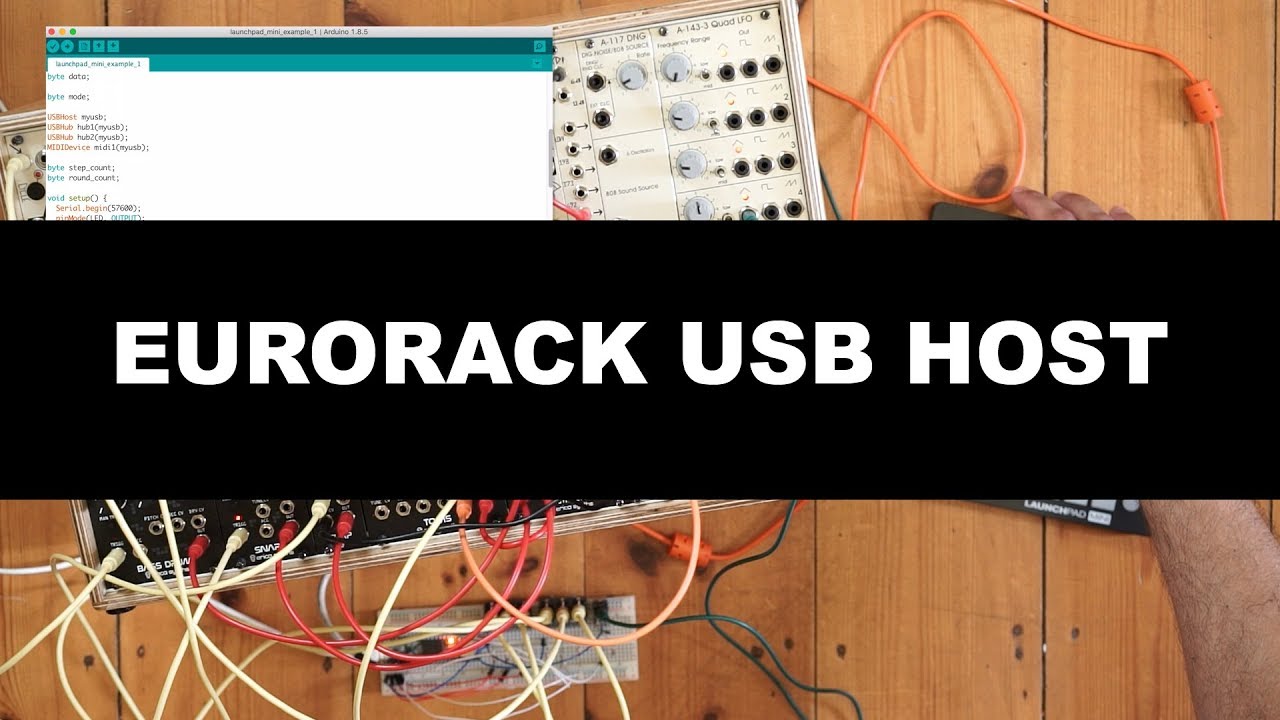
Eurorack USB Host (with Launchpad Mini as Sequencer) Code and schematic example: http://little-scale.blogspot.com/2018/12/teensy-36-as-standalone-mediator.ht...
glacial spruce
The Trellis M4 does have two analog outputs, so you could use one as a CV source.
uncut cloud
cool, but how?
glacial spruce
Plug a cable into the headphone jack (which is where the analog outputs go), and into your CV input.
uncut cloud
yes of cause, I mean the code. I will find out or ask again 😉
glacial spruce
analogWrite(A0, cv_value);
uncut cloud
@tardy jetty so, it works, DIN Midi out of Trellis M4 into RK-005. From RK-005 to Volca Modular via CV. RK-005 manipulates Midi to CV: note on/off to gate and CC 1 to CV.
So I can control the LPG or something else with the accelerometer of the Trellis M4. With the RK-005 as Midi to CV converter only one parameter.
Now I try the CV output directly from Trellis M4 via the headphone jack as suggested from @glacial spruce
tardy jetty
Very cool, thanks for checking. Yes, I've sent CV out A0 from CPX and Trinket M0 before as CV, should work for you on Trellis M4 -- just has a limited range, but otherwise great way to add features! @glacial spruce @uncut cloud
BTW, I'm very tempted by the big Retrokit RK-004 with all it's MIDI merging and clock sync capabilities!
uncut cloud
Yes, but the RK-004 is discontinued. Maybe retrokits.com are making a new version in future , I don't know.
tardy jetty
ah.
uncut cloud
@tardy jetty do you have a example code of CV out? I have to admit, I have no idea how to write the code from scratch.
tardy jetty
Sure. I have some I wrote in CircuitPython, want me to send it?
uncut cloud
That would be great.
tardy jetty
This is a pretty specific case, but try it out and see if it works for you. @uncut cloud
uncut cloud
Thanks
uncut cloud
@tardy jetty I got pitch out but not gate
tardy jetty
That example isn't doing any gate.
uncut cloud
do you have an idea what value gate is?
glacial spruce
It wouldn't be hard to add gate to that on a digital pin.
tardy jetty
Yes, @uncut cloud you can do it just like blinking an LED. https://learn.adafruit.com/circuitpython-essentials/circuitpython-digital-in-out

The next step in learning CircuitPython.
uncut cloud
Thanks, I will try this out later.
 fluid prairie
Is there any way to distinguish phonics with arduino?
Ive got an uno and a mega and im trying to assign an output when a vowel is spoken
not specific for voice recognition, i just want it to read when the speaker is louder or quieter
glacial spruce
You could do volume detection, maybe with an envelope detector. I'm less sure about vowels.
fluid prairie
all ive seen that i can do from this point is to incorporate a FFT
fluid prairie
or rather an MFCC
AFAIK i need to test the intensity of a spectrum with a no/low-noise environment to one with high noise(field)
fluid prairie
well i suspect my sound sensor module is busted
which is a shame cuz ive had it in its packaging for 3 yrs unopened
glacial spruce
It's possible it produces a different signal than you're testing for, but it's also possible a capacitor dried out or there's a bad solder joint or it was just a bad unit.
fluid prairie
it keeps giving a flat ~15 until i move the breadboard its attatched to
glacial spruce
What kind of sensor? What is it hooked to?
fluid prairie
glacial spruce
And you're getting -15 where? The main output of that module should go to an analog input pin, and those should return a number between 0 and 1023 (not -15).
fluid prairie
So i doubt im likely to break the device but does anyone have any insight on how long these mics last?
glacial spruce
I think it's an electret mic, so I'm guessing it should last many years. https://www.robotshop.com/media/files/pdf/sound-sensor-module-arduino-datasheet.pdf
fluid prairie
thx
 sage vine
Not sure if this is the right channel. I picked up a couple I2C analog joysticks and I'm wondering how I might use one with a micro-controller to act as a 2-axis/channel attenuator(inverter?) for modular synth CV signals. How do you create a voltage controlled variable resistor? How could I invert the polarity? Mostly looking for avenues of further research.
dull basalt
My Discord is updating. Brb
I'm confused about 'i2c analog' foo.
ADC means analog to digital converter and is the usual means to 'translate' from analog to digital.
DAC means digital to analog converter, and I think there are two types (voltage, and current, DAC).
I think current DACs are used to create like, small MP3 player type devices.
(the sales pitch seems to stress 'this is a current DAC' when it is available as such)
🔸 🔸
My (wild) guess is that the joystick sends a series of numbers, via i2c, to a digital device that is listening for it.
'samples' of the positions of the joystick x and y axes.
Generating the CV might employ a DAC (maybe in this case, a voltage DAC).
@graceful apex Has done some work with CircuitPython as pertains to music synthesis, I believe.
sage vine
Yeah, reading the joystick is no problem. But taking that analog signal and modifying the CV signal (+/- 5v) is beyond my ken.
dull basalt
I think some micros have built-in current DACs.
sage vine
Yeah, I don't think I can drive it directly from the MC but I could be wrong.
I'm thinking I need a separate voltage supply that I control using other components.
dull basalt
Well, when I was a kid, the Rat Shack 50:1 experimenter kit had a 'cadmium cell' which is still around, kinda-sorta. You shine a flashlight on it and it varies its resistance.
Ostensibly a PWM applied to an LED could affect it.
sage vine
Like I could maybe use a separate MOSFET for positive and negative voltages. I've got a basic grasp of most of this and I don't know how well you can control the output from the gate.
Optical resistor, yeah, there are guitar effects that use that. Seems like there'd be a more direct path.
dull basalt
I've been seeing the world through the lens of 'I bet an operational amplifier could do that' lately. ;)
Maybe there are op-amp circuits that can be driven by PWM signals.
Pretty sure an op-amp can generate arbitrary signals similar to what are needed for an analog synth's control voltage (as in an VCO input).
sage vine
An op-amp circuit sounds reasonable since it doesn't draw current (from the inputs).
dull basalt
This makes it sound like I'm not entirely offbase with the approach:
http://forum.arduino.cc/index.php?topic=180359.0
sage vine
Yeah. That at least sounds like a good place to start.
dull basalt
Looks like he used a 1 uF electrolytic to hold up the signal output from PWM to feed into the positive input of the op-amp.
Not too different from constructing a power supply, in some ways. ;)
(I'm just guessing that's a 1 uF electrolytic there)
(Scan 110.JPG)
One nice thing about PWM generation is that the micro does it in the background, and can execute its program without constantly servicing anything PWM related .. it's a peripheral that runs on its own (I think) once commanded to do so.
sage vine
Thanks. I've got a bunch of low-noise op-amps I picked up to try and replicate this: https://bastl-instruments.com/instruments/dude
Portable 5-channel Monophonic Audio Mixer That Can Drive Your Headphones
Just need to start trying stuff.
Hook up the output to the multimeter...
dull basalt
It actually looks like a lot of fun. I like his article (The last one I cited).
Just so you know, @unkempt linden wrote some articles; I haven't spent time enough with them to know just what nuggets they contain.
I didn't see any op-amp circuits in his collection on learn.adafruit.com (I thought that was planned or already done; can't find evidence of that, at a glance, however)
This one looks promising as well:
https://controls.ame.nd.edu/microcontroller/main/node40.html
Even an entirely analog multimeter won't give too much insight into what happens dynamically; oscilloscope always suggests itself at this point. ;)
Digital multimeters are either very limited in that respect, or (perhaps) cost good money to get the advanced features needed.
Yeah that last link is a bit rich in the formulae. Pedantic, not all that HOWTO oriented.
sage vine
Indeed. I'm looking for a deal on an o-scope. I'm a software guy, hardware is for-fun right now.
dull basalt
Just tell me where to aim my solder gun
I got a nice decent oscope at a hamfest this time last year for 80 bux. Maybe 2 yrs ago.
sage vine
But a meter should tell me if I'm getting a consistent CV.
dull basalt
If you knew in advance that nothing was going to get damaged, a voltage controlled oscillator would probably confirm what you wanted to know, better, as your ears would pick up a warble at human warbling speeds. ;)
If it's warbling fast enough that you can't hear it you probably don't care about that too much (unless its warbling with a lot of amplitude change haha)
I generally try to bring it back to the human domain with sights and sounds, to see what my senses can pickup, if I don't have proper test equipment on-hand.
sage vine
VC != VCO. VC is steady, just control. There's actually a "hamfest" here on Sunday. Might have to check it out.
dull basalt
I'm trying to remember what scope I picked up.
http://amzn.com/B007T6XNCA Owon PDS5022T
 unkempt linden
@dull basalt cds cell (cadnium sulfide) aka photoresistor.
sage vine
Hamfest is 8am to noon. What happened to sleeping in and working all night.
dull basalt
Yeah if you get there early there can be some advantage. Some stuff gets sold by around 8:05 a.m. ;)
(maybe earlier!)
sage vine
Hacky but it worked: https://www.youtube.com/watch?v=VYs4dSEKCUg
 unkempt linden
Probably a lowpass filter on the pwm signal would work,
You want to average it to get the control voltage.
An actual DAC would be better as it would just give you a voltage.
sage vine
I get 0-1024. I need an output of -5/5 volts.
unkempt linden
You'd probably have to amplify it and/or shift it if you needed something +/-
sage vine
Yep
dull basalt
I smell a show and tell
sage vine
Thanks @dull basalt
The mod input on a synth is just a 0-5v signal. Any resistor will work.
dull basalt
That's a lot from a little! I really like this.
sage vine
It sends 5v out and takes back a signal.
dull basalt
I usually begin these discussions with the idea 'this isn't going to help, I hope it doesn't just annoy them'.
sage vine
The mod input on a digital synth isn't quite the same as modular CV.
dull basalt
If you put a 3" wire 'antenna' on the input of one of six hex inverters, depending on variables I don't know about, you can (sometimes) get a theramin-like effect. Bascially floating the input where the antenna is hooked up to.
I've forgotten the part number; probably DIP 14 packaged.
SN7404 maybe
I noticed this accidentally one day; it was fairly deterministic.
sage vine
I smell a show and tell 😃
unkempt linden
'04 is a hex inverter, yes
The effect would probably depend on which logic family (plain TTL, LS, ALS, etc)
dull basalt
SN74HC04N is what I have on hand (and very likely to be the exact part number I was using)
sage vine
But yeah, an op-amp(s) circuit is probably the way to go to convert the low current/voltage MC output to something the synth can understand and possibly invert it. Now I just need to figure that out.
Could use one op-amp as a switch. If the value is below 512 use the negative circuit and otherwise use positive.
dull basalt
I'll leave it at that .. late for dinner (and other night time stuff).;
sage vine
'night
dull basalt
that was fun. enjoyed the heck out of your demo!
 proven arch
Can anyone help me understand why I get
RuntimeError: Unable to allocate buffers for signed conversion
glacial spruce
Sounds like your code ran out memory?
echo hedge
@proven arch More info would be helpful. What code are you trying to run? What sort of output?
opaque cloud
Woot! Got the dual SIDs going! https://www.instagram.com/p/BvKEbPMFOF7/

Instagram
8 Likes, 0 Comments - William (@theshaggyfreak) on Instagram: “Here’s a test of the SID2SID upgrade! It’ll be fun to write some music with 6 channels. #c64…”
junior prairie
that sounds fun
opaque cloud
Someone who’s more of a programmer could probably get some serial communication going.
mental ruin
@opaque cloud That's sweet! I have a pair of SIDs waiting to be turned into a synth and I'm eyeballing a FPGASID for a related project
opaque cloud
Awesome! I love using the original hardware because it's what I grew up with. I use the MSSIAH cartridge as a front end for doing SID stuff on the C64. I think I'd like to do a stand alone Eurorack module at some point, though.
mental ruin
@opaque cloud http://busycircuits.com/alm012/
you could probably also adapt the midibox sid modules with a bit of work
opaque cloud
indeed
 shell nymph
simple (I hope) audio question: I'm getting one these boards https://www.adafruit.com/product/2217 However the only speakers I'm seeing that match close are these https://www.adafruit.com/product/1669 . Will they work? Or should I look around for 2w speakers?

Would you like to add audio/sound effects to your next project, without an Arduino+Shield? Or maybe you don't even know how to use microcontrollers, you just want to make a sound play ...

Listen up! This set of two 2.8" x 1.2" speakers are the perfect addition to any audio project where you need 4 ohm impedance and 3W or less of power. We particularly like these ...
dull basalt
@shell nymph
The product description for those speakers specifically mention 'TS2012' which (apparently) is equivalent to the amp shown for
http://adafru.it/1552
.. I believe this is the same audio amp chip as in the schematic for the FX board you're considering.
The amp's description is more specific about 'efficiency' and what that gives you (portable, battery-operated power works better for your needs if the project is 'efficient').
The schematic suggests efficiency goes up as the ohms goes up (anything above 4 ohms is better than 4 ohms, for efficiency's sake).
However, one of the texts suggests 4 ohm speakers will sound the loudest.
So if you have to have it louder, you sacrifice efficiency ('run time') for battery op.
shell nymph
Awesome. I'll get those speakers then. Thank you :)
dull basalt
hehe hey no problem.
tall mango
I just tried hooking up two adafruit audio boards
(Specifically these ones:)
https://www.adafruit.com/product/2220
https://www.adafruit.com/product/2342
And both won’t trigger audio. I quadruple checked the pinout of both and the audio won’t trigger no matter what I do, I’ve used a tactile switch, vibration sensor, even just shorting two wires. Does anyone know what I’m doing wrong?

Would you like to add audio/sound effects to your next project, without an Arduino+Shield? Or maybe you don't even know how to use microcontrollers, you just want to make a sound play ...

Would you like to add audio/sound effects to your next project, without an Arduino+Shield? Or maybe you don't even know how to use microcontrollers, you just want to make a sound play ...
glacial spruce
You have SD cards in the proper format installed with appropriate sound files? You're grounding the trigger pins?
vapid merlin
Hi, got a couple of MAX98357A breakout boards, i'm playing 5 seconds of audio chucks in a loop (25 seconds between them), the problem i have is the third time i play the audio it sounds saturated, i noticed an increment on the power consumption of the amplifiers.
So i removed R1 from the breakout board to be able to use the SHUTDOWN signal, so i can turn off the amplifiers when not using them. But this doesn't solved the problem, i can record a tiny video to show yall the problem.
Also, SCK and WS clocks are not running when i'm not sending data, i don't know if that's all right tho.
vapid merlin
Got some help from Maxim integrated, the saturation can be because of the SCK clock running while there's no WS clock, so to avoid this I need to disable the amp via the SHUTDOWN and then remove both SCK and WS clocks or send 0's to the amp while I don't need sound output. I will test it tomorrow and let you know if it solves the issue.
glacial spruce
That's a strange one, yeah I'm curious how this will work too.
vapid merlin
Hi, just a little update, I got both I2S clocks running while sending zeroes but I can't get the audio playing well in the second loop iteration, it does sounds fine on the odd loops, sounds bad on the even loops, so I guess it's more a software problem than a hardware one, I will try with a feather board I just got and see how it goes
glacial spruce
Interesting. Sounds like a low-level issue of some sort, don't know if it'll turn out to be timing, a race condition, startup after pausing, or what. So many variables.
vapid merlin
Agree, but is the first time I work with audio and mp3 decoding so I'm almost sure I'm doing something wrong, a lot to be learned
 livid shell
@here Hello fellow makers 😃 Would this be the right place to debug a difficult issue I am having with the Music Maker Featherwing? It crashes after playing half a second of audio and the whole microcontroller restarts.
I can post the backtrace here, but be warned...it's just instruction addresses
I've tried with 2 different SD cards and 2 different MP3 files...always same issue
livid shell
It works if I don't use interrupts
But...I need to use interrupts I think, otherwise my project wouldn't make much sense.
I am trying to play music based on occupancy (Adafruit PIR sensor), and switch off the music when the room is unoccupied, i.e. when the PIR sensor returns 0
glacial spruce
Could be the interrupt routine is interfering with transferring the audio stream. Don't really need to use interrupts, since internally it's running a loop to transfer the data a chunk at a time: you can just check the PIR sensor between chunks.
livid shell
@glacial spruce Oh! So I am going to try doing a PIR check every X milliseconds in the main loop()
livid shell
Hmm so when you said "check the PIR sensor between chunks", I guess I have to find a way to synchronize with the audio data transfer loop instead of just checking at X time intervals in the Arduino main loop
Because right now...it just plays half a second or so of audio, like before
glacial spruce
Weird. So it works if you don't stop, but only runs for half a second if you check the PIR?
livid shell
@glacial spruce Yes! The only two scenarios I can produce (so far) are:
- Run for a fraction of a second and stop, in the case where I use "startPlayingFile" function to play the music.
- Play the entire song (few minutes) and then go back to reading the PIR, in the case where I use the "playFullFile" function.
I am currently overriding the class method definition of "playFullFile" so that it checks the PIR in between feedBuffer()s. It's a dirty hack but let's see if it works
glacial spruce
Yeah, that's what I was trying to describe when I said "check the sensor between chunks".
livid shell
@glacial spruce It worked!!!!!!!!!!!!!!!!!!!!!!!!!!!!!!!!!
I have been taking pictures and videos of the whole process. When I do my write-ups on Hackaday, Hackster, Make, Instructables, etc I will give a big hearty thanks to you 😃
echo hedge
hey, what cable would folks recommend for me making my own din to 1/8" midi cables?
glacial spruce
You'll want a shielded twisted pair cable, probably something pretty flexible.
tardy jetty
@echo hedge if you don't want to use commercially made ones another option is to cut a DIN-5 MIDI cable in half and wire it into one of these https://www.adafruit.com/product/1800 or these https://www.adafruit.com/product/2790

Repair or design your very own audio cables with these nice and durable phono-jack connectors. This is a great plug to make your own cable with. it's made out of durable metal with a ...

One truth about working with audio is you always need the cable or adapter you don't have in your toolbox. That's why we love these terminal-block audio connectors so much. No ...
echo hedge
@tardy jetty I was hoping for some I could buy off digikey with my next order along with connectors
tardy jetty
you mean a full cable and all, or the male DIN-5 end? other?
echo hedge
just got an oshpark email telling me my next rev of pygb are back so I'll need to make the order soon
tardy jetty
excellent!
echo hedge
@tardy jetty just the wire. I have the ends in my cart already
echo hedge
three conductor or two plus shield?
tardy jetty
I think three conductor would make it easier to work with, but there are others here who know more. @fickle leaf @weary gyro thoughts?
fickle leaf
For short distances ( < 2m) "classic" MIDI doesn't require a shield. However, as @tardy jetty discovered, some vendors don't pay attention to the standard, so a two-conductor shielded cable is probably best. Connect the two conductors to the Tip and Ring with the braid to the Shield.
A USB cable would be overkill, but a stereo earphone cable should work.
echo hedge
@fickle leaf any recommendations?
fickle leaf
@echo hedge ~~I've successfully used these. Nice and flexible. All the ones I've used so far have been shielded. https://www.amazon.com/dp/B00NO73MUQ/ref=twister_B00P28VN38?_encoding=UTF8&psc=1~~
@echo hedge Cancel that. Just checked the latest shipment -- they are sending ones without braided shields now. Bummer.
glacial spruce
55A1822-22-9/96-9CS2275-05-ND should do the job, but might be overkill
fickle leaf
The quality of the spiral-wrapped shields on these aren't as nice as ^ but should be okay for MIDI. https://www.digikey.com/products/en/cable-assemblies/barrel-audio-cables/463?k=&pkeyword=&sv=0&pv493=279&pv493=56&sf=0&FV=b58000c%2Cb5c0008%2Cb600016%2Cb600003%2Cb600009%2C1f140000%2Cffe001cf&quantity=&ColumnSort=1000011&page=1&stock=1&pageSize=25
Cable Assemblies – Barrel - Audio Cables are in stock at DigiKey. Order Now! Cable Assemblies ship same day
glacial spruce
A141502-05-ND is also a reasonable choice.
fickle leaf
I prefer to do that if possible. Tough to find the really flexible cables when searching through DigiKey's bulk cable catalog.
glacial spruce
Truth. I tend to buy up really flexible cable when it shows up on the surplus market and hang on to it until I need to make up a custom cable. I'll also harvest cables off electronics I'm discarding.
mental ruin
silicone-carne cables are ❤
tardy jetty
I came into a substantial wad of MIDI cables when Perfect Circuit Audio was clearing out some old stuff and man, the KORG cables are so nice and flexible.
mental ruin
anyone have recomendations for not arm and a leg expensive USB dac+ headphone amp combos? As much as I would love to make my own, I would also like to have something that works some time this year
don't need audiophile tomfoolery, just something that works well
glacial spruce
M-Audio and Griffin used to make some nice ones (I have and use them), but I don't know the current offerings.
 dusty scaffold
@tardy jetty Nice!
junior prairie
@mental ruin I've heard good things about the objective 2 amp and ODAC
depends on your definition of arm and leg
mental ruin
Those are within reason, though I would prefer something integrated
junior prairie
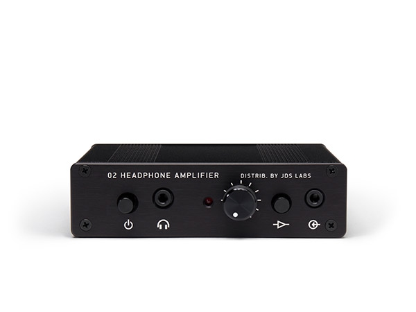
JDS Labs
Objective2+ODAC is an Objective2 headphone amp with integrated ObjectiveDAC. This high performance amp+DAC combo ships fully assembled, tested, and ready to use. Includes USB cable.
there's a combo version
mental ruin
well well well
junior prairie
I tried to build an objective 2 myself, even redesigning the pcb, but I failed
I wanted rca inputs and the published pcb didn't have them
mental ruin
awwwwe yisssss:
https://www.massdrop.com/buy/massdrop-o2-sdac-dac-amp

Massdrop
Free Shipping in USA | Massdrop exclusive product, price and reviews: Massdrop O2 + SDAC DAC/Amp | 2.2K+ Sold | Ends 4/30/2019 | For the objectivist...
junior prairie
it was way too ambitious of a project for when I did it
I'm not familiar with the SDAC
mental ruin
nor am I, but that price is pretty attractive
junior prairie
true
mental ruin

Headphone Reviews and Discussion - Head-Fi.org
[ATTACH]
In "traditional" high-end circles, it's not uncommon for amps, preamps, or other components in the $1k-2k range to be considered "budget"...
junior prairie
let me try and remember what dac I was looking at recently
cheap as chips https://www.ebay.com/itm/ES9038-Q2M-DAC-DSD-Decoder-Support-IIS-DSD-384KHz-Coaxial-Fiber-DOP-/272844357070?afsrc=1&rmvSB=true

eBay
ES9038Q2M perfect than the previous generation ES9028Q2M, thicker sound, direct support for coaxial optical DOP. Coaxial: PCM44.1K-192K 24BIT / DOP DSD64. Fiber: PCM44.1K-192K 24BIT / DOP DSD64. IIS / DSD: PCM44.1K-384K 32BIT / DSD64, DSD128, DSD256.
and higher specs I think
Hi, this is my first post in this forum. I have a short question: Do any of you have any experience with this ES9038Q2M board? ES9038 Q2M DAC DSD Deco
It seems even the soundcard built into my motherboard can do 24/192 these days
not that it really matters to the ear but 24/96 feels on the low end
While I'm here, anyone wanna give me a 2nd opinion on this? http://phonoclone.com/diy-pho5.html
fickle leaf
@mental ruin I started using a PreSonus Studio 2|6 USB interface ($150 - $180) a few months ago. In addition to the regular audio ins and outs, it has "classic" MIDI. Very pleased. https://www.presonus.com/products/Studio-26

PreSonus
Also using their StudioOne 4 Pro DAW but started with their free DAW to see if it was any good. Quality stuff.
 opal hinge
i don't know if it's the right place to ask, but i have a midi song with a frequency for each note, but the thing is that i use a converter that use this midi (and the frequencies with it) but for some songs, they are way too high, so, is there is a way to lower the frequency of a midi file (i don't even know if it's possible)
If someone have a idea just @noble silo
dull basalt
There might be a 'transpose' function in the MIDI 'language' to change the key.
opal hinge
And how exactly do i do that ? With Audacity ?
dull basalt
MIDI is a series of messages written in ASCII (1's and 0's) that you could (in principle) examine in a text terminal (like a 'shell' in Unix or the 'C:>' prompt in MS-DOS/Windows).
Audacity deals in waveforms stored digitally in some fashion.
The two domains are very different.
opal hinge
oh i kinda get it
so there is a function if i enter it in a text terminal to change the key ?
dull basalt
It looks like MIDI doesn't always use RS-232 as the transport layers and that it's more appropriate to think of the MIDI message stream as a series of bytes.
(Which may not always be in the printable ASCII range)
I'm just assuming changing the key would be provided for; I don't know offhand.
It would seem odd to me if actual (mathematical) note frequencies were specified. MIDI is a language.
opal hinge
one small question, does UP/DOWN octave function work the same way ?
dull basalt
That sounds like a transposition of exactly one octave.
Which is a subset of a key change I'd think (some key changes are not simple octave shifts).
opal hinge
the midi file work fine, but if i try to convert it into tones (for Arduino) the frequencies go from e+15 to e+20
dull basalt
An octave is an exact (mathematical) doubling of frequency, iirc.
How are you converting it? Ultimately the Arduino would deal in Hz (cycles per second).
opal hinge
i use a website (https://sshdl-6.extramaster.net/tools/midiToArduino)
it work fine for 50% of my files
but the other half keep have way too high frequencies
same goes for the delays
opal hinge
okay, so maybe that totally unrelated to the midi file (maybe it's due to the conversion mecanism or something) but the thing is that when i take a midi that work fine and a midi that doesn't work and compare data, they doesn't look that different (in Audacity at least), but maybe there is a program to know in advance a estimation of what the frequency will be
dull basalt
I guess you could write one that evaluates the expressions to look for exponents above a certain number. If those are exponents, that is. ;)
opal hinge
okay and one last question, do you know a bit about audacity (or any other programs that can reduce pitch of a midi file) ?
because i think i'm not doing it the right way
dull basalt
Sorry, if Audacity works within MIDI I didn't know about that until just now!
(that's pretty cool if it's doing so)
opal hinge
well it doesn't seem to work that well with it
it's mainly to convert it to WAV i think
well maybe do you know a program that is able to work with midi ?
Doesn't FL studios can do that ?
dull basalt
Linux has some kind of software that similates MIDI hardware; and there's outright MIDI hardware.
But I think the MIDI source file and/or how it got translated into tones is the issue.
Sounds a bit like the translator is wrong, as you've already suggested the MIDI files are fine.
opal hinge
the odd thing is also that i tried using 2 other converter which both of them didn't worked with this file
dull basalt
Well I mean the standard method I've used in the past was to translate twice. Once to some other format, and then a second time back to the original format.
That tends to imbue the final product with the bias of the translation program. ;)
opal hinge
i never tried that, i'll see the result thank for the idea
but the problem is that i don't see any programs to convert tone to MIDI files
dull basalt
I'm not clear on why you think various programs 'should' already exist. ;)
I usually find that they don't exist, or that I cannot locate one that does what I want it to do.
It's a big territory to cover.
opal hinge
well i'm going to try to create the program myself tomorrow, thank you for the help 😃
opal hinge
okay i managed to understand some of the problems and now it fully work but now i have another questions for MIDI users, do you guys know a way to merge tracks of a midi clips ? (I tried with FL studios but i couldn't find how)
sage vine
What do you mean by tracks? MIDI supports 16 channels. Do you want to merge the data stream from 2 channels or the rendered audio?
I've never heard of bouncing down MIDI channels...
vapid merlin
Hi all, I'm still working on my mp3 decoder project, I have a good progress, still some bugs to be solved but I need to listen the generated audio to know if I'm making progress, do you know any debug technique that does require me to hear the generated audio?
That doesn't require*
glacial spruce
It's tricky, as you have to perform a frequency analysis of the generated audio to determine whether it contains the desired information (ISO 11172 defines what constitutes a valid decoder, and says "the decoder shall provide an output such that the rms level of the difference signal between the output of the decoder under test and the supplied reference output is less than 2−15⁄√12 for the supplied sine sweep (20Hz–10kHz) with an amplitude of −20dB relative to full scale. In addition, the difference signal shall have a maximum absolute value of at most 2−14 relative to full-scale."
You can find some test files here ftp://ftp.tnt.uni-hannover.de/pub/MPEG/audio/mpeg1/compliance/
vapid merlin
Thanks for the information @glacial spruce , I will check it
 broken parrot
hi there !
currently having fun with sending dtmf stuff from a laptop to an Arduino + a mike, I'm having troubles directly connecting to the aux jack of the laptop with minimal circuitry in between ( that is, a single cap on the R channel and connecting to Gnd the middle pin ), anyone with an idea ? ( the circuit works fine with the mike's output directly connected to A0, but I can't figure out a working wiring :/ .. )
nb: the laptop is an old macbookpro ( 2011 ), with which I never had success when trying to us this: https://www.espruino.com/Headphone
thanks 😃
glacial spruce
Hmm, you might have two problems. One is that the aux jack on Macbooks is often a 4-conductor jack with a microphone lead included. You can find a splitter cable that breaks it out into two standard 1/8" jacks (microphone and output): I do this to use an ordinary gaming headset with both my Macbook and my phone (which uses the same 4-conductor jack).
The other problem is that there might be a level and/or impedance mismatch, and you might need nothing at all, a capacitor, a resistor, two resistors, three resistors, or a combination of them.
broken parrot
@glacial spruce hello :)
- for the 4-conductor jack thing, I 'll go get 2 of those & cut them open to get easier wiring for tests
- the 2nd thing you mentionned may actually be why I can't make it work
I currently tried with a voltage divider & a cap, but it didn't work correctly ( getting garbage out )
( no digging some howto's .. )
-> thanks for the hints
glacial spruce
It occurs to me that an Arduino can't digitize very fast either, I don't know if it's even capable of decoding DTMF (but there are chips available that do so for you).
broken parrot
@glacial spruce for the dtmf decoding part, I'm already set ;p ( at least, when using a mike ): using "Goertzel.h" for now ( I'll have to test Paul S. implm of "AVR_DTMF", but I'm not sure I'll get it to compile without errors, so I ended up studying it - there's assembly there ! ^^ - and planned to try modding the one I'm using to benefit from some "Free Running Mode" analog reads ( .. )
-> I just stumbled upon an "enveloppe follower" circuit( but it's not what I'm looking after .. am I ? ), but I think I'm gonna try diggin iphone <-> arduino stuff ( some use FSK, but I bet I can borrow the connections used and maybe get something out of that ;p )
silly, but it works fine when receiving stuff from laptop ^^
the WebAudioApi part ( to crudely "encode" stuff )
( if the above could be useful to anyone ;p )
ps: this is close to the code I intend to use to talk to my mailbox across the intercom line + air gap ;P
😄 ( -> don't know yet if it will work .. and if I can manage to get non-audible sounds over that air gap .. 😉 )
glacial spruce
I don't think an envelope follower is what you want.
broken parrot
yup, me neither 😉
from what I can read in other places, a voltage divider is always present, and the value of the AC coupling cap vary from one schematic to another
also, some add a cap to Gnd ( ex: 47pF for the one I'm digging right now .. )
since I did all my current tests with a TRS cable, I guess I'll have to find a TRRS one & try with it instead & hope for the best
glacial spruce
47pf is really small for audio frequencies, I doubt it would have much effect.
broken parrot
also, the max output voltage on the mcbpro is said to be 2VRMS & the output impedance < 24 Ohms
glacial spruce
It might be worth just writing a simple sketch that reads the analog input and prints back what it gets. If you get a bunch of small numbers, your level is too low. If you only get small numbers and large numbers and not much in-between, your level is too high.
The problem with adding a capacitor is that it removes the DC level, so it'll get pulled (on the Arduino side) to near ground, then when the AC signal shows up, it will go both positive and negative (and the Arduino does not like negative voltages).
broken parrot
sure, and the goal being getting 512 😉
glacial spruce
You might do better without the capacitor, so the DC level is preserved, but the Mac may produce negative voltages as well.
What you may need is a capacitor and a voltage divider to set the quiescent bias to about 1/2 your Arduino supply voltage.
broken parrot
not sure about C3, but R2 & R1 are as I did before ( to get 2.5V ), and C1 is below what I had
glacial spruce
I doubt C3 is important, and yes R1 and R2 are the sort of "pull middle" arrangement I had in mind.
The value of C1, along with the parallel impedance of R1, R2, and the Arduino input port form a parasitic high-pass filter, but the corner frequency should be low enough to work with a range of values of C1.
So with no signal input, you should get values around 512 like you said.
broken parrot
-> I previously had a 1uF cap
glacial spruce
1µF is pretty big, but should still work (if it's an electrolytic capacitor, you may get some leakage issues).
broken parrot
since it was an electrolytic, I put it with the + on the arduino side ( since it has the highest voltage )
glacial spruce
I do notice that in the diagram, they're connecting FSKIN to D6 instead of an analog pin, which seems like an odd choice.
broken parrot
yup, don't know for sure for using D6, but maybe part of their FSK thing ( I won't have fun with FSK for now, dtmf is a good start, and before that, getting some levels debugging ..
)
glacial spruce
Looking more closely at the code, I see what they're doing, and possibly what the disconnect is (which is also why I was confused about the Arduino being able to decode at that speed).
broken parrot
this may be of interest to you ;)
https://www.slideshare.net/ShipengXu/data-transmission-through-audio-jack-on-ios


 glacial spruce
So are you routing your data to an analog pin or a digital pin?
broken parrot
to an analog one
int sensorPin = A0;
( .. )
// This reads N samples from sensorpin (must be an analog input)
  // and stores them in an array within the library. Use while(1)
  // to determine the actual sampling frequency as described in the
  // comment at the top of this file
  /* while(1) */
dtmf.sample(sensorPin);
nb: iyo, would I be able to see voltage changes going up to 5V on a connected multimeter ?
( or would these be too fast to grasp ? .. )
sterile parcel
This might sound quite weird but oh well
About a year ago I made an audio amp with lm386. It works great to this day, but back then I didn't really know much about electronics. I'd consider its construction quite weird, because it uses transformers to separate input from the amp. When I was testing it back then I wasnt satisfied enough with capacitors. The amp produces (in my opinion) pretty high quality, highly detailed sound. ( when playing back music You can literally hear where instruments are playing ) Anyway, recently it got me thinking, why is that? Designing it took me 6 months and was pretty much trial and error, so I was curious what do You think? I can post pictures and schematic if anyone will be interested.
broken parrot
hi there @sterile parcel pretty interesting, ' would love to get more infos on your work 😃
sterile parcel
Ok, I'll get You some pictures
broken parrot
nb: don't rush yourself into it: I'll be busy messing with wires for the few hours coming ;p
broken parrot
:)
-> that' very kind of yours
sterile parcel
Yes, rca jacks are taped xP
broken parrot
haha - I was looking at those precisely ;p
sterile parcel
The board is pretty bad quality and when I soldered them they were just taking pads off so I decided to just tape them
My two later amps made with ne5534 are built on higher quality boards and jacks are soldered, but this was my first creation so I didn't know how to pick good boards either
glacial spruce
You'll see a lot of transformer coupling in high-end audio. I wonder how that would sound with a class D amplifier.
sterile parcel
@broken parrot
broken parrot
thanks ;)
-> I'll have a deeper look at it after few mins 😉
sterile parcel
Ok :)
interestingly enough, this amp is quite resistant to interference - i power it with 6v switched mode power supply and it does not buzz even if I touch input plug with my hand. it works where my ne5534 amp has failed. I made ne5534 one to replace this one only to find out that it does not like my audio source and it was humming like crazy. LM386 one on the other hand delivers clear sound no matter what
I mean ok, when I crank the volume to maximum it starts clipping
but I guess nothing is perfect
and please ping me when You reply to make sure I see Your message
ornate meteor
@sterile parcel there are a few of my rambling thoughts on your circuit
yeah clipping is just a property of how amps work, since they cant provide higher output than the source power voltage. if you tune up the output so that 0.5v in is 6v out, then 0.6v in would need over 6v out to be shaped properly. a 6v supply cant do that so it stops rising.
The circuit itself looks pretty straight forward, you have basically nothing that can significantly modify the sound outside of the transformer and amp itself. You also have no capacitors on the transformer side so you arnt accidentally building a filter. as long as your circuit paths themselves are not creating capacitance the signal should stay pretty clean.
The transformer input is interesting, i guess its there to change the impedance that the source and amp sees, which likely adjusts both of those so that the device sees something more stable. For example, make the source see high impedance, and the amp input see low impedance,
and/or it changes the output voltage range to something easier to amplify. eg from 0.5vpp to 2vpp. using a good transformer to raise that up lets the amp spend more of its effort providing the current your next stage needs and it might let the amp have more of the signal in its 'optimal' input range. eg maybe its less accurate for signals under 0.5v so raising it up means more of the signal is linearly amplified.
And maybe it can also isolate the input DC levels, since you dont have negative voltage and your input might, you need to be able to adjust the 'center' of the signal to be someplace the amp can see its full range: between its own references of ground/6v. There are other ways to do that though and the LM386 might be doing that on its own.
It also protects the amp from shorts in the source, the transformer itself could fail from DC issues, but they shouldnt hurt the rest of the amp.
sterile parcel
Transformers are there to separate input device and the amp. Back then when I was making it, I didn't even know that there is something like input impedance, I didn't really know how all this worked, it was all trial and error. I was just playing music and randomly adding parts to the circuit to see what it does.
I'm not sure if You noticed that the output ground is connected to transformers primary side rather than secondary. I'm not sure why I did that though and how it affects the quality
glacial spruce
Since your amplifier ground is connected to the input ground and the transformers' primaries, it's a common ground, so the transformers won't provide isolation. Many transformer-coupled circuits have separate grounds for the input (and primary) and the output (and secondary) to achieve complete isolation, which can be helpful with ground loops, hum pickup, and floating voltage issues.
sterile parcel
Ok, but I remember I had to put a cap across primary and secondary gnd to make it work
Putting these transformers into the circuit fixed all quality issues
glacial spruce
Whoops, you're right, I missed that capacitor separating the grounds. It might make more sense to ground the output jack to the secondary (and amplifier) ground, but if it works the way it is, it's easier to leave it.
sterile parcel
Yeah, now when I look at it I can't help wondering why did I do it that way
glacial spruce
I've had that same feeling when looking at some of my old circuits. I just found one I built years ago, and the construction makes me wince.
junior prairie
No help needed, but I bought these clear headphone jacks for my cmoys from lcsc and they were too cool not to share.
Buy Korean Hroparts Elec PJ-3240-5A only $0.2084 at EasyEDA components online store LCSC. Connectors|Audio & Video Connectors datasheet, inventory and pricing.
sj1-3523 footprint
glacial spruce
I've seen those in some gear, I like 'em.
sterile parcel
What does this do?
junior prairie
@sterile parcel it's a headphone amp
sterile parcel
Oh, that's really cool!
Can I have the schematic?
 sly patrol
I want to connect a Neotrellis to an FX sound board. Basically connect multiple amps to the same speaker, so I can overlay music too large for the controller with sound effects from the controller.
Can anyone offer me guidance on how to do this?
tardy jetty
You'll want to probably use a mixer for this. I believe @glacial spruce shared some mixer schematics on this channel.
sterile parcel
@junior prairie Thanks!
light crag
hi i got a kenwood ka35 i have a problem the sound sounds awfull like a radio on wrong frequency
i would like som help
https://cdn.discordapp.com/attachments/396473529505415169/579345947302166529/IMG_20190518_183336.jpg this is the inside


not much inside
glacial spruce
Hmm, my first guess is that the electrolytic capacitors are old and it's oscillating instead of amplifying.
 neat summit
The photo is a bit blurry to tell for sure, but recapping that beast with new ultra-low ESR caps can't hurt & would only be a $20 repair.
light crag
So i need replace all caps oh gosh
No capasitor looks bad what i can see
this is how it sounds if this helps
i tooks nightcore song btw
junior prairie
kinda sounds overamplified
light crag
Ok
glacial spruce
Yeah, that sounds like ordinary clipping. Try attenuating the level of the input signal.
dense kettle
Hi folks, I have an AT problem that begs for your Audio genius 😃
We have a speech device user who has an iPad (with a TRRS Jack) and wants to send the output of that to the input of an iPhone.
So, I daisy chained together a lightning->TRRS , a mic/headphone splitter, a TRS Aux Cord, another Mic/headphone splitter and hooked them together
So audio should go from the headphone jack on the iPad through the splitter out the headphone port through the aux cord into the mic port and into the lightning adapter.
It totally doesn't work.
I'm thinking both sides need to "see" a valid headset before they'll play? Anyone have a better solution for this? Anyone know of a device (rPi zero?) that can pipe audio into a phone via bluetooth?
Anyway, let me know what you find.
 novel elk
@dense kettle The immediate thing that comes to my mind is the aux cord. If it's unmodified, it'll simply be connecting mic to mic, speaker to speaker, on the adapters. It'd have to have the wires swapped somewhere in the middle so it's connecting to the correct places.
dense kettle
I'm using a TRS aux cord, so it should be ok, right?
novel elk
Don't think so. I think the aux plugs on radios and stuff are wired differently, for input
dense kettle
output of the ipad goes through splitter so mic is on one (ignored) and stereo is out
novel elk
Aux cords are reversible, so I don't think they do any shenanigans.
dense kettle
Hmmm... I can make a custom aux cord if I knew which pins to map to what
I think part of this is that the iPad & iPhone treat the cords differently if they detect that there's a mic
and the daisy chain might screw with that detection
novel elk
I don't think they do, since TRRS stuff is analog
Aha, sweet. Adafruit's stuff is even better than I thought it was.

One truth about working with audio is you always need the cable or adapter you don't have in your toolbox. That's why we love these terminal-block audio connectors so much. No ...
So, that has left/right and ground labeled, with the 4th being, presumably, for the mic.
So, getting two of those. The one on the tablet end would have the L and R going out, nothing on the Mic, and the ground. The one on the phone end would have both the L/R connected on the mic slot, and the ground.
I am nowhere near certain that this would work, it's just going off of speculation on how I understand them.
Which... could be flawed.
dense kettle
Yeah, I have a TRRS Aux cord local, I can cut it and wire accordingly
I'm not confident that will solve it, but it's worth the shot
I'll be in the workshop tonight
novel elk
Hope it works, but as I said I'm not totally convinced.
dense kettle
Yeah, I'm thinking I might need a mixer in the middle or something. we'll see - thanks
fickle leaf
@dense kettle I don't have experience with TRRS, but recall that the wiring didn't seem obvious/traditional. Here's how the NeoTrellis did it.
Shield for the mic input threw me off...
dense kettle
Ugh
you kidding?
Ok, but these adapter should know that
They should map those to standard mic & headphones
right?
Let me get a TRRS cord and multimeter
fickle leaf
One would think so...
dense kettle
Yes, they do - they split into Sleeve = GND on both jacks
on the headphones they put tip on tip and outer ring on ring
on the mic, they put sleeve -> tip
It's weird but the short answer is we should be good
fickle leaf
Excellent.
dense kettle
it still doesn't work though
fickle leaf
Does the adapter work when connected to just headphones?
dense kettle
So... that's actually hard to test
because I only have TRRS headphones
It acts like the iPhone doesn't have a headset plugged in at all
fickle leaf
(I have devices that detect the load of the headphones, not just plug insertion)
dense kettle
Yes, that's what I think I'm seeing
And since both sides require it
you're kinda screwed
Both sides want to be plugged in last
An analog isolator would probably solve it
Or a mixer
fickle leaf
TRRS headphones should present the proper load when connected to TRS, though.
dense kettle
Yes, they work as headphones
no mic/volume control
😕
This shouldn't be this difficult
fickle leaf
Surprised that the iPad can't connect with the phone via bluetooth, but I don't have a setup like that to test.
dense kettle
The iPad can't expose a headset profile over bluetooth
It really seems like this should be doable
Maybe I'll ping @tardy jetty and @coral geyser and see if they have ideas... 😕
tardy jetty
@dense kettle I don't know of a solution, but one place to look is at AudioUnit plugins, which are often used for inter-app operability, some of which use Bluetooth. So maybe there's an iOS app to run on the iPhone that can use an AU plugin to get the iPad audio as an input via BT.
dense kettle
Good thought. I’d really like a simple “oh just ode this isolator” or “oh you just need a load so add a resistor 😃
tardy jetty
🖐
 stray narwhal
I had to use instrumentation-quality accelerometers regularly 20+ years ago. Should still know the fundamentals.
 amber grove
Where do i begin 😅 hardware adafruit sound fx , uno, mpu6050
Mpu 6050 limited just to a single axis and acts as a switch for the fx , Can you help ?
stray narwhal
So https://www.adafruit.com/product/2133 and some kind of Uno and something like a https://www.sparkfun.com/products/11028 ?

Would you like to add audio/sound effects to your next project, without an Arduino+Shield? Or maybe you don't even know how to use microcontrollers, you just want to make a sound play ...

The MPU-6050 is a serious little piece of motion processing tech! By combining a MEMS 3-axis gyroscope and a 3-axis accelerometer on the same silicon die t
I suspect your main problem is going to be converting the accelerometer output into an opened/closed switch state for the FX. Maybe that's what the Uno is doing.
amber grove
I thought it would be a simple code, youtube has bloggled my brain. My surface has become full of libarys
stray narwhal
Going to have to go soon. I'm assuming you're taking too many steps at once. Regardless of the accelerometer or the Uno playing some sort of undefined role, does the FX board work when you close a switch on a designated trigger line?
amber grove
Yes i think you right. I have built a lifesized groot and wanted to use these boards to bring him to life . The audio are simple ogg cut and paste . so the user can be anyone without the need of a synthesizer ." I am Groot" in three different expressions .
the mpu6050 seams to need way to much code for my understanding thus far.
😊
tardy jetty
That's amazing looking!
@amber grove maybe have a look at the learn guide for the Prop-Maker FeatherWing's use in this lightsaber: https://learn.adafruit.com/lightsaber-featherwing/overview

Use the force and Adafruit Feather to build a battle grade lightsaber!
 grand lance
I need a little help coming up with an audio solution for a live stream. I am dming a dnd game and would like to stream it. I also want to make sure that all 6 players can be heard clearly. Is there a simple solution that already exists and wont break the bank, or even one that i will have to build that will accomplish this?
 shadow aurora
all in the same room, same table? You should be able to get a USB "speakerphone" for a reasonable price.
grand lance
We are playing at our local card shop, want to cut as much background noise as is possible
I believe i might be able to build a splitter but dont know if that requires anything besides the jacks and wires
shadow aurora
some of the more expensive Plantronics/Jabra/Logitech will probably do better with noise suppression but just having a decent MIC in the middle of the table will bring the noises you want out much clearer.
grand lance
i was looking for a headset solution as everyone playing has one. mic is great and all but we will be using a battle mat as well and i dont want too many things in the way. if i have to ill get the table mic, but id rather not
shadow aurora
with cheap analog headsets you'd probably want a mixer board. They make them with built-in USB interfaces now.
Having the cables running all over the table is probably going to get old quickly
grand lance
Can a splitter be built? Or would i need to turn on only one headset at a time?
shadow aurora
you can tie them together, but I don't think the quality will be great.
grand lance
So a selector switch to allow only one headset so broadcast at a time would be better that a splitter
shadow aurora
a switch would probably cause clicking when you switch
grand lance
A little clicking never killed anyone, as long as the audio comes through clearly
shadow aurora
cheap USB headsets and a USB hub and then muxing them together in software would probably work too, probably less prone to noise
grand lance
We mainly have 3.5 4 poles
shadow aurora
the click from a dumb switch could be loud to the viewers
...and require you to baby-sit it and remember to switch
grand lance
Then i could always do the other method, pass the headset.
shadow aurora
unless the people at the other tables are shouting I think a group MIC will give you the best results
grand lance
Out of curiosity, would putting a momentary switch in line with the mic output and pressing that before switching to a different headset solve the click issue
shadow aurora
it'd make it less jarring. Our ears are really good and picking up all the little electrical noise oddities that digital circuits ignore, which is why the likes of Polycom can charge hundreds of dollars for a really good speakerphone and pro-audio companies can charge hundreds for a single analog MIC. You can slap something together out of basic electronic components but I'm pretty sure it'll sound like it.
grand lance
Is there another way to make it less jarring, or nearly eliminated? I could always edit it out before posting to youtube
shadow aurora
there are ways. I'm not sure what they are or how to implement them. A half-decent mixer board or audio-specific switch would do them. Even just muting in software will leave a noticeable silence gap that'll bug a certain subset of people. That's why cell phones and voip phones have Comfort Noise Generation
there's a certain degree of analog witchcraft in sound recording and the bar for streamers has gotten pretty high
if you do go with individually MICing everybody your plays would probably appreciate having a mixer with with some basic equalizer functionality to make their voices sounds more like how they wish they sound and to balance out everybody's levels.
if you want to go super high tech you could have them all connect to a discord/etc voice chat on their phones and then pipe the output of discord into the stream
if they can mute the output and keep their MICs live they won't be distracted by the inherent lag.
grand lance
i was thinking of having 6 4 pole input plugs going in, each going into a toggle switch, then outputing to a 4 pole plug, either with or without the mic line kill button. press the kill switch, flip off the last player, switch on the next player, release the kill button. if i went the discord rout, i can output to a youtube stream with out having to have multiple devices?
shadow aurora
discord will be outputting a single pre-mixed output. With something like VBCABLE you can loop that output into a new virtual input to feed into your streaming software
OBS might have some sort of similar capability for capturing the output of one program
....and apparently Discord has a streamer mode I just accidentally triggered
grand lance
As in stream to youtube?
shadow aurora
not directly. It looks like it turns off the noises and popups that would be embarrassing while streaming. Discord noticed that I started up OBS and turned that mode on
grand lance
If i can figure out everything,discord might be viable with no extra money spend
Seems i might need another program to connect twitch to discord
grand lance
ok. i have a problem with the xsplit thing. i can broadcast audio from discord or video from xsplit, but not both. is there a fix? such as vid from xsplit and audio from OBS?
dull basalt
I know a Twitch streamer who uses Discord to bring in a friend's audio to his stream.
Pretty sure he does that much with just a laptop.
Joining together two or more microphones to a common soldering point is pretty much never done.
Everyone wants to try it. We get this conversation ten times a year, here. Although it's usually about the output circuit, instead (headphones).
🎙
Broadcast desk microphones had a 'cough switch' the host could use to manually omit their own mic audio when they felt they had to cough.
Two-way radio operators (Hams, CB-ers) learn to laugh on cue, by coordinating a laugh with push-to-talk. It takes a while to get it right, then feels quite natural (again).
If I were switching my own audio in, for high production value, I'd probably just use a fader (potentiometer) to bring the audio way down, perform the switching op, then bring it back up.
If that didn't work I'd notice immediately and move onto some other solution. ;)
grand lance
I figured it. Ill be able to stream the way i want with discord. I was just doing something wrong with the settings
dull basalt
Oh good. Yeah Discord seems ideal for teleconferencing audio-only.
grand lance
Apparently i use xsplit for my audio and discord gor everyone else. My problem was my outputs were not right
dull basalt
In general you can't just solder things together and expect it to work. ;)
Usually there is the concept of impedance to consider.
grand lance
I know. I was hoping it would work like the standard headphone splitter, which doesnt seem to have any frills past plug and wire
dull basalt
Those are almost always two-way splitters, right?
grand lance
Yes
dull basalt
Two parallel resistors make half the original resistance, if they are equal. Pretty sure three make 1/3. So 1k ohms becomes 500 ohms or 330 ohms, there.
Power transfer is involved in this.
Also crosstalk.
grand lance
So those splitters have resistors in them?
dull basalt
No the devices are taken as resistance (headphones, speakers, and microphones).
Really it's impedance, but for simplicy, hand-wave that bit.
Crosstalk on a shared output (those two-way splitters aren't for microphones; they're for headphones) is not a big deal.
Crosstalk on inputs, is. (microphones)
No two inputs will be identical (ordinarily)
grand lance
Not sure i get all of it, but does all this mean i can wire up a simple 4 pole splitter?
dull basalt
You can (of course) and it might not damage any equipment. Maybe. If nothing is plugged into the wall (all battery operated) much safer to test.
grand lance
Planned on using just plugs, no more power other than what would normally be used by a headset
dull basalt
If anything at all is plugged into the wall (120 VAC) that's a problem when there's TWO things plugged into that same outlet.
grand lance
Just the computer
dull basalt
I've seen experienced people fry good equipment by interconnecting them.
grand lance
Im using level one afterglow headsets. They dont have any special power requirements. I want to use a simple headset version of a standard splitter. I want the splitter to have no special power requirements as well
dull basalt
My suspicion is pretty strong that newer audio output chips accomodate this kind of kludge much better. TDA2003 was found in both my iMac G4 (the year 2002) and also in a CB radio I worked on. It's a nice sounding audio chip.
grand lance
So an audio micro controller?
dull basalt
I've forgotten exactly how it works but the datasheet should be ubiquitous. Probably with an A suffix TDA2003A
If it's in the Mac I'm guessing it may have a digital interface, whereas the CB definitely wasn't that fancy.
So it may just be an audio chip. I seem to recall it wanted a heat sink.
CB radios are AM radios so they need monster audio (AM radio transmitters require seriously high powered audio measured in tens of watts).
(not in the case of CB, but generally haha) (CB is limited to 4 watts)
grand lance
Oh. The chip would be in the headset, not the splitter, right?
dull basalt
Um yeah maybe .. the TDA2003 would have supported loudspeakers in the case of the iMac G4.
I think it also provided headphone audio.
The overall point being that its public interface (as it were) may've been more tolerant of the wrong thing connected to it.
Notoriously, failure to connect any headset at full volume audio. No Load.
I think the chips automatically protect themselves when no headset is connected.
grand lance
Sorry, im running on no sleep,so if it seems like im not getting it, im probably not. I have a loose understanding of this stuff which is why i try to stick with wires and conponents and away from micro controllers
dull basalt
Of course I do understand. I remember thinking all those thoughts, prior to learning just a smidge more about this.
(like in 1970) haha
old man here
grand lance
I know that technically i can replace chips with components but my devices will be larger because of it, but i dont understand program based stuff as well.
dull basalt
What happens when you run a microwave oven at full power, with nothing inside the oven?
grand lance
I had one of those 100 in 1 electronic lab things, which is why i have any understanding of components. Dunno, never had to
dull basalt
I'm trying to think of current examples of 'no load' to get across the basic idea.
grand lance
I might have one
What you are basically describing is an item that has a function, but its being used without that function being fulfill causing a burnout, right?
dull basalt
Yes.
grand lance
So, if i had an 8 way splitter, i would need to shut off 3 ports if only 5 are being used, right?
To protect all the devices attached
dull basalt
They would just be open circuits as so far you're just talking about wiring.
It's like the plug outlet on the wall - if nothing is attached to it, so what? Makes no difference at all.
A circuit is always a loop.
grand lance
Ok. That makes sense
dull basalt
The appliance you plug into the wall outlet completes that loop.
The outlets are offered in parallel (like a ladder).
grand lance
Same with headphones. Just on a lower voltage
dull basalt
Yeah.
The headphone set is pretty much the vacuum cleaner plugged into the wall.
Same role (consumes power).
grand lance
So, wire each port in series so they can be used reguardles of if another headset is plugged in and i should be fine?
dull basalt
If they were in series then all headsets would be required (or a 'dummy' headset) to complete the series circuit.
Most people try to do this kludge by wiring everything in parallel.
grand lance
Sorry, wrong word, i meant in parallel.
dull basalt
They're not really ports, they're 'jacks'. It's simple DC wiring.
plugs mate with jacks
grand lance
I use port as a catch all for any item that something is plugged into
dull basalt
port is a very difficult word to understand. ;)
I don't think off the top of my head I could define it properly.
The physical connectors are usually vended by a completely different corporation.
Ports are primarily found on tiny chips and are very difficult to make physical connections to.
grand lance
I tend to use words in a way that makes sense to me. Ports just means any female component in my head, broken down into plugs and such when i need to be more specific
So wire in parallel
dull basalt
Yeah.
grand lance
Worse that happens is i burn out the wires in the splitter right?
Need to rewire it with larger diameter wires if i recall, kinda like fuses
dull basalt
Well no you're primarily worried about damage to what you connect to the splitter. The splitter is taken to be the last thing that will burn out.
grand lance
So my computer
dull basalt
My concern is actual smoke by the way. If it doesn't smoke it's probably okay.
grand lance
Yeah. Id be testing open air so i can watch everything
dull basalt
(it doesn't happen often and I do hold my breath the first time I plug in two unknowns to each other, but I do often take the risk -- only I'm almost never surprised (truly) if there is smoke)
grand lance
Right.
dull basalt
The feeling is unmistakeable ;)
"oh I just smoked it!"
(caused it to briefly incandesce)
grand lance
I could throw a toggle switch in line to turn off a headset if i need to silence a player, right?
dull basalt
Yeah. Same exact thing electrically as unplugging, but you don't usually need to remove all the termials, just the 'hot' lead that carries the audio.
If you do switch multiple terminals, and there's the option, ground is the first thing to connect and the last thing to disconnect.
You never want to 'lift the ground'.
grand lance
So in line with the mike line should be ok, right
Keep the rest of the head set active, just killing the mic
dull basalt
You can open mic audio the same way. The switch is placed in series with the audio line.
Right so you can mute one player without necessarily asking their cooperation.
They do that on call-in radio shows -- the engineer fades out the audio of the unwanted talker.
grand lance
So, parallel the female plugs and parallel the mic line kill switch
dull basalt
That's too terse to say 'yes' or 'no' to. ;) I'm a schematic diagram kind of person.
I'd take a breadboard and some LEDs and resistors and figure out series and parallel until you have no more questions.
They're really important fundamental ideas.
I taught this in high school, while in high school. ;)
1978 or so.
It's utility is about the same, then and today. Very fundamental.
grand lance
ill have one soon
stray narwhal
With any budget at all, an audio mixer board is an option: https://www.amazon.com/Alesis-MultiMix-Four-channel-desktop-interface/dp/B00404E7VK/ref=dp_ob_title_ce?th=1
May want to find a community theater tech or similar for a sanity check.
grand lance
too expensive and only allows for 4 headsets, i need at least 6
stray narwhal
8 channels
6 independent channels, though.
Not sure what link went through, but the page has a 4-channel and an 8-channel option.
grand lance
i cant afford 90 dollars on this.
stray narwhal
ok. don't know the financial constraints or who's chipping in for what reason.
dull basalt
I have to start my day (on foot, been resting a bad leg today).
grand lance
thank you for your help. ill draw up a schematic later
dull basalt
You're very welcome. It's nice to meet a motivated learner!
grand lance
as long as i dont have to program something complicated, then im willing to learn just about anything
grim shore
just as a warning, it's been my experience that I'll end up spending a lot more in creating my own solution to a problem the first time than in using something pre-made that gets the job done.
so if it's the overall cost you're trying to keep down, the mixer board might be your cheapest (and fastest) solution
but then that doesn't help you learn, and that's valuable too
glacial spruce
That may well be true, but there are better and cheaper mixing boards and amazon is not the place to be buying them.
dull basalt
I'm working on some bookmarks for this question as it comes up pretty often.
I like Rod Elliott's sermon on this subject. ;)
cite
one of the problems with passive mixing - any change of inputs (the number or impedance) changes the output level.
You end up turning pots up and down all the time to compensate. Or something equivalent.
It's unrealistic to act as host and participant and audio engineer, simultaneously, during a broacast or a stream. ;) -me
I think the general case for driving multiple headsets from a single source is called a 'distibution amplifier' but I don't really remember.
(the converse) driving a single input from multiple microphone sources is just an audio mixer.
(the audio output from the mixing board is that single input of the next stage that follows)
glacial spruce
Agreed. I think a modular approach (mixer + distribution amplifier) is the way to go, but you can often get away with paralleling headphone loads to a common amplifier (unless the headphones are active or something). It's easier if they're transformer coupled (this is how PA systems and drive in speakers generally work)
grand lance
@glacial spruce cheapest decent mixing board was around 50. at half that, i can make a splitter, baring any accidents. besides, all the cheapest ones that i might have been willing to buy only allowed for 4 headsets, i need at least 6 to 10. with me doing it myself i can make a solution that can be built upon with modules, expanding it as far as the audio will allow, degradation and all. @grim shore thats half the reason i prefer to build my own: learning. the other half is i get to customize it myself and say "I made that and it works"
glacial spruce
Right. A passive mixer (as described in nis' link) might be sufficient and it's easy to build (adding mute switches is easy too).
grand lance
@dull basalt this is what i saw in my head earlier when we talked about it. the audio output to the headset is parallel, and since there will be no audio going to them, it doesnt matter much. they are there to make sure the headsets function and het the right amount of juice to power the mics, the mikes are individually ran from input plug, to output jack with a kill switch wired serially in line to kill unruly player audio, or mute their mics if they need to leave momentarily. make it modular with another connector, like an usb for the audio side and an ethernet for the mic (custom wiring of course) and ill have a completely expandable, analog, headset splitter. does this sound right? does the schematic look accurate?
the actual wiring of the rings, tip and sleeve might vary, i only did a random hookup to get the idea across
dull basalt
I can't follow that BUT I like the speed of recitation.
fickle leaf
Using switches for the mics instead of a mixer (passive or active) makes sense if the mics are the typical electret condenser -type that require a bias voltage. A passive or active mic mixer won't provide it.
glacial spruce
USB? Ethernet? Not sure those are a good idea, but the basic concept makes sense (then again, my first computer used 1/4" stereo phone jacks for serial ports).
dull basalt
this is what i saw in my head earlier when we talked about it. the audio output to the headset is parallel, and since there will be no audio going to them, it doesnt matter much.
I think this means 'Headset connections are pass-through -- they do not alter function in any way'.
glacial spruce
If they get bias voltage from the headphone wires (as the writeup implies) then you're good. If they need bias voltage on the mic leads themselves, you can still use a passive mixer, but you'll need to add a power injection and decoupling network.
grand lance
usb and ethernet components from adafruit, panel mounted and custom wired so they dont try saying it doesnt work. maybe hdmi. im just looking for a high pin count connection
dull basalt
Yeah I've been known to kludge connectors similarly. ;)
grand lance
these are gaming headsets, cheap 15 dollar ones
glacial spruce
Ah, perhaps you mean 8P8C connectors, which are cheap and common. Those might work.
I didn't think you'd need many pins since most things are paralleled.
 pallid latch
Of course 8p8c connectors and ethernet wiring has the problem of being twisted pair.
same with HDMI
grand lance
except the mikes with are individually wired
glacial spruce
Twisted pair generally works okay for audio.
pallid latch
Yeah, I suppose in this case it would.
glacial spruce
I figured the mics were ganged after the mute switches but there might be a demarcation I'm unaware of.
pallid latch
Oh, the pro-audio side of things, last I checked, is taken with DB-25 cables for ganged audio
glacial spruce
Last time I did pro audio, we were still using multi-circuit snakes with a bank of XLR connectors on each end.
dull basalt
the mikes are individually ran from input plug, to output jack with a kill switch wired serially in line to kill unruly player audio
The BOX is fitted with TSSR jacks, which are interconnected in a passive mixer configuration (which will sum microphone audio). Provided also are inline SPST switches, to mute individual channel microphone audio.
I think passive mixers pretty much require inline resistors.
With that many wired headsets, the cords to the headsets are going to have to meet in a central location (reserved for, say, a board game on the playing table).
So my mind immediately goes to 'jack stations' at each seat (an audio TSSR jack, located at the player's sitting position around the table).
This way they plug in and out at will, as players get up from the table and leave.
If the TSSRs are spaced too close together on a single chassis, it'll be a bit more chaos.
pallid latch
Yah, there was a bunch of stuff the last time I was interested in audio about DB-25's as the "Hey, this is better than the XLR snakes" in TapeOp and other publications.
Heh, so the product that physical-design-wise is closest to what you are intending is this: http://www.jamhub.com/

JamHub
JamHub portable studios let your band jam, record, mix, and perform anywhere, anytime. Our headphone mixers turn homes, classrooms, rehearsal spaces and stages into 24/7 collaborative studio space so your band can deliver mind-blowing performances.
dull basalt
We had a hobby shop when I was a kid ('slot car racing') that provided a 1/4" jack at each player's seat, for the control (hand held gadget used to accelerate the slot car).
pallid latch
And they apparently ran out of money
grand lance
this is somewhat what i was thinking of for each module
its probably not anywhere close to what i would acually build but i think it depicts the idea well enough
basically isolates each jack and switch into one enclosure with passthrough for the other kill switches while allowing the headsets to still be in parallel
dull basalt
The lengths of the wires will matter, but that looks like a lot of fun.
I like the sloped line down-staging there (don't have a word for this).
grand lance
alternatively i remove the kill switch fron the module to place the jack in front of each player, keep the mic passthroughs and have ma a kill box
dull basalt
What's the USB about here?
grand lance
its just so each module can be built the same
the usb is just a stand in for whatever connecter i use to connect the modules together
dull basalt
Well each connection is a solder joint so you want to factor to get the minimum required.
Soldering that many joints is .. oh I'd never get it done.
grand lance
usb is a good fit in my mind as it accomodates the plug and leave a line open for something else, maybe a light to indicate the mic is muted if i can figure it out
dull basalt
You're adding hooks for features you may never add.
That's usually avoided in programming. ;)
grand lance
not really, just thought of it as i explained what the usbs were for
happens when im exhausted. my mind makes crazy, random, sometimes brilliant jumps
dull basalt
You're up to 10+3 = 13 connections x 2 per box for 26 connections per box. Times 6-8 boxen. ;)
It's fine that's the part I like. ;)
I usually need that third cup of coffee to feel like I can do anything I think of. ;)
grand lance
autism can be hell to live with, but sometimes its what makes you brilliant and unique
so, with maybe a little tweekin, a nap, and a little more thought, can it be done?
dull basalt
(on phone)
glacial spruce
There is a way to use insulation displacement ("stomp-on") ribbon connectors to make a bunch of off-by one connections at once (one ham used this to make a 49-turn loop out of 50-conductor ribbon cable).
dull basalt
back.
Yeah IDC connectors simplify a lof of applications where they can be tolerated.
You can pick apart the insulation to make the length run 'round' in profile, afterwards, I think.
Separate them all and give a half twist. ;)
glacial spruce
You can, of course, do it the hard way... https://softsolder.files.wordpress.com/2016/07/dsc01278-lf-loop-antenna-complete-joint.jpg

 dull basalt
The other day I took those pre-fabricated 3" ones from Adafruit (dupont connectors, crimped on at factory, both ends). Cut off one end and stripped it with good wire strippers.
Did that 3x then twisted the three together, to make a 3-way IDC bus (to share a ground on Metro M4). Crimped a bicycle cable end lead slug onto the 3-way, to secure it mechanically. Covered it in masking tape. Done deal. ;)
And used Male to Male extra-long headers to splice female to female duponts. ;)
(Soldering smoke gets into my CPAP gear so my indoor soldering days are quite unusal)