#help-with-wearables
1 messages · Page 5 of 1
 light wigeon
Lumex LED module (RGB 96x8) commands to draw a 'screen' on the matrix.
Verbatim (exactly what is sent to the module - can be hand-typed in Arduino IDE 'Serial Monitor'):
or:
https://termbin.com/v35w
🔺 product page:
https://www.lumex.com/ezDisplay-Dot-Matrix-968.html
Got wordy (what else is new?) so removed from channel and collected, posted, below. ;)
as originally mentioned in-channel. Now collected as a single text file. ;)
convenience copy of the above:
OLD:
ascii-xfr -sn -l 50 -c 10

NEW (lumex module-specific):
ascii-xfr -sn -l 145 -c 4
 zinc plume
Hello, do you know a part to buy to harvest mechanical energy from the motion (like some watches do) then it converts it into electricity?
 stark storm
The main options are electromagnetic (just a magnet moving in a coil of wire is sufficient) and piezoelectric (more for higher voltage, lower current applications). The magnet/coil is basically a simplified dynamo, without self-rectification (you'll need diodes or an energy harvesting chip), it was used in "shake light" flashlights that worked the same way, but they used bigger coils and magnets that would fit in a watch.
The coil of wire you can make yourself, you'll want a cylindrical rare earth magnet for the magnet.
 dusky bane
Are there any mood detection sensors?
stark storm
I don't know of a practical way to sense "mood" directly ("mood rings" simply react to temperature), but AdaFruit offers a variety of biometric sensors. https://www.adafruit.com/category/115
There are also some products in existence (from toys all the way up to lab equipment) to measure various types of brain activity.
light wigeon
No, there are none.
The closest thing to that would be a brain scan (MRI, PET .. something like that) along with (and this is important!) interviewing the person, during that scan.
Even then, they could be lying. So, no. ;)
 silver token
those neuroheadset what sensors those use what could be more useful what you are after Delhi
light wigeon
EEG electroencephalogram ;)
'mood detection sensor' implies a few things, such as range (> 3 feet) and subject awareness/cooperation (none, whatsoever).
silver token
yeah like body detector, face detector, skeletal tracking stuff
light wigeon
detector is usually used in conjunction with adversarial (or stealth) arrangements between the two agents. 'lie' detector for example. ;)
We're already developing a surveillance society.
I would say analysis of multiple inputs from a series of cameras and microphones would be some of the basis of a technology like that.
There'd be countless human hours put into such a project. ;)
silver token
skin sensor, blood pressure for wearables
 opal dagger
@dusky bane What are you making, and how does detecting mood help? There may be other options, like AI/ML facial expression interpretation or voice analysis.
On the low end, cameras have been successfully detecting smiles for over 10 years now. Here are some projects on Github for smile detection:
https://github.com/topics/smile-detection

GitHub
GitHub is where people build software. More than 40 million people use GitHub to discover, fork, and contribute to over 100 million projects.
dusky bane
@opal dagger
I want to monitor mood swings of women
opal dagger
@dusky bane There is an article on adjacent research into bipolar disorder and detecting mood changes using a smartphone, over at MIT Technology Review.
https://www.technologyreview.com/s/542406/how-your-smartphone-can-detect-bipolar-disorder/

MIT Technology Review
The sensors in smartphones can accurately detect the changes in mood that are indicative of bipolar disorder, according to a new study. That could lead to faster treatment and better outcomes for sufferers.
@dusky bane I'd also suggest searching for detect mood, looking for studies where sensors proved effective, and what computational approaches/resources were used.
Being male, myself, I'd also ensure women were on my project team to add valuable experience and insight on what somatic changes may be worth sensing/measuring.
dusky bane
@opal dagger Thank you for the information 💡
I’ll explore more.
You can ask women in your family , relatives.
I do
zinc plume
@light wigeon @stark storm do you have links for your dynamo and other piezoelectric parts? I need MEMS (this comprises packaging as well)
stark storm
For the entire shake light, https://ecocentricnow.com/product/shake-light-40-led-shake-flashlight-mechanically-powered-flashlight/
If you want to make your own dynamo, you can get suitable magnets here http://www.gaussboys.com/store/index.php/magnet-shapes/cylinders.html
I know less about piezoelectric energy harvesting, but this site looks like it might have the sort of thing you're looking for https://piezo.com/collections/piezoelectric-energy-harvesters
I'm unsure how MEMS fits into your project, as MEMS devices tend to by very tiny, and accordingly can only manage tiny amounts of power.
stark storm
Ah, you really are thinking of a different size regime than I am. Unfortunately, I don't know of useful sources for parts that size. It does occur to me that ordinary quartz oscillator crystals are made in that size, and they're piezoelectric, but I don't know if they'd suit your use case.
zinc plume
okay hum 😦
light wigeon
@zinc plume I was thinking in the abstract. ;)
zinc plume
No problem. I hope I'll manage to find some interesting part
light wigeon
I'm not a fan of do it yourself miniaturization. ;)
opal dagger
@zinc plume If it were me, I'd start with a larger prototype of the project, using more readily available and supported parts, to prove feasibility before miniaturization.
 short fjord
I have a bit of a problem.
I am more in the mechanical/industrial/product design area and one potential client (they startup - me freelance) wants me to work on a wearable. They will cover the software/electronic parts but I would be responsible for the mechanical/design part.
They were asking for a quote but I am not too sure what to quote them.
On this kind of project I have only ever worked in a fulltime-position before (while doing other design stuff too at the same time). So it's a bit hard for me to estimate an appropriate & fair price
stark storm
While I've done a little freelance, I'm not sure how to scope out that effort. The "Jaynky" Discord (https://discord.gg/Gjphwq) has an #entrepreneur-freelance channel where you might be able to find some useful advice.
short fjord
Thanks will try that
 opaque valve
Crazy question: How difficult would it be to try to make a arm and leg tracking VR set using a cellphone headset and the internals of 4 of those controllers they usually come with?
 rapid radish
What controller do you mean... like the volume control dial?
opaque valve
@rapid radish no, the little wireless game controllers that come with those cellphone vr sets. (I understand if you never seen one, they aren't worth the money). They look like wireless Wii nunchucks.
rapid radish
Ah, gotcha, I misinterpreted "headset".
 alpine dock
Hi, I've a question :
How do one design pcbs for wearable boards such as flora which has edge copper plates with holes in between for conductive thread? Any doc/write-up on same will be highly appreciated, thanks 🙂
 civic drum
I've used EAGLE, and the way to make the large pads is to use the polygon tool to make the pads on both the top and bottom copper layers of the board. Then, also create a slightly larger polygon on both the top and bottom stop layers, to keep the solder mask from covering the pad. Then put a via in the middle to make the hole.
alpine dock
That makes sense, thank you 🙂
 unborn sky
Hello, I am trying to do the tutorial for CircuitPython Animated Sprites here https://learn.adafruit.com/circuitpython-sprite-animation-pendant-mario-clouds-flying-toasters/overview. However, I have an Adafruit Trinket MO instead of the ItsyBitsy M4. I am trying to get the correct hookups for the TFT to the Trinket. This is what I have but it is not writing to the TFT. What did I do wrong? I am assuming it is in the DC and TC hookups.
Found the curvy wire setting...
stark storm
Did you adjust the code for the different pinout?
unborn sky
I did. But just in case. Is the Trinket 0 and 1, board.D11 and board.D12?
0 and 2 I mean
To be clear, How do I assign the pinouts for 0 and 2 in code. rom the pinout diagram I am unclear as to whether 0 is 11, 0 or A2...
In circuit python that is
"""
This test will initialize the display using displayio and draw a solid green
background, a smaller purple rectangle, and some yellow text.
"""
import board
import displayio
import terminalio
from adafruit_display_text import label
from adafruit_st7789 import ST7789
Release any resources currently in use for the displays
displayio.release_displays()
spi = board.SPI()
tft_cs = board.D12
tft_dc = board.D11
display_bus = displayio.FourWire(
spi, command=tft_dc, chip_select=tft_cs, reset=board.D26)
stark storm
I think 0 and 2 would be board.D0 and board.D2 (I'm surprised D11 is even defined on the Trinket)
unborn sky
I do have the backlight on but still nothing displaying. 😦
stark storm
Looks like you don't have reset hooked up.
unborn sky
Ah! Looks like the tutorial does not have that either....
Is connecting it to the RST pin ok or should I use pinout 1?
stark storm
I think GPIO 1 is a better bet, I think the RST pin on the Trinket is an input.
unborn sky
Well. It would appear my problem is that displayio is not working on the Trinket M0. Is that expected?
ImportError: no module named 'displayio'
Running the latest from here https://circuitpython.org/board/trinket_m0/
stark storm
I'm guessing you have an older version of CircuitPython installed, or you need to install the displayio library.
Note that the M0 doesn't have a lot of RAM, and I'm not sure displayio is even going to fit.
stark storm
I think it needs the displayio module too, but I haven't kept up with the new library structure. At this point, you might want to move to #help-with-circuitpython
unborn sky
makes sense thanks
 charred tartan
Hi All, I'm trying to power a flexible display (Waveshare) using Bluefruit LE SPI Friend. My goal is to send SPI commands via the BLE Bluetooth connection from my computer to change the image on the display. I can connect to the BLE via matlab but not entirely sure how to send SPI commands through the connection. I was wondering if anyone had any advice on how to do this and if it is possible to do so
rapid radish
Unfortunately that module is a SPI slave, so you control it over SPI, but it can't work as a SPI master to control other devices.
charred tartan
Ahh got it! Thanks for the heads up though, saved me so much time!
Any idea what may work instead?
rapid radish
You'd probably want something like a Feather board with BLE, i.e. something that has a full microcontroller where you can run a library to control the Waveshare.
charred tartan
Yeah that looks pretty great for what I want. I was also looking at this: https://www.dfrobot.com/product-1259.html
The Beetle Ble is an Arduino Uno based board with bluetooth 4.0 (BLE) . It is probably the smallest Arduino BLE board in the market.
wiki:The Beetle Ble is an Arduino Uno based board with bluetooth 4.0 (BLE) . It is probably the smallest Arduino BLE board in the market.
Its a little smaller in size which works well for my purpose
rapid radish
Cute! The main thing you probably want to think about is video memory. If you're driving a high-res display it may be useful for the remote device to have a full bitmap (or several) to do quick local refreshes.
The Beetle is pretty RAM-starved.
charred tartan
Yeah the resolution is not that important. We're mainly looking to demonstrate a flexible battery and show it has good BT applications. So the display just needs to change lol
rapid radish
Heh heh, gotcha.
light wigeon
Hello, I'm following an Arduino Halloween Eyes tutorial, but haven't been able to find a source explaining how to include a personal animated display on SPI using adafruit. I was wondering if anyone here could possibly help? I included a low-effort animation to give an idea of what I am hoping to make here
Sorry, the attached notes are messy! I just thought I should show the materials I'm working with. The rest of the text is irrelevant.
stark storm
I'm not sure which tutorial you're looking at but this one uses SPI https://learn.adafruit.com/animated-electronic-eyes/wiring
light wigeon
Wow, that source helps a lot!! Tysm! 😄
 worldly mural
Hi, I had a question about the nrf52 Bluefruit. I have 2 of them and am attempting to have a button press on one trigger a neopixel light pattern on the other.
I have the feather with the buttons designated as the central controller, and the feather with the neopixel designated as the peripheral.
I uploaded the central bleuart and the peripheral bleuart examples to my feathers, and based on the steady blue lights on both, I believe they are both connected.
I was going to add my buttons to my central controller, using the digital gpio pins, initiate them as inputs, and then listen for the button press in my main loop. From there, I figured I would send a message to the peripheral (haven't gotten there yet)
My problem is, my central feather doesnt seem to be listening to the gpio pins at all. I've initiated them into input_pullup mode but they never seem to change state, regardless of if they are high or low. They read constantly as low.
Any guidance? This is my first time wrapping my head around rx/tx anything and I'm sure I'm probably doing something wrong. Thanks in advance.
rapid radish
What type of buttons are they and how are they wired up?
worldly mural
They are just push buttons. I will take a pic
They go from the pins of the feather, to ground
Before I tried it in the input pullup mode, I had it in just input. In both modes, even when I tried plugging the jumper directly into the hot rail (3v, supplied by feather) the pin didnt register a change
For the code, I have a line in my main loop that prints the response to digitalRead to the serial monitor for trying to debug this. It always reads 0
I was going to move towards using state machines in my code for the buttons, but wanted to just get them working first
stark storm
Perhaps the pin mapping isn't like you expect?
worldly mural
I read the pinout diagram on adafruit. I had the buttons on pins 30 and 11. From the pinout I saw that there are values for "physical pin" and "ide" ... tried both of the values.
Is it possible to call digitalRead on a pin without initializing it with pinMode? Maybe I have a problem in my pin declarations
I'll double check that part of code.
stark storm
Yes, you can call digitalRead() on a pin without initializing it (I think all the pins default to inputs for safety). I'd probably pull a few pins up with resistors and then have a loop do digitalRead() on a whole bunch of values to see if any of them read high.
I realize that's a "flailing around in the dark" sort of approach, but it's the sort of thing I try when all the logical stuff has failed.
for (int pin = 0; pin < 64; ++pin) {
  Serial.print("read pin ");
  Serial.print(pin);
  Serial.print(" as ");
  Serial.println(digitalRead(pin));
}
Something like that.
worldly mural
I found it! It was a code issue. I had unknowingly put the code for initilizing my pins outside the setup loop. I had gotten confused because there were a lot of functions placed after the setup loop and before the main loop... so I didnt realize I wasnt inside the loop
Thank you for your help. I'll keep that method in mind for trouble shooting in the future!
And "flailing around in the dark" is how I describe most of my arduino projects. Enthusiastic flailing
stark storm
I'm glad you figured it out! My last-ditch troubleshooting methods are perhaps a little nutty, but have been known to bear results at least once in a while.
worldly mural
If it works, it works! Thanks again.
rapid radish
"When in doubt, print it out" is my debugging mantra. 😁
 winged olive
How do you save power with perhiperals such as IR Sensors?
Mine draws 42a (idk how many mah) and it will drain through batteries
rapid radish
One way is to only run it intermittently... take a reading, then shut it off until you need another data point.
 steep moat
Does anyone have any recommendations of for flexible LED strip that can be powered by USB?
stark storm
This type could probably be easily adapted https://www.adafruit.com/product/894
 next zephyr
@winged olive you mean an IR receiver or an IR motion detector?
next zephyr
@winged olive OK, then my advise is the AS312.
I have tested around 12 different types of ir motion sensors and the AS312 is the best in the DiY sector. Next one is the AM312 but the range is much shorter and the little Fresnel lenses are not 100% ok for the AM312.
I found the right Fresnel lenses on Ali Express which working very well with the AS312 and thats ensor can react faster then all the other one. Had made a test room from 3x3 meter and placed the sensor everytime on the same place. All based on Lego design so i was able to chenage them very fast.
From that AS series thjere is the AS312, 412 and 612. Search for it on goolge if you need the data sheet. It is 1 datasheet. If you need the link to the lenses plase ask.
BTW: i have done the test for Tasmota on github.
BTW2: the AS312 is used on the Wemos PIR shield 😉
short fjord
question:
Let's say I build my bluetooth prototype with the adafruit Feather NRF52840 Express (BLE) and a bunch of other modules/boards.
What would be the next step to get it into a smaller form-factor/small production
I assume I will have to design my own PCB with eagle or other software
But do I just copy & paste the same components from those boards?
Then buy the components/desolder from the old board& resolder them onto my new board?
Or would I use completely different components?
stark storm
Yes, I'd grab the original circuit and modify it, but build the new version with fresh components (or have an assembly house do it for me).
short fjord
Alright will try that
I haven't used eagle in a while. Somehow I am not able to move my parts
Should just be able to click on the cross and move it, right?
Nevermind hat some kind of filter on
 left acorn
Is it possible to solder header pins on a neopixel jewel
winged olive
@next zephyr thankyou so much for the response. It is for a motion sensing automatic sanitizer so range is not a problem. My two main concerns are power consumption and price. I am most likely going with an smd compnent, so am looking at vcln4040, but I am open to suggestions.
next zephyr
@winged olive
vcln4040
- a sensor from Vishay is always goog. A very stable company.
- Low power consumption.
- an i2c bux interface, very good.
- 3V3 power supply is enough, 3V6 is max
APPLICATIONS
• Handheld device !! = your automatic sanitizer
• Notebook, tablet PC
• Consumer device
• Industrial application
6. PS detection range 200mm
7. IRED driving current 200mA 😱
8. Supply current - WITHOUT IR led = 300uA
The only thing is the led current what iss and that is much current for a little IR LED
datasheet:
https://www.vishay.com/docs/84274/vcnl4040.pdf
compare the AS312, wide range, a bit slower then the AS312:
2. Very low power consumption.
6. PS detection range = up to 12 meter
7. Max current = 100 ma !!!
datasheet:
https://forum.mysensors.org/assets/uploads/files/1494013712469-pir-as312.pdf
compare the AM312, wide range:
2. Very low power consumption.
6. PS detection range = up to 12 meter
7. Max current = 100 ma !!!
datasheet
http://www.image.micros.com.pl/_dane_techniczne_auto/cz am312.pdf
Depending on the power supply you will use think about the 200mA needed current of the vcln4040. For all threee sensors no Battery use is possible 😉 . But i think that's not the case in your development, right?
Otherwise i see nothing why you can't use the vcln4040. Take that one when you have enough current.
rapid radish
Note that the LED drive current is only applied for a short pulse, so the average power consumption is much, much less.
winged olive
WOW, thankyou @next zephyr
next zephyr
..
@left acorn
so long as you have a distance between the solder pads of 2.54 mm because the most header pins have this distance from pin to pin. But you can get the 2mm distance raster too. So why not but handle it carfull otherwise your led strip can come lose.
@winged olive you are very welcome.
winged olive
I am using a battery - 4 c batteries. I plan to make 50 + with a PCB and donate them to local bussiness
next zephyr
@rapid radish right but you have to calculate that for the power supply development, otherwise you get false readings.
winged olive
I thought the led drive current is only used if there is an led hooked up?
next zephyr
@winged olive depending on the pulse time of the IR led (detection mode = ON mode) you have more or less battery life. Look at the datasheets if you can set this pulstime shorter or it is fixed. I took the links for the datsheets from my browser shortcuts
rapid radish
There's a LED built into the package already.
winged olive
Oh really?
jeez that is small
are you sure 200 ma? I am trying to get my whole system to draw <1ma
next zephyr
the vcln4040 ,ust be have a register so set tjis pulse time up to 500ms, i think. better read it. The datasheet must have this information because the sensor has the i2c bus, so it must be progamable.
next zephyr
page 3:
BASIC CHARACTERISTICS (Tamb = 25 °C, unless otherwise specified):
IRED driving current (3) 200 mA
3) Based on IRED on / off duty ratio = 1/40, 1/80, 1/160, and 1/320
pulse time = on / off duty ratio
winged olive
woah I am realizing there is so much I don't know yet...
next zephyr
page 10:
TABLE 6 - REGISTER: PS_CONF1 DESCRIPTION:
PS_Duty
7 : 6
(0 : 0) = 1/40, (0 : 1) = 1/80, (1 : 0) = 1/160, (1 : 1) = 1/320
PS IRED on / off duty ratio setting
There you can set the duty ration time
rapid radish
It's very configurable... you can choose how often to take a reading, how long it pulses to take one reading, the duty cycle of the pulses, and the LED drive current. Between all those, it should be no problem to average under 1mA.
next zephyr
@winged olive that's why i start always with datasheets when my idea is so far to start the dvelopment.
But take step by step. We all sometimes at the same point as you are in this moment. And we all started somewhere, but some poeple have forgotten that. Asking become knowing
I agree with @rapid radish in that case.
look here a library:
https://github.com/sparkfun/SparkFun_VCNL4040_Arduino_Library

GitHub
An Arduino library for the VCNL4040, a simple IR presence and ambient light sensor, excellent for detecting if something has appeared within 20cm in front of the sensor. - sparkfun/SparkFun_VCNL404...
and the library from ADAFRUIT, yeah 😉 :
https://learn.adafruit.com/adafruit-vcnl4040-proximity-sensor/arduino

both libraries come with example code, easy it is
winged olive
Yes sir. I am reading through these datasheets and don't know what half of the words mean. It is really confusing but I am happy that this community is so supportive! I have not completed any electronics schooling so I am super confused by a ton of this. I was originally going for that, but I need to make a ton of these and am trying to make it plug in play for people to easily use. I did see that library and stuff, but didn't realize that the led draws that much power... I assumed since the pin out said ANODE for IRED, that you were supposed to connect that externally. I think I have assumed way to many things and need to slow down and go through this step by step
next zephyr
at adafruits link there is a screenshot. You can see which current is set for the IR LED: You can change that so that you use lower current, the ratio time. Look at the code example
VCNL4040

Look at the adafruit link. That will help you a lot i think.
Adafruit has it nearly all.
look ate the vcnl4040_test.ino file. That is part of the library in the example folder.
The look at line 18...28 there you find the current settings for the led
next zephyr
i'm tooo old, haha. I'm 60 years young and have that done a lot in my life. I come from the industrial automation
winged olive
Oh wow! I am 14 in 8th grade and still (obviously) have a lot to learn
Hold up where did you find the vcln4040_test.ino
next zephyr
Ask @rapid radish this all comes with experience and lots of saved browser links 😉
scoll down to the code
Example Code
The following code is part of the standard library and illustrates the basic function of sensing light levels and measuring proximity:
-> Oh wow! I am 14 in 8th grade
Lifetime says nothing about experience and willing to learn.
back in two. need fresh coffe.
winged olive
Ok I see it now - looking over it.
Yes I definitely lack the experience but have a will to learn want to make a large impact on the world in my own way
next zephyr
A 14 years old young one can have much more experience in live then the most 60 years old guys/girls have. I have seen to much bad things in the time i was working around the world. 30 years of bad things, but also many, many good things.
Never stop learning and always ask. That's the secret.
next zephyr
haha, not sir. Mike is my name.
winged olive
Oh sorry Mike
next zephyr
line 18 until 29 is the define for it. let me look where is the setting for the used one.
next zephyr
that is the code for getting the settings back from the senbsor. I have to download the library to take a look in it. MOment please.
that is the github site where you can read it too.
look into the example folder
https://github.com/adafruit/Adafruit_VCNL4040/

GitHub
Contribute to adafruit/Adafruit_VCNL4040 development by creating an account on GitHub.
isee they have made an example code only to get the data. moemnt...
winged olive
I see it now-
oops wrong one
//vcnl4040.setProximityLEDCurrent(VCNL4040_LED_CURRENT_200MA);
Serial.print("Proximity LED current set to: ");
switch(vcnl4040.getProximityLEDCurrent()) {
case VCNL4040_LED_CURRENT_50MA: Serial.println("50 mA"); break;
case VCNL4040_LED_CURRENT_75MA: Serial.println("75 mA"); break;
case VCNL4040_LED_CURRENT_100MA: Serial.println("100 mA"); break;
case VCNL4040_LED_CURRENT_120MA: Serial.println("120 mA"); break;
case VCNL4040_LED_CURRENT_140MA: Serial.println("140 mA"); break;
case VCNL4040_LED_CURRENT_160MA: Serial.println("160 mA"); break;
case VCNL4040_LED_CURRENT_180MA: Serial.println("180 mA"); break;
case VCNL4040_LED_CURRENT_200MA: Serial.println("200 mA"); break;
}
next zephyr
@winged olive look here. there you have the example folder too and much more examples. also hot to setup the sensor:
https://github.com/sparkfun/SparkFun_VCNL4040_Arduino_Library
GitHub
An Arduino library for the VCNL4040, a simple IR presence and ambient light sensor, excellent for detecting if something has appeared within 20cm in front of the sensor. - sparkfun/SparkFun_VCNL404...
winged olive
it seems there are two different examples.
next zephyr
possible. but use the last link i gave right now
winged olive
Ok, looking at it now.
Why is it that Adafruit didn't use the wire library, but spark fun did?
next zephyr
look here. it is an advanced settyings program. All is there.
https://github.com/sparkfun/SparkFun_VCNL4040_Arduino_Library/blob/master/examples/Example5_AdvancedSettings/Example5_AdvancedSettings.ino
The values can be found back in the header file:
https://github.com/sparkfun/SparkFun_VCNL4040_Arduino_Library/blob/master/src/SparkFun_VCNL4040_Arduino_Library.h
GitHub
An Arduino library for the VCNL4040, a simple IR presence and ambient light sensor, excellent for detecting if something has appeared within 20cm in front of the sensor. - sparkfun/SparkFun_VCNL404...
GitHub
An Arduino library for the VCNL4040, a simple IR presence and ambient light sensor, excellent for detecting if something has appeared within 20cm in front of the sensor. - sparkfun/SparkFun_VCNL404...
@winged olive Adafuit can't do all things. they need supporters like us to get more and more done. But we all do this in our free time.
i think you have found what you need. Read all this in a quite hour and try to find it back. When this is done and you have more questions ask here.
winged olive
Thankyou so much for your help Mike. I really appreciate it. I will go through and read each of these and will let you know if I have any questions.
next zephyr
one additional thing:
-> you called me Sir.
That is a respect form yes and needed in the real life.
But here in the community we all are the same. So use the avatar name to speak to someone or use the first name when someone gave his name. 😉
winged olive
Oh sorry about that. I will defintely do that going forward. This community is amazing and unbeliveable how much everyone respects and helps each other!
next zephyr
NO sorry needed. it is all a learning curve. One last question.
Where are you from? I'm from the Netherlands.
BTW: Thank You @rapid radish that you jumped in to help out. Sometimes i forget things.
winged olive
I am sure that you are not trying to do any malicious or anything of sorts, but my parents have made it clear to me that I am not supposed to say personal information.
rapid radish
That's wise advice, and you're smart to follow it. 👍
winged olive
Alright, I have gone through and taken note of a lot of the different parameters and all - I am not finished yet, but have a question about the code on https://learn.adafruit.com/adafruit-vcnl4040-proximity-sensor/arduino . Why is it that vcnl4040.getProximityLEDCurrent() , then using a switch case to see what it is equal to and not just straight done : Serial.println(vcln4040.getProximityLEDCurrent()) ?
next zephyr
absolutely ok
the call to get that information must have the list to serach in it, the case, to give the right print out
oh, my cat is callling, agh, play time, oh no not met feet...
rapid radish
The values returned by getProximityLEDCurrent() are just arbitrary numbers, so it would just print "4" instead of the friendly and meaningful "100mA".
winged olive
Ohh and say VCNL4040_LED_CURRENT_140MA: would specify what 4 would mean?
rapid radish
Exactly. That constant is "4", so it lets you understand what the return values mean.
next zephyr
yes
winged olive
ahh that makes a lot of sense
Now I understand how they are getting all of these values for us to see, but how would we assign the duty cycle, integration times, etc.? If I understand correctly the duty cycle is how long there is between readings, integration time is that amount of time for a measurement which returns the value in LUX (basically amount of light per square unit), and by using this returned value of LUX with the integration time we can find out if there is more light or less light in different situations.
Is this so far correct?
rapid radish
Within one reading, the device is going to rapidly flicker the LED on and off, and it uses that to figure out whether something is close (and reflecting the light) or whether it's just reading ambient background. That flicker ratio is the duty cycle.
The interval between readings would be another setting.
winged olive
So it is the ratio between the time the led is on and the time off?
rapid radish
Yep. It'll be on only about 1% of the time.
winged olive
Also when yous say led, are you talking about the "IR LED"? I keep reading this but don't exactly understand what it is.
It says online that they are for remote controls but that doesn't make senese;..
sense...
rapid radish
Yes. The device emits near-infrared light, which bounces off of anything in proximity and is detected by the sensor. It's the same as a regular visible LED but a different wavelength of light.
winged olive
Ohhhh is that the led we were talking about that draws the majority of current?
I thought we were talking about an external one too indicate that something was sensed....
rapid radish
Yep. It consumes power because it has to emit light to perform the proximity sensing.
rapid radish
That's why it has a limited range, too... the brighter the light, the farther it can see.
winged olive
Another sensor that is talked about quite a bit is the Ambient Light sensor. If I understand correclty, it is also integrated into the VCLN4040 and is what senses the LUX/amount of light?
Would I necesarily need this for this application? All it is doing is finding out what the scenario is like, but the proximity is what is doing the proximity sensing, or do they work together?
rapid radish
You wouldn't necessarily need it, but you kind of get it for free, since the chip needs a light detector for the proximity sensing anyway. It just also gives you the ambient brightness measurement when the LED is off.
If it senses "background brightness 100, and brightness with the LED on is 150", then it knows something is in front of the sensor reflecting the LED light back. But if it sees "background brightness 100, brightness with the LED on 100", it knows there's no object nearby.
winged olive
That makes sense, but wouldn't it also draw extra power, or it is used anyway.
Ohh nevermind
It is used to for the proximity sensing anyways, so it draws the same amount of power?
rapid radish
Almost the same. I think there's a separate setting for the integration time of the ambient-light reading, so you can save a little bit of power by having the chip not run the detector when it doesn't have to.
winged olive
Ok, I have read even further and there is also a 'white light sensor' that it seems detects white light. I think it is possible to just turn off the white light sensor and use the ambient light sensor and proximity. You said earlier I would be able to configure the sensor to draw a very small amount of power. How would I go about this? Does decreasingt the integration times lessen the power draw? I think a little bit ago, we talked about turning the sensor on and off say every .25 seconds - do you think this is still feasible, and if so would it just have the same affect of setting the duty cycle lower?
rapid radish
It's all a combined effect, and there are some tradeoffs between the power consumption, the sensitivity, and how often you get a reading. You can think of it like:
- Long integration, small duty cycle:
|.....|.....|.....|.....|.....|* Short integration, small duty cycle:|.....|.....|* Long integration, large duty cycle:|..|..|..|..|..|..|..|..|..|..|* Short integration, large duty cycle:|..|..|..|..|
Where that's showing the LED pulses and the total time things are running. The power consumed is going to be a combination of how long the sensor runs and how many LED pulses it does. (And the LED current for each pulse.)
And then on top of that, you can choose how often you want to take a reading, depending on how fast you need to react to an object in proximity.
winged olive
Wow, thankyou for the graphic and your help! I am kind of confused on how they coorelate though. What do the . and | each represnt? When you say a large duty cycle, does that mean it would be running say 50% of the time and the a small one would run say 1%? If the integration is short, how does that change the the duty cycle? Couldn't I just set them both to the smallest duty cycle and the shortest integration? I thought that taking the reading was part of the duty cycle and integration time ... Sorry, I am having a lot of trouble getting this concept, but you really helping me out here.
rapid radish
The "." and "|" represent when the LED is on or off. The chip is flashing it, and the integration time controls how long the whole sequence lasts for one reading, and the duty cycle controls what fraction of the time the LED is on or off. The duty cycle ranges from 1/40 to 1/320, so it'll be on from 2.5% of the time down to 0.3125%.
Maybe you can think of it like going for a jog. You can go for thirty minutes or an hour, and that's the integration time. And you can go at a leisurely pace or you can sprint, and that's the duty cycle. The combination of the two determines how far you go (the detector sensitivity) and how tired you'll be afterwards (how much power you use).
winged olive
Oh now I get it! So ... The duty cycle isn't the percentage of time that the sensor is on, but rather percentage of time the sensor is on within an integration time. Sooo, if I go for a short jog at a leisurley pace I will use less power, but lower the sensitivity. Since I don't necesarily need crazy high precision sine it is at a short range, I would be able to set the duty cycle to low percentage and the integration time to also a short amount of time to get the best effiency?
But this would lower the sensitivity, so I would want to tune this once I have it all built until I can find a balance between sensitivtiy and power consumption. @rapid radish
rapid radish
Exactly right! You can make some guesses from the data sheet about the range you're likely to get, but tuning the settings from experiment is the best way to understand the tradeoffs.
You have the advantage that the object you're trying to detect is a person, so if the sensor doesn't pick them up the first time, they'll naturally just try again and wave their hand closer or something, too. 😁
winged olive
@rapid radish It is all coming together now! Yes, that is definitely an advantage. I have goner through each of the example programs to kind of understand how they work and found this guide by sparkfun: https://learn.sparkfun.com/tutorials/qwiic-proximity-sensor-vcnl4040-hookup-guide/all It has a ton of details on the different commands, and after reading through them, there are a couple I think I can integrate to save more power, but am kind of confused on how they work. My parents just got home so I will be right back with the commands
Alright I am back. The commands are:
.setLEDCurrent - would this just decrease/increase the range of the sensor as the led would shine brighter or less bright
, .setIRDutyCycle - I finally understand the duty cycle, but this is saying to set it as 40 max, but I thought this is specified as a fraction or decimal?
.setProxResolution (Sets the proximity resolution to 12 or 16 bit) - if I remember correctly, bits specify the resolution, and since I don't need a high resolution, wouldn't 12 bit be more efficent?
rapid radish
Yep, the LED current would control the brightness, translating into range.
For the duty cycle, there are only a few particular allowed values rather than an arbitrary number.
winged olive
.enableSmartPersistance - This claims to save power consumption, but I don't understand how?
rapid radish
I'm not sure about the resolution's effect on power. It probably wouldn't have much difference, though.
winged olive
For the duty cycle, there are only a few particular allowed values rather than an arbitrary number.
@rapid radish Oh, so I would use the ones from the adafruit library in the switch case? Or how would I know the values to use?
So probably just leave resoltuion alone.
rapid radish
I haven't read the data sheet to be sure, but I think the smart persistence is doing some sort of a quick "yep, the object is still there!" check after it detects something, rather than taking a new full reading.
And, yes, those special named values are what you should use to set the duty cycle.
winged olive
Ok, that makes sense. So do you think I can just enable it and it will make it more effienct in the setup of the code, or is there more to it? I forgot that it is probably better explained in the datasheet, so I will go take a look at that.
rapid radish
I'm not sure there, I'm afraid. It might have some implications for how your code uses the sensor... like, maybe you get an interrupt signal when the object goes away, or something like that.
winged olive
The proximity sensor features an intelligent cancellation
scheme, so that cross talk phenomenon is eliminated
effectively. To accelerate the PS response time, smart
persistence prevents the misjudgment of proximity sensing
but also keeps a fast response time. In active force mode, a
single measurement can be requested, allowing another
good approach for more design flexibility to fulfill different
kinds of applications with more power saving.
I guess that is something I can figure out when testing.
If I understand correct, the interupt signal can be replaced by just coding in if elses - it doesn't save much power or anything, right?
rapid radish
That's sort of an "it depends" answer. In very low-power applications, you do want to use interrupts as much as possible, because it means that you can put your processor completely to sleep, and have it wake up only when the sensor triggers an interrupt. But if your code is doing a normal Arduino always-running loop() anyway instead of sleeping, then interrupts can just make the code more complicated than simple if-elses.
winged olive
Ohh, so I should probably go with interupt and put my arduino to sleep. I think that is what I should figure out after - what mircro controller to use, but I think tonight has made it clear I need to take this step by step.
.enableActiveForceMode - Enables active force mode
.disableActiveForceMode - Disable active force mode
An extreme power saving way to use PS is to apply PS active force mode. Anytime host would like to request one proximity measurement, enable the active force mode. This triggers a single PS measurement, which can be read from the PS result registers. VCNL4040 stays in standby mode constantly.
.takeSingleProxMeasurement - Sets trigger bit so sensor takes a force mode measurement and returns to standby. ||| Do you think I could use these commands in order to say read every 1 seccond, or would it be more efficient to just put the arduino to sleep and use the interupt. My gut feeling is this is something I just have to test, but I may be wrong?
rapid radish
Yep, a lot of options there, depending on how custom you want to make the hardware or the software.
The exact situations vary, but geeeenerally it's more efficient to have the sensor handle as much as possible and let the processor sleep, if the sensor is capable of doing its own timing, instead of having the processor periodically wake up to poll the sensor. If nothing else, you save the cost of communicating those commands.
winged olive
Yeah, thinking about that in hindsight, that makes a ton more sense.
rapid radish
It's not always guaranteed, since sometimes the processor has been heavily optimized for low-power operation whereas the sensor has not. Just a rule of thumb...
But personally I get a kick out of optimizing a design instead of necessarily doing things the easy way, heh heh.
winged olive
I agree, and especially in this instance, any optimization will be super necesary!
Alright - I think for my last quesiton about the sensor ... the wiring. I found the schematic used in the spark fun version: https://cdn.sparkfun.com/assets/7/3/8/f/f/Qwiic_Proximity_Sensor.pdf, there a couple parts I am confused about - circled in red
On the very left, I think that is just for the LED. On the next circle, why are there capacitors there? are there two capactors connecting the gnd and vcc of 0.1 and 2.2 uf, or are they two different vcc and gnd lines? If it is the first option, why don't they just use a 2.3 uf capactor?
rapid radish
Those are called decoupling capacitors. Basically the idea is to provide a power-bank for the chip to draw current from on a microsecond-by-microsecond basis, before the main power supply can react to its changing needs. The speed of a capacitor is faster the smaller it is, so the combination of a big one and a little one means that it can deal with power surges of different sizes and durations.
That's especially important for this chip, because of the LED pulses... short, high-current changes.
winged olive
Oh, I didn't know that. That is actually really smart and makes a lot of sense.
Do you know what is happening on the right side? I am completely confused over that. What is the red circled component - it is kind of hard to search up and image over the internet...? Why are there resistors for the sda and scl, and further, why does the sda and scl need power?
rapid radish
Those are called pull-up resistors. I2C is a shared bus, with multiple chips connected to the same wires, so to avoid the chips fighting with each other, the rule is that any chip is allowed to output a 0 bit (pull the wire to ground), but is not allowed to output a 1, because that might conflict with someone else's 0. So the resistor brings the wire up to 3.3V by default if no chip is transmitting anything at the time.
You only need one resistor per wire, so the solder jumpers there allow you to disconnect the ones on this board if you already have them on the processor side.
winged olive
Thank you, that sort makes sense - the Pull Up resistor basically just makes sure tahat other chips wont fight eachother on the I2C, so really I wouldn't need one in the PCB, as this is the only I2C chip I am running? For the resistor, I would just need it in the PCB.
rapid radish
You need the resistors even if there's only one device... it's just part of how I2C works. Or, sometimes the processor will be able to turn on internal pull-ups on its GPIO pins.
It's kind of like the pull-to-signal-a-stop cable on a bus. It's all connected, and anyone can pull it to send a bit to the driver, but nobody can block someone else from also pulling it. The pull-up resistor is like the spring that keeps it from activating on its own.
winged olive
Oh that makes more sense! How would I determine the value of the resitor needed, or should I just use the one they used?
rapid radish
It's part of the I2C spec, and it depends a little bit on how long the wires are and how fast you are sending data. But generally something in the range of 2k-10k is typical, and the exact value isn't usually critical. You can save a little power by using larger resistors, too.
winged olive
Ok, cool! I don't know how long the wires will be or the overall design yet, but, for now I'll stick with 2.2 and move up to 10k later. https://learn.adafruit.com/assets/78737 It seems adafruit has a ton more going on, but I think I'll just stick with the Spark fun circuit.
rapid radish
The Adafruit version has some extra circuitry for compatibility with Arduino boards running on 5V instead of only 3.3V.
winged olive
Ah, that makes sense.
Alright, I think that is it for the sensor (at least until I have a test one in my hands) @rapid radish @next zephyr , thank you guys SOO MUCH for helping me out with all of this. I think I finally have a pretty solid understanding of this sensor, although I have a lot more testing and research to come, you guys have helped me a ton tonight. You are both really amazing teachers and have really furthered my understanding. Thankyou so much for puttting in all of this time and effort into helping me, it really means a lot. I fund my projects with a 3d printing/design service - www.techabyte3d.com. It has really taken off, but if you guys EVER need 3d printing or some quick 3d design to be done, pm me through discord or through the website and (to an extent) anything you all need I'll print for y'all free of charge. Once again, thank you so much. I think that is it for me tonight, but I will keep you all updated, and most likely ask y'all some more questions down the line.
rapid radish
My pleasure! You actually ask really good questions and are obviously actively trying to learn the material. It's much better than a lot of people who act more like, "My thing is broken. Tell me what to type to fix it." 😉
winged olive
Thank you! Yes, I really try to learn it so I can apply it/troubleshoot it, althoguh as you have seen tonight, I can be a bit of a slow learner 😉
rapid radish
Hardly. Anyone who does 3D design has my respect... you should see me fumble around in Fusion 360!
winged olive
Ahaha, I guess we both have our strengths and weaknesses! I have learned over the past weeks to have a ton more respect for people in electronics. If you ever need any help or a 3d model, I will be more than happy to help you out (provided I am not super stressed from school.)
Anyways, I should probably get to bed now, but I look forward to speaking to you soon.
rapid radish
Sure thing, see you around!
next zephyr
@winged olive you are welcome and @rapid radish said it with his words already, more i can't say.
winged olive
@rapid radish @next zephyr you guys really helped me out yesterday. I think now I am going to continue taking this step by step and figure out my microcontroller/powering options tonight.
winged olive
After doing some research, I think I am going to start with my voltage regulators, then go to the micro controller. First off, from what I have found, a buck converter is much more effcient than a linear voltage regulator, but I have also read that this tends to mainly occur at higher voltages. For the batteires, I am going to use 4x C batteries that each output 1.5v, meaining I would get a voltage range from about 5-6v from the batteries. I can use this to power my servo, but need to take it down to 3.3v for the VCLN4040 (sensor), and atmega328 microcontroller (or whichever microcontroller I decide on.) Hopefully they shouldn't draw too much current - ideally under a ma at standby, but as we found yesterday, when the IR LED and Ambient light sensor blinks, I will have a spike, but hopefully not too much higher. Under this low voltage, low amperage, condition, if I used a linear voltage regulator instead of a boost converter, would it really affect my effeicny too much significantly? From what I understand, the buck converter works by charging up a capacitor to whatever voltage needed, then opens a gate between the power source and the capacitor with a mosfet, allow the capacitor to drain down to a little less than the desired voltage and rapidly repeats this process. Is that correct? My main concern about integrating a boost converter is the price of them - one of the criteria is that the all of the electronics costs at or less than $10. @rapid radish @next zephyr Any thoughts/advice on this? I also found out with some testing of my servo that my servo also draws a standby current to keep it locked in place, so I think I would also use a mosfet/transistor to turn off the servo completely when not being used. I am not completely sure how this would work, but when the sensor signals the arduino to wake up, it would signal the mosfet to open then trigger the servo.
Sorry for the big blurb - didn't realize how much I wrote there :|^^
rapid radish
Typically buck converters actually use an inductor to perform the key voltage conversion rather than a capacitor... the capacitor just keeps the voltage stable between cycles.
A linear converter's efficiency depends on the voltage ratio, since it'll take 1mA at 5-6V and give you the same 1mA at 3.3V, throwing away the excess. A buck converter will take that same 1mA at 5-6V and give you like 1.5mA at 3.3V, with a typical efficiency of 80% or so. However, the catch is that the buck converter has a "quiescent current", which is the power it takes to run the buck circuitry itself. At small currents, this can dominate the efficiency, depending on the chip. There are some which have heavily optimized this for low-power operation.
That's a long-winded way to say that it's not necessarily a clear-cut decision, heh heh.
winged olive
Oh wow! That sounds like fun to break down hehe...
rapid radish
Yep, although your instincts are correct that this probably won't matter a huge amount. At worst, the linear will be 50% efficient, and at best the buck will be 100%, so no matter what you won't gain more than a factor of 2 in battery life from this choice. Whereas things like optimizing sleep modes of your processor could be a 10x improvement.
winged olive
How would someone go about calculating the effiencies? Also I found some integrated buck converters - https://www.digikey.com/product-detail/en/texas-instruments/LP2980AIM5-3.3%2FNOPB/LP2980AIM5-3.3%2FNOPBCT-ND/334990?utm_adgroup=PMIC - Voltage Regulators - Linear&utm_source=google&utm_medium=cpc&utm_campaign=Shopping_Integrated Circuits (ICs)_NEW&utm_term=&utm_content=PMIC - Voltage Regulators - Linear&gclid=Cj0KCQjw-r71BRDuARIsAB7i_QPRhCqmzKB_D4HCprvX5RVNXls0pdzT1n1_QSFW2aj-qHvO19ImYJUaArhuEALw_wcB, but these don't make any sense as there is no inductor... I feel like I should start by understanding exactly how the two work - how does the linear voltage regulator work and why is it so inneficient?
Order today, ships today. LP2980AIM5-3.3/NOPB – Linear Voltage Regulator IC 1 Output 50mA SOT-23-5 from Texas Instruments. Pricing and Availability on millions of electronic components from Digi-Key Electronics.
Oh haha
I am still a bit curious on how linear voltage regulators work, but I think that might be a topic for another night/when I have to time to reseach that...
rapid radish
You can kind of think of them as a transistor circuit that just always outputs a digital "1", the same as a GPIO pin does, but more powerful and where the voltage level of the "1" could be whatever you want.
The datasheet for most bucks will have a nice efficiency graph showing how it varies for different input voltages and currents.
winged olive
That makes sense - but then what causes the inneficiency? You mentioned that it just shaves off all of that exess power, where as the buck sort of utilizes it?
rapid radish
Yep, the linear regulator just dumps the excess into heat in the transistors. Its goal is to maintain a stable output voltage, that's all. Whereas a buck uses the inductor to try to actually convert the electrical ENERGY from one form to another via magnetic fields... it's more similar to the coils in the heavy power bricks you plug into the wall.
winged olive
That makes sense why they are more effiecent and why it would be smarter choice to use them. There are a tons (literally 27,000) different options on digikey - do you have any recomendations for a place where I can find which one is best or do I have to manually sort through them 😩 .
rapid radish
One thing that's sometimes helpful is to pick a manufacturer with a good selection and then explore just their options to just get a feel for things with a consistent set of specs and datasheets. For instance, TI has a good selection of power chips and a reasonably friendly product-selector site. Then once you know what you're looking for and what a good baseline is, you can go back to Digi-Key and compare between manufacturers.
winged olive
Ok, I will definitely try that - that's a good recomendation. I will start with TI, and since I live pretty close (about 10 min away) from their main headquarters, I might be able to even source some parts locally. I think I'll do that a bit later and for now just get my main components. Do you have any reccomendations on some low power microcontrollers - I have been researching and it seems like they are all pretty efficient especially in sleep mode. This guy got the arudino uno - atmega328 to sleep at .287ua, but I probably need to look into it a bit further: https://www.youtube.com/watch?v=urLSDi7SD8M&t=509s&ab_channel=KevinDarrah . I have also seen a ton of talk about a samd21 based chip but still need to look into that
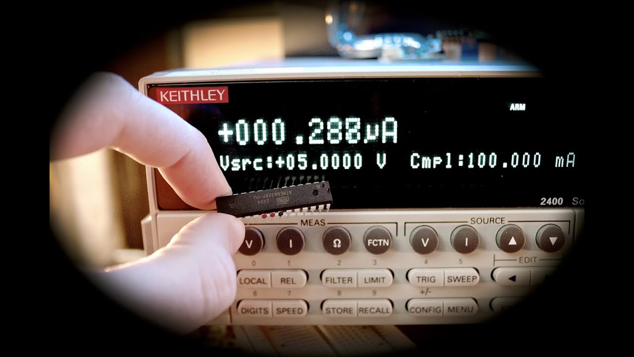
In this video I'll show you (without libraries) how to place the Arduino into a deep sleep state - we'll get this bad boy down to ~0.287uA running the bone stock ATMEGA328P-PU with the Arduino boot loader running at 16MHz with a 5V power supply. I'll show you how to wake up w...
rapid radish
Personally I prefer the various ARM Cortex M chips rather than AVRs, though opinions differ, and there's a lot of Arduino support for the AVRs... software libraries and tools matter a lot for not wasting a lot of your time to get something running. PICs and the MSP430 series are other well-known options.
On the plus side, your feature needs are pretty modest, just I2C and a PWM output for the servo if I understand correctly. So almost any microcontroller will work.
winged olive
Ok - if i understand correctly, Arm Cortex M is another family of chips by another company and AVRs are the standard atmegas and samd21 commonly used with the arduinos. The MSP430 is a TI microcontroller that is also efficient.
I agree - I think the differences between the chips are more aplicable in more complex circuits (other than support and libraries), so I might be better off going with an AVR?
rapid radish
Cortex M is a general processor family that a lot of manufacturers license from ARM to make their own chips with... ST, NXP, TI, Microchip, etc. The SAMD21 is actually an example of a Cortex M0 made by the same company that makes the AVRs.
winged olive
Thankyou so much for your help thus far. So basicallly, the cortex M is a family of processors (like the atmegas) and is then licensed to differnt companies to make a different chips for different aplications, much like how you see tons of different nvidia graphics cards of the same type, but adapted for a differnt use (ie. more fans)
rapid radish
Yep, exactly! The core CPU is generally the same, but different manufacturers will have different add-on peripherals, different amounts of memory, etc.
winged olive
Ok that actually makes a ton of sense, especially how there are so many well developed versions of chips. Alright, so knowing this, I am defintiely going to want to stick with AVR based chips as the VCLN4040 spark fun/adafruit libraries are for them. I guess it comes down between the Samd21 and Atmega328
rapid radish
Just in terms of nomenclature, "AVR" typically refers to the 8-bit processor family like the Atmega, but the SAMD21 is completely different, a 32-bit ARM chip.
Though chips from both families generally have Arduino library support.
winged olive
Oh my bad - we just went over that 🤦♂️
rapid radish
No worries. It's genuinely confusing sometimes, especially since Atmel used to be a separate company before being acquired by Microchip, so their product lines got kind of smooshed together.
winged olive
Oh really! That must have served some healthy competition.]
Ok, I think I will go with some variation of the atmega328, since although the samd21 has a bit better power efficiency, I think it is more likely I will be able to utilize the 328's efficiency since it is better documented.
I think it is very likely my school will allow me to prototype with their PCB miller, but I am woried since the prototype will not have a solder mask. Would it still be possible to solder the components easily?
Especially the VCLN4040 - it's pins are on the under side so I am further worried
Do you have any personal reccomendations for PCB manufacturers, especially for a budget?
I will start learning eagle tonight, but hopefully by the end of tommorow I can have a schematic finished and start to work on the PCB layout.
rapid radish
Soldering the VCLN4040 will be challenging but not impossible... you'll probably want to alter the recommended pad layout in the datasheet to extend them out from under the chip a bit, so you can get at them with your soldering iron more easily.
As for finding a cheap PCB shop, this might be a good starting point: https://pcbshopper.com/

PCBShopper is a price comparison site for printed circuit boards. Enter your PCB's specs and immediately see prices from more than 20 PCB manufacturers.
winged olive
Thankyou for that tool - I spent about 3 hours today calling pcb manufactures from all over, but this tool makes it a lot easier
I almost forgot - according to the datasheet, the servo I am using, the mg995, has a stall current draw of 10 ma. This is way too much so I was thinking I should use a mosfet to turn it off when it isn't being used.
When looking for tutorials for mosfets online, they say to connect the drain to the ground of load (servo), and the source to the ground of the power source. Then I would use the same ground device to power the atmega328 p and connect to one of the pins the mosfet. I could then use a resitor of any size (apparently doesnt matter?) to connect the gate of the mosfet to one of the digital pins
is this right? why does the resisor value not matter?
rapid radish
I always get FET circuits wrong the first time, so I can't give you good advice there. But the resistor value doesn't matter much because a FET is driven by voltage at the gate, so it doesn't require much of any current to activate. (This differs if you have to switch a FET on and off rapidly, in which case you might need to have some decent current to get the gate voltage to change instantly.)
winged olive
Oh ok - how would I know which one to use? I read about using a graph on the datasheet and the current draw to determine this, but it seems a lot like trial and error.
Oh shoot - I actually need to get to bed now... Sorry about that, but thank you so much for the help tonight. I will talk to you tommorow hopefully and I can finish up this over all design.
/layout
Before I go to bed, I am actually going to order the breakout board by sparkfun for the VCLN4040, but can you reccomend any other components for further prototyping of this? I was going to get the 16hz crystal and 18-22 pf capactiors for the arduino, but since I will probably be running at 8 hertz anyways I don't think I'll need it
rapid radish
Let's see. You'll probably want to consult an Arduino reference design to make sure you have all the support components for the microcontroller. Some decoupling capacitors will probably be required, just like on the VCLN4040 board. And you'll want to think about how you're going to connect to it to load software, etc.
Starting from a pre-made Arduino board using the same chip as the one you plan to use could eliminate a lot of potential uncertainty.
winged olive
Ok - I think I will base it off an arduino pro mini or arduino uno, but if I understand correctly they have the same chip - the atmega328p, just in different form factors
So I can just transfer it over
https://www.arduino.cc/en/Main/Standalone This guide specifies using some capacitors - 10 uf for the voltage regulators as well as the 16hz crystal, 18-22 pf capacitor, and 10k resistor. According to this guide, but this guide says I don't need those components if I want to use the arduinos internal 8mhz oscilator instead as a clock source - eliminating the external clock: https://www.arduino.cc/en/Tutorial/ArduinoToBreadboard . Do I need those functions for this design? Does this just mean I can only run it off of 8 mhz rather than 16 mhz?
Open-source electronic prototyping platform enabling users to create interactive electronic objects.
Open-source electronic prototyping platform enabling users to create interactive electronic objects.
stark storm
You don't need the crystal nor padding capacitors if you're using the internal RC oscillator, however to use that oscillator, you'll need to configure the chip to do so, and it's a less-accurate oscillator, which probably won't matter unless you're controlling something timing sensitive (like serially addressed LEDs or high speed serial communication). You can also use a resonator instead of a crystal, which gives acceptable accuracy in an inexpensive, all-in-one part that doesn't need separate capacitors.
winged olive
@stark storm No I don't really have much time sensitive things, bur would a servo need the internal rc oscilator? I would have a VCLN 4040 proximity sensor hooked up to the sda scl and probably a digital input. I would need to program its duty cycle and stuff. I would have the Arduino go into deep sleep mode and woken up by the sensors interrupt pin, where it would then open the gate for a mosfet that allows current to flow to the servo, then telling the servo to make certain movements. Would any of this need the accurate oscillator, or would be it be fine with the 8khz set up? What does an oscillator really do and why would it need these external components?
stark storm
The oscillator provides the CPU clock, which determines the instruction timing. The built-in one is a very simple circuit that's good enough for many uses (and yours sounds like one of them). The external components are to give more choices of speeds, re-use a clock signal from some other circuitry, or provide more accuracy.
Note: it's 8MHz, not 8kHz
winged olive
Ok, that makes sense. So the oscilator basically gives like a refresh rate, and I can use the internal one, but using the cyrstal and capacitor or a resonator just optimizes the performace of this allowing for better refresh rates/cpu power, whcih I don't necesarilly need
If I have pull up resisotrs and my sda/scl connected to 3.3v on my sensor, would I still need to do this again for the arduino?
rapid radish
No, one pullup anywhere along each wire is sufficient.
winged olive
ok good, i thought so but then the diagram of one of the boards had it
 brisk hollow
I'm considering making a wrist watch out of a HDSP-6504 4 digit 16 segment display from 1977.
They're the bubbly type with a pretty cool style.
Quick and dirty 3D render
I want to use the ATSAMD21G18 directly with no multiplexing, though I'm unsure if the M0 chips can drive it directly with the GPIO.
I need at least 20 GPIO pins to do it aswell.
rapid radish
It's going to be somewhat dim driving it from GPIOs. The D21 can only source 7mA out of one of its pins, and the display is specced for 30mA.
brisk hollow
Per segment it only needs 7ma to be driven to full brightness, though that's with a 100% duty cycle aka DC.
25% duty cycle is minimum, so I'm not going to be able to run full brightness
I've tested it with a range of dummy resistors and I've found it perfectly readable at just 0.5ma, at 5ma it's plenty bright so.
Working on traces and bond wires, this is with lens cover.
I really dig the style of these things.
Thus far I'm considering custom PCB with D21, MSA301 for tap sensing interrupts, 8523 RTC with Seiko CPH3225A ultra caps instead of RTC battery.
Along with small lipo with charge circuit and voltage regulator for the 3.3v.
winged olive
@rapid radish Alright, so I think I found a viable buck converter from TI - http://www.ti.com/lit/ds/symlink/tps62240.pdf?ts=1588754698574 . I read through the datasheet, and it seems to have some low power saving modes built in, but I was wonderif if since it is a 300 ma converter, if it draws 300 ma (+quiscent current) even when I am only drawing say 1 ma?
stark storm
No, it only draws the output current times the ratio of output voltage to input voltage, divided by the efficiency, plus the operating current.
winged olive
@stark storm Thankyou for the help. If I may ask, why is that formula used? How did you like ... obtain it? How would I calculate the efficiency?
stark storm
The ratio is just conservation of energy: energy out is roughly the same as energy in, so as the voltage goes down, the current goes up proportionally. However, there's some loss, these converters aren't 100% efficient, so you correct for that too. There's also the power drawn by the control electronics themselves, which is generally a more or less fixed amount.
 sacred hearth
just to add to that, you can look up efficiency in the datasheet.
stark storm
Calculating the efficiency is somewhat tricky as it depends on both the components chosen and the amount of current drawn, but the manufacturer generally includes useful information in the data sheet like this.
winged olive
@stark storm Thankyou so much for the help. I did see that graph, but was kind of confused - Is the V sub I the input or output voltage? Further, if none of the voltages I am using are on that graph, how might I calculate it? I don't necesarily need to know how that works for this project, but would still love to know (or if you could point me to any good resources) I am going to input about 5-6 volts, and output with 3.3. I will be supplying the arduino and sensor with 3.3 v and the servo with whatever comes out of the servo, using 4 C (1.5v) batteries. With this set up, would it be more efficient to just connect two of the C batteries (2.5 - 3v) to the arduino and sensor, and then connect a third in series (instead of a fourth) that would all be wired to the servo? I think I would need a diode or two to make sure that the third battery doesn't supply 1.5 v to the arduino and sensor too. I don't know, this was just a thought too minimize costs, and to only use 3 batteires instead of 4 for saving space, but I think I may also decrease efficiency by not being able to use the full capacity of the third battery (first two would drain quicker).
rapid radish
The V_I is input voltage, so it'd be 5-6V in your case. The datasheet doesn't have a precise graph for your values, but mostly it's the ratio that's the key driver of efficiency, so 6V->3.3V should look similar to the curves for 3.6V->1.8V or 2.3V->1.2V, more or less.
You probably don't want to split your battery pack like that, since as you say you'd end up with some weird uneven draining.
winged olive
Ok, yeah that's what I thought
Ohhh does V_O on the table mean voltage out, so the 3.6 v curve is probably most aplicable?
rapid radish
Not sure what table you mean, but yes, V_O is the output voltage.
winged olive
As in the Key on the bottom right says V_O (i thought was V_0) = 1.8 v, so then the 3.6 v curve would be beest for efficiency.
(most aplicable)
rapid radish
Exactly.
winged olive
Ok cool!
I have been getting a bit of school work lately, so I probably should get to bed, but hopefully in the morning I can find the right mosfet and draft a schematic. Do you mind if I add you as a friend? You have been insanely helpful - still blown away by what you do for everyone.
rapid radish
Sure, feel free. This is a nicely helpful community in general, plenty of good people here.
winged olive
@rapid radish Alright, submitting an order to spark fun for a bread board protype - I already have arduinos that I can get their atmega328's from, but want to try out the pro mini to consider going with the atmega328pu oposed to the p
Anything else you might add?
rapid radish
Do you have some 0.1" header pins already, or do the boards come with them?
winged olive
Ohh almost forgot those - I need those anyways
Also, incase I want to change up the circuit with transistors, what is the difference between Npn and PNP?
rapid radish
Transistors are my weakness, actually... I always get confused by the different sorts. 😅 Give me a nice clean digital-logic signal any day!
winged olive
Hahaha I can understand that - I've had like 3 projects I have backed out of because I couldn't get my head around mosfets and transistors, but I think it is time I finally learn them lol
rapid radish
Same, yeah... I need to get some flash cards or something and just sit down to memorize them.
brisk hollow
Npn and pnp are essentially the polarity of a transistor
winged olive
Yeah same haha. I think NPN is the right one because sparkfun used it in their tutorial and I am too tired to check everywhere, so I added it with some 1k ohm resistors to limit the current
Oh really?
So they function the same haha?
brisk hollow
I'd start with mosfets tho, they can be used in most places and have more ideal characteristics
No forward voltage drop and the gates are pure voltage driven
Bipolar junction transistors have a relationship with the curry you drive them with and the current going through them and all kinds of other things
Just do tie mosfets gates directly to gpio pins, use a small resistor like 5k between
Gate capacitance can be rough on signal level gpio
winged olive
Oh ok - I am building the circuit SMD, but didn't realize mosfets didn't have a relationship with the current
what do you mean by "do tie mosfets gates" is that a typo or a type of mosfet lol
Lastly, how would I know the range of resistors I can use to the gate? Would a 10k resistor work the same?
brisk hollow
Don't tie*
10k works fine, it's just about reducing the peak current the gpio has to push
winged olive
As you can see I am not that knoledgable when it comes to this stuff, but could you also explain the gate capacitance (what is gate capactiance) and how does it affect the signal level - I though Gpio pins were just a high or low?
Oh that makes sense - so like using a resistor for an LED
brisk hollow
Gate capacitance is the behavior of mosfet gates that act like a super small capacitor
A capacitor looks like a dead short or close to it when you try and charge it really fast.
The gate resistor is there to limit inrush current
winged olive
Oh that's cool! I will be sure to put a resistor
Last question before I get to bed - can I use a 10 k potentiometer and use it to test different values of resitors if I don't have the exact resitor? As in using a multimeter directly to the probes of the pot and measuring resistance
brisk hollow
You don't need to really, just use 10k and you're fine
rapid radish
Tuning the resistor value can matter if you're rapidly switching the FET on and off, so the time-scale of capacitance makes a difference. If your case, since you are just using it as a power switch, almost anything should work.
But to answer your question, yep, a potentiometer can be used as a variable resistor for testing that kind of thing.
winged olive
Ok, yeah. I might be switching the sensor on and off later, but I doubt it because there is a capacitor so it would probably not do so well haha
winged olive
@rapid radish I was looking the datasheet of the buck converter - TPS6224x, as I am doing the schematic, when I found this:
8.3.3 Enable
The device is enabled by setting the EN pin to high. During the start up time tStart Up, the internal circuits are
settled and the soft start circuit is activated. The EN input can be used to control power sequencing in a system
with various DC-DC converters. The EN pin can be connected to the output of another converter, to drive the EN
pin high and getting a sequencing of supply rails. With EN pin = GND, the device enters shutdown mode in which
all circuits are disabled. In fixed output voltage versions, the internal resistor divider network is then disconnected
from FB pin.
The problem is, this powers the arduino, but to turn it on, I need the arduino to put the enable pin high
How would I get around this?
would I be able to use the 6v from the batter to enable it high, or is this a bad idea
rapid radish
Yep, that's perfectly reasonable. You can see in the "typical application schematic" in the datasheet that they just tie EN to the VIN in order to have the regulator turn itself on automatically when voltage is applied.
winged olive
Oh awesome
That section is actuallly really helpful
Question: It talks about inductor selection has a direct effect on ripple current, but what is ripple current? I don't understand most of the online expanations
Do you think I could just use this circuit, except change the resistor values to make the circuit 3.3 v and the input cap to 10 uf? Or do I need to worry about ripple current and ripple voltage and calculate the optimal caps/inductor values?
I think I would do a 810 k and a 180k resistor
As it says: 9.2.2.1 Output Voltage Setting
The output voltage can be calculated to:
with an internal reference voltage VREF typical 0.6 V. (2)
To minimize the current through the feedback divider network, R2 should be 180 kΩ or 360 kΩ. The sum of R1
and R2 should not exceed approximately 1 MΩ, to keep the network robust against noise.
rapid radish
So, a buck converter works by rapidly switching voltage on and off to "charge up" the inductor and then let it relax, so the average output is lower than you started with. During that process, the current will vary a bit on top of its average value, and that difference is a ripple on the steady state. The output capacitor mostly filters it out, but it affects what inductor value you pick to avoid it getting too large.
Those resistor values look good, too.
winged olive
Oh thankyouf or the explanation - makes a ton more sense than any online resources
rapid radish
(The explanation is a bit inaccurate, but somewhat intuitive, at least.)
winged olive
Do you reccomend I calculate the values for the inductor or do you think I should be fine with the example circuit values?
Because I really am having trouble understanding the Inductor selection section
rapid radish
I'd just go with one of the suggested parts, yeah.
winged olive
Ok good - I tried calculating it but there is just so many values I have to find then research, most of which I don't understand
I am starting to slowly build the schematic, but there are many different types of these components. For the sensor, I just went with the cheapest type, as it looked like the only differences were pin spacings, but for this regulator, it doesn't exactly specifiy the differences
On page 20 it has a list of the different types on a table, but for many it doesn't seem like there are any differeces other than the name
rapid radish
I sympathize, yeah... Component selection is not always easy.
winged olive
Is there a reason for this - can I just go with the cheapes on digikey or should I read through every single one haha
rapid radish
Watch out for the exact part number: some are fixed-voltage instead of adjustable.
winged olive
How would I know which ones are fixed?
rapid radish
But a lot of the difference is how many are in a reel or tray, which you won't care about.
winged olive
Yeah I don't really as I am only making 50-100 of these, not like 2000
I understand there are three main different types - the TPS62240 TPS62242 TPS62243, but I cannot find on the document where it talks about these individiduallly and there differences
Are there more doucments I am missing?
rapid radish
Section 5 gives the table in the datasheet.
winged olive
Oh jeez - I am dumb. It was literally at the begining
Ok, so I just need to find a tps62240, and the numbers/letters after that don't necesarily matter for me?
rapid radish
Some of the smaller differences are actually obsolete: TI used to have separate part numbers for leaded and lead-free "green" parts, so they keep that for compatibility even though all the parts are lead-free now.
winged olive
Ohh that makes more sense
I was looking through and it talked about lead vs lead free but then all of them are lead free haha
stark storm
The difference between -DRVT and -DRVR is just reel size, as Ed pointed out, which doesn't matter to you since you're getting cut tape anyway, so you may as well get the cheaper 296-27028-1-ND
winged olive
@stark storm Yes, I see that now. I was litrally about to ask if that was correct - you read my mind! Thank you guys so much on helping me out with this
left acorn
Aside from the obvious horrible soldering job why don't the header pins work, I tried running the standtest with the appropriate parameters and nothing
rapid radish
That solder blob looks like it's bridging the data and power pins.
left acorn
I removed the blob bridging the data and power pins yet it still doesn't work :/
winged olive
When I power the atmega328p at 3.3v, will the digital pins also output 3.3v, or will they output the exact same as if I were powering a full size arduino with 5v? (for the mosfet I need to know how many volts and amps I can supply the gate) I think from what I have read, it essentially works the same, except lower clock speeeds
rapid radish
The GPIO will also be 3.3V in that case. Possibly the pins may have lower current limits too than when running on 5V.
winged olive
Oh ok - that makes a bit more sense than it having a bunch of step ups and stuff.
I am going to bed now, but although I am still doing research about the different parameters for mosfets and what to look for/calculate efficiencies and heat loss, I am looking at this mosfet: https://www.ti.com/lit/ds/symlink/csd13380f3.pdf?&ts=1589179436735
It is really the only mosfet TI sells for battery applications, but I think since there are 27k + mosfets on digikey I will just try to stick with TI for the sake of not going insane. That is if I find this is a good option, but I am still looking into it.
@brisk hollow It seems you know quite a bit about mosfets. Do you know of any good online resources that explain them and the datasheet parameters well?
rapid radish
That looks good spec-wise to my uninformed opinion, but you should think about that package a little bit, as it may be pretty challenging to hand-solder.
winged olive
Could you elaborate on this? I am haven't done any SMD soldering yet, so I am not necesarily familliar with the challenges/limitations
rapid radish
Mainly it's just really small. The whole chip is like 0.7mm.
winged olive
Oh jeez that is really small - like the width of my finger nail small
Wow I doubt I can solder that even with a hot air gun
Maybe I should look at some other vendors, any reccomendations?
rapid radish
I've sometimes had good luck with Diodes, Inc.
brisk hollow
Take a to220 mosfet if size isn't a issue
Also keep in mind not all mosfets can be driven with 3.3v on the gate
They might go into their linear mode
stark storm
I'm very fond of TO-92 MOSFETs for ease of soldering, but TO-220 is easy too (just bigger, and appropriate for high power switching)
brisk hollow
Replaced dead mosfets with infineon direct fets.
Mounted upside down.
Absolute state of bodge'd
winged olive
I more looking at smaller SMD mosfets for battery aplications like this one. I was trying to stick with TI as they are local and I have many friends who's parents work there and could possibly help me (we'll see.) If I hot air reflow the CSD13380F3, would it still be hard to solder, or is it much easier?
It will be driven on by 3.3v with most likely a small amount of current from a 3.3v arduino for a short bits of time - probably at the longest 10 seconds. I think the servo draws at the highest around 1.5 a, but I doubt this system will draw close to that
brisk hollow
Looks like that fet will work very well at 3.3v, pretty unusual to see a mosfet that operates down to 1.8v without going into the linear region.
I think that fet should be doable to solder with a heat gun, I've done smaller. Though that was with electronics microscope.
winged olive
@brisk hollow Would it necesarily be sustainable for making 50 of them? If I used a microscope such as: https://www.amazon.com/Jiusion-Magnification-Endoscope-Microscope-Compatible/dp/B06WD843ZM/ref=sr_1_3?crid=1KLN63VUDK66A&dchild=1&keywords=digital+microscope&qid=1589264535&sprefix=digital+micr%2Caps%2C183&sr=8-3 would I be able to do it? I am thinking about building a PCB oven or something, but I might be getting a bit ahead of myself
winged olive
TI has a line for power efficient applications, where they have also have a 30v n channel mosfet and 2 12v p channel mosfets: http://www.ti.com/power-management/mosfets/n-channel-transistors/femtofet.html . I still need to look into it, but I think they aren't nearly as efficient as the one I listed earlier and are not optimized for battery applications. If I understand correctly, P channel mosfets are not as efficient as their main difference is they go on the postivie line vs. the n channels go on the negative. I think this is called sinking if I remember correctly from last week
Am I correct about N vs P channel mosfets?
stark storm
P-channel MOSFETs are often used to switch from the positive rail (by bringing the gate low), thereby sourcing current. N-channel MOSFETs are often used to sink current to the negative rail.
winged olive
Would this mean that N channels are more efficient than P channel mosfets?
(For a digital switch)
rapid radish
Not necessarily... The efficiency would mostly depend on the "R_DS on" value.
brisk hollow
N channel fets are usually lower on resistance than P channel.
Something to do about being easier to manufacture, Old Germanium BJTs which were the first power transistors the PNP type was easier to manufacture and much more common.
winged olive
Thanks for the clarification. I have had a very heavy school load this week so I haven't really had a chance to look in depth at this
 upbeat fox
Is anyone succeed to make Disney RFID Magicband working a microcontroller?
winged olive
How does this look? http://www.vishay.com/docs/63302/si2342ds.pdf
stark storm
Looks similar to the very popular Si2302 / A2SHB
winged olive
How would I find a schematic layout for eagle of it (Si2342DS)? It isn't in the eagle library so how would I go about using it?
rapid radish
If you can find a library part in some other format, UltraLibrarian is a good tool to convert to Eagle, and they may have it in their catalog to start with.
Otherwise, you can make a custom Eagle library, which should be fairly easy by piecing together a FET symbol and a SOT package from other parts and just assigning the pins correctly.
Or you may be able to find a similar part which already has exactly the same package and pin assignments and just use that, then specify the part number in your board bill of materials to be different.
winged olive
I found an online library: https://componentsearchengine.com/search.html?searchString=Si2342DS , but the website is super sketch. I keep hearing about packages and 'SOT' with different numbers, what do these exactly specify?
rapid radish
"Small Outline Transistor". It's a spec for chip size and pin shape so that parts from different manufacturers can be handled uniformly. The numbers give sub-types for particular numbers of pins, etc.
winged olive
Oh so packages are like a standardization for the parts to fit to? That makes a ton of sense and isactually pretty smart
rapid radish
Yeah, not everything is standardized, but the simpler and cheaper the part, the more likely it is.
winged olive
Oh, well atleast some are haha
@rapid radish I don't necesarily want to include an ftdi circuit in my board, so would I be able to use this tutorial - https://www.arduino.cc/en/Tutorial/ArduinoToBreadboard and break out the pins specified? Does it still apply to the atemga328p-au?
Open-source electronic prototyping platform enabling users to create interactive electronic objects.
I found the pins needed (for 8k version) on that turotial and mapped them out: Pins to keep broken out (on the atmega328p – pu)
(for boot loader)
Pin 1: PC6
Pin 17: PB3 (digital pin 11 (pwm))
Pin 18: PB4
Pin 19: PB5
Pin 1: PC 6
Pin 2: PD0
Pin 3: PD1
Would these still work for the au?
rapid radish
The pin numbers probably will change for the -AU. For instance PC6 is on pin 29 in that package variant instead of pin 1. But the same pin functions should apply.
winged olive
Ok awesome - I am almost finished with the schematic. Would you mind looking it over when I finish?
rapid radish
Sure, happy to. I haven't done an AVR board myself, so there may be some stuff I won't catch, but I can see if anything otherwise looks strange.
winged olive
Awesome thanks!
winged olive
Do you know if the footprint for the tps62240drvr - the voltage regulator I am using would be the same as the other packages? They have different footprints for the other types/packages of it, but not the drvr version: https://www.snapeda.com/search/?q=tps62240&search-type=parts
Download schematic symbols, PCB footprints, pinout & datasheets for tps62240. Exports to OrCAD, Allegro, Altium, PADS, Eagle, KiCad & Pulsonix.
Would it be okay to just use one of the other packages?
rapid radish
It looks like the DRVR is the WDFN-6 package, so you can probably use any part variant of that type, but you wouldn't want to use a different package like the TSOT-23, as it would be a different size and pad layout.
Note that the WDFN-6 has an exposed pad under the part, so if you're hand-soldering things, the pinned packages like the TSOT might be easier.
 quasi ice
I am not sure, if I am writing in the right channel
I have a BLE UART FRIEND and I managed to add two costum services. The first one has one costum characteristic.
Now I wrote my own App and want to write to this costum characteristic
but I am not able to write
I am able to read the data
I am writing in Android
void sendMessage(byte[] message, String uuid_se, String uuid_ch) {
if (mBluetoothAdapter == null || mBluetoothGatt == null) {
Log.e(TAG, "BluetoothAdapter not initialized");
return;
}
mCustomService_w = mBluetoothGatt.getService(UUID.fromString(uuid_se));
if(mCustomService_w == null){
Log.e(TAG, "Custom BLE Service not found");
return;
}
mWriteCharacteristic = mCustomService_w.getCharacteristic(UUID.fromString(uuid_ch));
mWriteCharacteristic.setWriteType(BluetoothGattCharacteristic.WRITE_TYPE_NO_RESPONSE);
synchronized (this) {
if (isSending) {
messageQueue.add(message);
return;
}
isSending = true;
}
mWriteCharacteristic.setValue(message);
boolean status = mBluetoothGatt.writeCharacteristic(mWriteCharacteristic);
if(status == false){
Log.e(TAG, "Failed to write characteristic");
}else{
Log.e(TAG, "Message sent");
}
}
In the log is written: Log.e(TAG, "Message sent");
but the following callback is never called
public void onCharacteristicWrite (BluetoothGatt gatt,
BluetoothGattCharacteristic characteristic,
int status) {
if(status == BluetoothGatt.GATT_SUCCESS) {
byte[] message;
Log.e(TAG, "SENDING DONE");
synchronized (this) {
if (messageQueue.size() == 0) {
isSending = false;
return;
}
message = messageQueue.remove(0);
}
mWriteCharacteristic.setValue(message);
mBluetoothGatt.writeCharacteristic(mWriteCharacteristic);
}
}
I wanted to ask, if your Adafruit BLE firmware needs a specfic format to wirte
because I am writing following strings '#p.0'
I confingured it so:
error_identifier(atcommand_send("AT+GATTADDSERVICE=UUID128=00-11-00-11-44-55-66-77-88-99-AA-BB-CC-DD-EE-FF", &se_brightness_id)); error_identifier(atcommand_send("AT+GATTADDCHAR=UUID=0x0002,PROPERTIES=0x08,MIN_LEN=1,MAX_LEN=15,VALUE=#p.100", &ch_brightness_write_id));
but I am able to read following characteristic
:
error_identifier(atcommand_send("AT+GATTADDSERVICE=UUID128=f3-64-ad-c9-b0-00-40-42-ba-50-05-ca-45-bf-8a-bc", &se_adcdac_id));
error_identifier(atcommand_send("AT+GATTADDCHAR=UUID=0x1401,PROPERTIES=0x02,MIN_LEN=1,MAX_LEN=15,VALUE=#d.3.3", &ch_adc_read_id));
quasi ice
i changed following line, but no change mWriteCharacteristic.setWriteType(BluetoothGattCharacteristic.WRITE_TYPE_NO_RESPONSE); to mWriteCharacteristic.setWriteType(BluetoothGattCharacteristic.WRITE_TYPE_DEFAULT);
quasi ice
i would really need help
quasi ice
i found something interresting
the nrf connect app also fails to write on the characteristic with Android 9.0
on a Samsung J3300
on my Sony E4 with Android 4.4.4
 night gale
hi im trying to set it up where each button on the membrane four button triggers an arrow key on my pc, so if i press the 4 that triggers up, and if i press the three that triggers down, what parts from adafruit should i buy to connect the 4 button membrane to a pc through usb so i can use the buttons as key strokes?
thank you for reading my question!
stark storm
Perhaps the cheapest (and smallest) option would be a Trinket M0. Another possibility would be one of the ItsyBitsy boards.
night gale
@stark storm thank you i'm looking at both of them, so i just buy one of these they have to be ove 10 to 15 feet away from, what do i use to connect them far away is there a product that I can buy from Ada fruit?
 wintry quarry
hi guys! i'm new to discord and i'm using a desktop and joined a voice chat in another server but i can't figure out how to leave pls help
o wait i figured it out
but yes the trinket M0 is a good idea lol
stark storm
Connect to the buttons or connect to the computer?
night gale
either or it needs to be low key so it'd be best if the trinket MO was far away from the buttons and just had lines from the 4 buttonTrinketMO membrane really run a really long cord,
is there a limit to how long the wires from the button to the cords can be? would the signal from the button make it 15 feet to the TrinketM0?
stark storm
Should be able to run long wires, since they're just simple switches. If there's a noise problem, you can use smaller (like 10kΩ) pull-up resistors.
light wigeon
Hello, sorry for the sketch but I just thought it might help explain what I'm trying to do!  Anyhow, I was wondering if anyone knew how to add something like this to SPI displays using an adafruit circuit? I wasn't even sure how to go about searching for this on my own so I apologize if this is something simple that's going over my head. I do not know how to cue different animations, and do not have any extensions that would allow for this function yet, but I would be willing to purchase them if needed. Hence the
  imagined ✨ finger buttons which cue different animation loops to replace the default animation. Any help or resources are appreciated!
 exotic tendon

Adafruit Learning System
User friendly guide to CircuitPython's native display library - displayio.
you could create some animations and switch between them with switches
light wigeon
No, but I just skimmed the article and it seems very useful! Thank you. May I ask how you switch between the animations?
exotic tendon
a contact closure could trigger hiding or showing a Group for example. what kind of display do you have?
(how "fast" you can animate something depends on the type of display and how fast your board is)
light wigeon
I have all parts listed here! https://sudomod.com/spooky-arduino-halloween-eyes/

Arduino code: https://github.com/wermy/Uncanny_Eyes STL files: https://www.thingiverse.com/thing:3184048 Snap-fit case Fusion 360 tutorial by Noe Ruiz from Adafruit: https://www.youtube.com/watch?v=VVmOtM60VWw Parts…
exotic tendon
looks good, you can create your own pngs to animate?
light wigeon
Yes, that is what I was planning - here's a quick example animation I did a little while ago. Just an alternation between 3-4 different expressions
exotic tendon
perfect, you can more or less drop them in the code you have
then use digital pins to read switches instead of changing them after x amount of time
light wigeon
That's great news, thank you so much for your help!!  I'll check out those digital pins and go back over the article rn
exotic tendon
actually you are using arduino, not circuit python so iggy that link for now
light wigeon
 Oop- okay
https://www.arduino.cc/en/Reference/LiquidCrystal Is this similar somehow?
Open-source electronic prototyping platform enabling users to create interactive electronic objects.
exotic tendon
sorry, that is a CP board, iggy my iggy 😦
light wigeon
Lol alright, no worries :b
exotic tendon
one of the example sketches is for arduino
the link you sent above is for a text type LCD screen, the one listed in spooky eyes is the type you want
light wigeon
Ah you're right, I'll pay attention to that next time haha
exotic tendon
there are many types of displays, some fast, some low resolution (text), some use more battery power , some less, important things to consider on a wearable (so you don't end up lugging around a car battery 🙂 )
light wigeon
skdjfdskj Yes that sounds ideal
exotic tendon
do you have those parts already, or just checking for suitability?
light wigeon
I have every part listed from the sudomod 'Spooky Arduino Halloween Eyes' tutorial, except I replaced the smaller SPI displays with https://www.amazon.com/HiLetgo-240X320-Resolution-Display-ILI9341/dp/B073R7BH1B these
Nothing is put together yet though, I'd like to be sure what I'm doing first
exotic tendon
there is a learning curve, but once you get the hang of it your imagination is the limit
your pngs are 240x320?
(the original was 128x128)
light wigeon
I could make the pngs fit those dimensions pretty easily, I believe? Also, I hope that I do reach that level of understanding sometime!
exotic tendon
just pointing out - if you get it all connected and run the example the eyes may not fill the (bigger) screens
light wigeon
Oh okay thank you for pointing that out, the example is just for reference though, I'll work on something more fitting for the display soon!
exotic tendon
are you pretty new to coding?
light wigeon
😓 Unfortunately, yes sldkfds
exotic tendon
be sure to take your time wiring it up. Unless you get power backwards there is little you can do to damage things (may not work, but no permanent harm)
do small things at first, get your graphic to show up for example, before trying to animate it, things will gradually make more and more sense
then when you are done you'll have 1000 lines of code and dazzle the neighbors 🙂
light wigeon
All I've ever wanted!! 😌 Lol
Lol
Thank you again, I really feel a lot more prepared to work on this project with your advice!
exotic tendon
it's amazingly complicated but thanks to the way Adafruit and others support it, it becomes easy!
(No, i don't work for them 🙂 )
light wigeon
SDKLFJS well I suppose I'll take your word for it :b
exotic tendon
here's an example to get used to working with switches https://learn.adafruit.com/circuitpython-essentials/circuitpython-digital-in-out

for your project, a switch can be as simple as touching 2 wires together
light wigeon
 I hope it is truly that simple
exotic tendon
once you are used to simple examples, you start to see how they work and start to combine the features into 1 program
you can make it not work with code mistakes but it won't damage any of the parts, feel free to experiment in code
and back to an earlier point, you'll need a pretty good battery to drive those displays (but much smaller than a car battery!)
light wigeon
Sounds good! As for the battery, the goggles are going to be a part of a larger mask, so I anticipate that there will be plenty of room should I need it, and parts won't be visible externally
exotic tendon
yup, small enough to hide in a mask
left acorn
Would using conductive copper tape work with an adafruit neopixel jewel
exotic tendon
@left acorn yes as long as you keep the tapes from touching, it'll handle the current
stark storm
I used copper tape around the perimeter of this prop as both a conductor and a light shield for an LED ring, it worked fine.
 normal sequoia
hey curious if anyone know of any fitness tracking band with public bluetooth APIs
short fjord
Does anyone know how I can adjust the 'interrupt' for the MPU-6050? I want it to wake up my arduino when it is moving, but right now it's always triggering the interrupt
 humble shale
I dont think the interrupt pin in the MPU6050 can be used for waking up the device
it is for telling the mcu when the MPU6050 send data
humble shale
because it send the data at a certain frequency
and thus it send the interrupt signal
 tame parrot
ok so
raspberry pi decided to boot now. It previously didnt want to. Today i just decided to try, without doing anything to it or the sd cards and it booted on both of them
one sd card has kali and the other got Raspbian
can someone explain to me why this is so?
 inland olive
 grand hinge
@normal sequoia Many discrete sensors (i.e. a heart rate sensor or a pedometer, but not necessarily combined ones) use bluetooth APIs defined by the Bluetooth SIG, and Adafruit has circuitpython libraries for interfacing with many of them. If you're talking about something more like a fitbit, it's slightly more complicated. There is a way, but you need to use their web API. I've used it once or twice when I was just messing around, and it actually works pretty well, although it's not bluetooth, so you actually need an internet connection, making it more difficult to use in portable projects, especially those that involve microcontrollers.
 limpid eagle
well
@pliant fjord
it doesn't worth your time
just buy another one or use speakers
 pliant fjord
Hi I hope I'm right in this channel, I just thought about trying to repair this Sony bt headphone,
The speaker on the left side does scratching noises sometimes, but when I hit it, it does work for a while again, does anyone has an idea what I could look for?
I just opened up the faulty side.
stark storm
That generally means a loose connection, either in the speaker itself, the wiring, or (if you're unlucky) inside a component.
pliant fjord
Should I try to exchange the speaker wires first?
stark storm
I'd suggest poking individual wires while listening for scratching noises. When you find a wire that's sensitive to poking, resolder or replace it.
 spare igloo
Hi, i have a problem with Flora V2 and Arduino IDE, can someone help me please?
I cant select the port linux mint, I've tried to press the reset button after clicking upload and it shows the port but it disappears
 knotty depot
making a wearable LED face mask with 40 neopixels on it, what would be a good mAh to aim for a power source?
rapid radish
Depends on how many you expect to be lit, and how brightly. Full-on white is about 60mA each, so that would be 2400mA total for an upper limit.
 upper bolt
I just saw an awesome neopixel mask on reddit. actually the guy was asking me how to best affix the LED strips. He will probably vacuum seal it, which I'm a bit against as it will be hard to fix. Any suggestions?
stark storm
I'd probably make a clear layer and screw it on top of the LEDs.
light wigeon
You could paint it with several layers of transparent paint.
knotty depot
where should i look to find thin black fabric that LED's can shine through but concealing the strip itself?
 royal fern
would panty hose work?
upper bolt
maybe!
Jackson, a knit fabric should work fine. if you can just take your cell phone with camera light to any store, browse around. a thin scarf might be good
 amber widget
@knotty depot any fabric store will have something, as well. Depending on the LEDs, many are incredibly bright, so the material won't need to be too thin.
Exactly what boomtown001 said.
upper bolt
👍
panty hose on top of the mask, and then maybe hot glue the edges so that the back can be cut away. I think I'll give this a try!
stark storm
You can use black grid cloth https://www.canvasetc.com/product/ripstop-gridcloth-fr-black/ black single net, or black speaker grill cloth: all pass (some) light, diffuse it some, and reflect little.
knotty depot
found a spare black facemask lying around, it actually fits nicely on top of the other mask and when i shined a flashlight to the mask it seemed pretty good
just cut out the spare parts and then i can finish up the electronics, then put it on the inside of this mask
upper bolt
how's it looking?
the black facemask with LEDs under
the pantyhose - it would work well on a totally convex surface. but in this case, on the nose bridge, that's a place where they aren't sticking very well, and the nylon panty hose aren't helping. maybe hurting a little by putting tension on the other areas
maybe I need to push tiny thumbtacks in the exact right spots so as to not-ruin the circuit, lol
maybe I should use double sided puffy tape? I hate that stuff for no good reasons that come to mind. but it might be best here
knotty depot
https://cdn.discordapp.com/attachments/680902064691347504/727961019153907793/image0.jpg seems to work ok, in the photo keep in mind some parts of the strip are not pressed up against the mask and it makes the lights a little more blurry

ignore the other stuff littered around my desk
 stark storm
I wonder if the hook side of hook-and-loop fastener would get it to stay in place.
royal fern
(Jakson) ALL OF THE BATTERIES!!!!
haha!!!
or clear double sided tape?
velcro always make that sound....
and i wouldnt suggest hot glue with panty hose, unless you are into burning your finger tips!!!
or, you have a toothpick you can trim down......
or a box of them....
knotty depot
lol all of those batteries in the background are for a coilgun project ive been working on, but stopped because i couldnt get access to a 3d printer cause of covid
knotty depot
buttons arrived today
just need to wire up the buttons and then i can seal it up and get to programming
royal fern
hehe....now if i could just make a BFG.....
knotty depot
for some reason the arduino sometimes stutters and turns off if i jostle the strips, i cant seem to find any loose solders, the power to the LED strip is stable, but the arduino sometimes shuts off
 queen beacon
Quick question before I do something apocalyptically stupid.
I want to get the micro LiPo charger for embedding in a project driven by a Trinket. I assume I just connect BAT to BAT and GND to GND and then I'm good to go, and it won't somehow blow out the Trinket by charging and running at the same time?
I'm just weirdly paranoid about some things.
rapid radish
Charging shouldn't be a problem, but which Trinket do you have? The 5V one wouldn't be able to run off a lithium, and honestly it would be a little marginal even for the 3.3V one, since there's some dropout voltage in the regulator... as the battery runs low it'll typically dip below the needed voltage.
queen beacon
3.3, which is supposed to be able to run off the 3.7v batteries.
I think the regulator can be disabled. Probably for when you're only ever running from battery.
Nope, I'm wrong. It's the Feather that can disable the regulator.
But now that I look at the spec, I was worried for nothing. It specifically says that you can put 3-6V in on the BAT pin, and it'll come out the regulator at 3V. I was mostly worried because I don't know the voltage put out by the charger, and didn't want to send too much voltage where it didn't belong.
rapid radish
Typically lipos will charge at 4.2V maximum.
queen beacon
So, well within limits. Great!
Now... Just gotta wait for my desired battery to be stocked either on Adafruit, or Digi-Key.
Or go crazy with this, and shove one of the 2200mAh cells in.
Which would be all kinds of overkill. I think I'll stick with the 350mAh one.
knotty depot
Last time I tried charging LiPo batteries I blistered my thumb
Pro tip: don’t press your thumb against the circuit while it’s charging an unstable LiPo battery
light wigeon
How do I turn ultrasonic distance that it detects to voice or speech
stark storm
I'm not sure that's possible
light wigeon
Oh ok thank you
stark storm
Also, please don't spam the same question in multiple channels
upper bolt
@knotty depot awesome progress , I'm interested to see where you store the board and batteries. what are your plans? Also, I'm not sure the best way to get consistent diffusion for that mask. One thing I've done is use cotton "batting", like cotton filler for jackets. Put it on top of the LEDs. but that'd make it a lot harder to breathe in this case
if you don't care about breathing, then bubble wrap could work well too
knotty depot
The board is small enough there’s a small gap on the side of the mask I can fit it in, and the battery I plan to have run down your neck and probably clip onto the inside of your shirt collar @upper bolt
Although right now I just moved so I’m still setting my workshop up again
upper bolt
yerk! good luck with the move, i hope its speedy
knotty depot
thanks
the LED mask will be a separate mask, that can be easily fitted over any typical mask
so the inner mask can be easily washed and etc
upper bolt
I'm trying to setup a wire frame mannequin with LEDs, that are controllable over the internet, so that I can "work" with others online. put a dedicated camera on it. so far it's a lot of learning for me, will take awhile
ah right, that's good. then can use disposable even
knotty depot
oooo thats nice
upper bolt
if you can get a sensor integrated with your mask, will be super cool. just something that people can interact with a little
knotty depot
an idea i had was to put a small microphone inside
upper bolt
like "if they get too close it turns red", or some buttons on a cable
oh nice! lots of stuff to do with sound
knotty depot
mhm
i just need a hat with an ultrasonic sensor on a motor and i can get a sonar system of everyone around me
lol
upper bolt
we did a project called "center of attention" where my tie got brighter and brighter as long as I kept talking. then died as soon as I let someone else speak up, lol was fun
knotty depot
how were you able to differentiate between your voice and other's voices?
upper bolt
the mic was pressed to me and sensivity was low
if someone else shouted they could get it to turn on
I wanted to start learning how to use contact mics, but just pressing it on my neck was good enough, for the time I had
oh I had like a cotton cover on it too. a pair of mittens cut up that formed a barrier against other people's sounds. it helped a little.. I think the pressure helped more though
knotty depot
neat
royal fern
@knotty depot just a thought...maybe some "horns" on the top could hide a few components?
knotty depot
wdym?
royal fern
like the batteries?
knotty depot
i fear if the batteries were directly attached to the mask it might pull the mask down
royal fern
maybe make it into a skull cap?
knotty depot
eh
royal fern
like a full head VS just a mask.....maybe make top support as well?
so, what does it look like so far?!?!?
knotty depot
right now its just a simple matrix with a micro controller and a pack of 3 AAA batteries
8 pixels long 5 pixels high
royal fern
so, what if(just thinking out loud) you did something like Yondu from Guardians of the Galaxy, and just did something up top(to hold the goodies) and strap it around the sides to the back?
knotty depot
that could work
royal fern
😉
just at the back with some velcro, and some stretchy material, so that "one size fits all" and stuff.....
upper bolt
a top-pocket would be cool
light wigeon
could it be possible to make some sort of ar lense that just uses tiny screens and cameras instead of projecting an image on a lense?
or would that be too weird for your eyesight?
or is this the wrong channel for this?
rapid radish
Some sort of lenses or optics are usually necessary to have the image at the proper focus. If you just have a screen an inch from your eyeball, it'll be blurry, the same as holding a piece of paper that close.
light wigeon
ah already have those from some old iphone vr holder
rapid radish
But generally the camera-and-screen arrangement is called "electronic see-through" AR as opposed to "optical see-through".
Or "video see-through".
light wigeon
ah thank you
 pulsar badge
Hey Guys! I'm currently working on a design project for my Year 11 Computing class, the concept is to create an RFID chip/tag, that stores medical information for first responders to use, It would be awesome if you guys could help me out by taking a 2 minute survey, Thanks! 😁 here is the link: https://www.surveymonkey.com/r/TRZZ9P3

Take this survey powered by surveymonkey.com. Create your own surveys for free.
 bold hill
I have two 24 neopixel led rings that are acting weird. some of the pixels are white when they should be a color. I thought they were just RGB led's but the RGBW strandtest wouldn't work either.
rapid radish
Is there a pattern to how they are behaving? Like, are they always white, even when they should be black, or do they only light up white when you set them to green, or...?
bold hill
it's almost like it's white where it should be green
stark storm
I wonder if it could be GRBW (SK6812B style) versus RGBW (SK6812 style)
bold hill
I just dug up my order & it says they Are RGBW’s
stark storm
Maybe try just setting it for 1 LED and seeing if that gives the expected color.
 brazen flare
Let me know if you have used the fastled library on a Trinket.
they say it's compatible but examples I try just turn all of my RGB pixels bright white. I'm guessing it's crashing but trinkets have no serial out so no debugging
btw, adafruit_neopixel does work, so that's cool
stark storm
An ATtiny Trinket or an M0 Trinket?
Note that you can do debugging on a Trinket by blinking the LED in various patterns
brazen flare
original 5v trinket
stark storm
That's the same one I used in my project, but I don't remember which LED library it was
brazen flare
e.g. fastled's Blink example just sets the first led to bright white if num_leds is 1
it is supposed to set them to red
stark storm
Weird.
brazen flare
Found a thread on reddit, sounds like the same issue, no clear resolution but implication that It might be the datarate
stark storm
Could be, I think the Tiny is running at 8MHz on the low-accuracy RC oscillator.
On the other hand, my project worked fine, but may be a different library. Maybe FastLED would need to be modified to work with a different clock speed
brazen flare
Well it's not crashing
I can blink the onboard LED in the same loop. haven't been able to change the data rate yet
stark storm
There's an issue on github with the same description (all white when running on an 8MHz Arduino). There are some possible fixes like setting the clock prescale differently, and mentiones that FastLED 3.1 works better than 3.0. https://github.com/FastLED/FastLED/issues/127

GitHub
When FastLED v3.0.3 is used to drive NeoPixels on an ATmega328P at 8 MHz @ 5V the NeoPixels behave sporadically with only the first few pixels lighting up. The issue appears to be related to the sp...
stark storm
That's a shame. I wish I had time to dive into the FastLED code and do some testing and analysis, but I'm at work
brazen flare
I just now tried an example from an adafruit guide that seems to behave the same way while using adafruit_neopixel so I have some interesting things to try. no worries
brazen flare
ok, took it from non-working to working, now to see if the same method fixes a fastled example
SOLVED
didn't catch the magic words in the adafruit example
 lunar linden


 spark hedge
Hi I want to use the Gemma m0 with some neopixels and an accelerometer, but the the accelerometer uses i2c but there’s not enough pwm pins to drive the neopixels and the accelerometer, is there a way to use both?
rapid radish
It's got 3 pins, so you should be able to use 2 for I2C and 1 for the Neopixels, right?
spark hedge
@rapid radish yes but only 2 pins are pwm and those same pins are the i2c pins
rapid radish
The product page says that any pin can drive NeoPixels... doesn't have to be PWM-capable.
spark hedge
@rapid radish oh yes I didn’t see that thanks
 wicked horizon
Hi, I have 3 AA batteries and I was wondering if that could drive 274 neopixels. These are all on a hat so I can't have them plugged into a power supply.
rapid radish
Only very, very dimly. Each pixel is 60mA at full brightness, so 274 would nominally be up to 16 amps, which is 80 watts. That would drain AAs in a matter of minutes, if they could even handle the current, which they really can't.
knotty depot
Finally got around to getting my workshop set up again, I’m beginning to wire up the buttons, then I can attach it to a mask
The wiring itself is pretty janky, but I’ll just slap some hot glue and electrical tape around the place and pray nothing falls apart
knotty depot
 ancient flame
The CLUE is super cool, but it's definitely interacting with my Goth tendencies.
Because I totally want to wire one on each hand, and hook them up to a common ground by wearing a shrug to run the common ground across. 😂
upper bolt
@knotty depot did you use solder to bridge together the strips on the left side? DM me if you need some wire... I think it will be problematic if you use solder
knotty depot
yeah i used a whole wire of solder to connect them all to ground, because connecting them all with individual wires seemed tedious imo
upper bolt
I could be wrong?
knotty depot
it could be problematic
but as long as i dont jostle it around or bend it sharply i think itll be fine
knotty depot
itll hold probably
upper bolt
I'm interested to hear how that part goes. If it works I'll try it!
upper bolt
To power both LEDs and board?
knotty depot
yep
upper bolt
Cool
knotty depot
i power it through the 5v power pin
the issue with that is if i plug it in with a usb cable without turning on the battery, it powers the LED strips with the arduino, which i heard is bad
so i put a small diode in there to make sure the strips only get power from the battery and not the arduino
upper bolt
Right ok I see
I'm trying to make a small pcb that does basically that
Because I have like 20 students in a class and having them solder this connection is challenging
Are the buttons hold and press, or click on and off?
knotty depot
I’ve had a difficult time soldering myself
Here is my scariest fear
The buttons are hold and press
I’m just scared the ground might touch the power of the button if I bend it at all
upper bolt
Yeah once you start moving, or even like pulling the thing on your head, it causes a lot of stress on the solder joints
Just don't permanently seal any connections
knotty depot
Good idea
upper bolt
Tape is better than hot glue imo
knotty depot
i spent quite a while searching for some buttons on the adafruit store
upper bolt
Play your face like an accordion
knotty depot
lol
upper bolt
I wonder if you can program a smile and frown
I don't know how to set up a nice array in arduino
knotty depot
im quite limited with only a 5x8 matrix
upper bolt
Oh! G2g later
knotty depot
oh cya
knotty depot
aight buttons are now programmed
and i discovered an annoying bug with one of my functions that im gonna have to fix tomorrow
upper bolt
cool, looking forward to seeing the buttons in action
upper bolt
the pcb: yeah so the main issue I've run into is that when I got deeper into programming ws2812bs with a microbit, I found that the microbit didn't seem to control the LEDs very well...
I tried several different microbits and LEDs
so now I'm not sure if I should proceed with manufacturing...
stark storm
The synchronous ("DotStar") LEDs might work better
knotty depot
tomorrow i might release my code so far if anyone wants to review it for me and let me know how it looks
 uncut scroll
@knotty depot I used sections of heatshrink to prevent stuff shorting out on my keypad matrix
knotty depot
ooo
Problem is I would have to undo the wiring to get the heat shrink on there, and I don’t wanna go through the fun of soldering solder on solder again
 young forge
Hi, I am new to this channel and I was wondering if I can learn more about LED wearables for a cosplay I am doing. I can't talk too much about it cause I want to be a secret in a way.🤫 Someone from a major prop maker already copied my ideas from a previous project I made and shared out of the goodness of my heart. I am still annoyed about it, but whatever. This one is going to be the first of its its kind. 😁😆
stark storm
There are a variety of things you can learn about LED wearables (powering them, controlling them, safety, dealing with different light levels, diffusion, durability, mounting, etc.)
uncut scroll
@knotty depot practice makes perfect! Soldering is easy and fun
knotty depot
alright two out of four of animations are complete and compatible with the button matrix
my next animation im planning on making is a disco-lookin animation, where its just four multi colored blocks switching places every half second
let me know if anyone has ideas for a fourth animation on a 8x5 RGB LED matrix
knotty depot
Is there any reason a program might not be running properly only when not plugged into my computer?
 sand sail
Does it rely on serial?
knotty depot
It doesn’t rely on it but it does send messages out to the console, even after I removed the serial commands it didn’t work still
it affects all functions that use millis
upper bolt
is it a power problem?
like, even if it shouldn't be, try hooking up the micro-usb port with power
4th animation: something that can be an emotion. like fire anger. with the outside orange fading to red at the middle? then you can match it with a facial expression, lol
 fading sorrel
Well he says it effects functions that use millis which would leave me to believe he is having a timer inturrupt issue but I cant figure out how the presence of USB would affect it
When show() is called, all inturrupts are disabled, and can have strange effects if you use millis() and dont account for it on the MEGA platform, the USB presence allowing the code to work is confusing
knotty depot
I’m using millis() to be able to interrupt animations during their “delays” by returning void if a button is pushed during the time
rapid radish
"Returning void"? 🤔
fading sorrel
Yes, the mega series AVRs use one of the timers in Arduino counts time for the micros and millis functions, whenever an inturrupt for that timer is raised, it increments the value. When you call show() the inturrupts are disabled until it returns, so I would guess there is an issue with the inturrupts, but Im at a loss why the presence of USB would allow your current code to work if there was a inturrupt issue
"Returning void"? 🤔
@rapid radish He would be correct in the context of java 😆
knotty depot
"returning void" as in im just typing return; to end the animation function in the middle of it
knotty depot
the worst part is i cant even use serial.println to troubleshit where millis decides to screw up
fading sorrel
Yeah, a debugger is certainly a nice to have
knotty depot
Turns out batteries were low
For some reason after I swapped them out it magically started working
Guess arduino just wasn’t getting enuff power and it must have messed some things up
upper bolt
🍉 I'm gonna attribute it to classroom troubleshooting as a teacher. usually the student with a self-driven project, writing the code and testing the system, should be trusted to have everything correct and the fault is something unobservable
whereas when I'm like "everyone has to program this cool thing I saw, because I think it's Awesome and so should you",... then technical errors abound
knotty depot
oooooo i had a really fun idea for my last animation
rgb perlin noise
ive never touched perlin noise in my life but its time to get to learning
knotty depot
http://fastled.io/docs/3.1/group___noise.html so i found this library online and i heard its a great library for perlin noise on the arduino, but a lot of it i cant make sense, what does "scaled noise" mean to "raw noise" or "8 bit" to "16 bit"
stark storm
I think the scaled ones fill the ranges, so the 16 bit ones go from 0x0000 to 0xffff (plus a fractional part) and the 8-bit ones go from 0x00 to 0xff (plus a fractional part). The raw 8-bit ones go from about -70 to 70.
knotty depot
im still fairly new to arduino programming, and im not sure what 0x0000 to 0xffff means and other variations
im not quite sure what the "bits" mean in context like this
i just know 1 bit = on/off
fading sorrel
My explaination is being blocked by the spam bot 😭
Well 0x0000 would be in binary 0000 0000 0000 0000 and 0xffff would be 1111 1111 1111 1111 in memory. 0x0 is hex which is base16 so a single letter represents 4 bits
There, gonna have to live with some extra spaces
So if I wanted to tell you about a location in memory that is one byte long that looks like 01001101 I can just say the value in that location is 0x2D, if I wanted to tell you to go to a location in memory that is 4689 bytes down in memory, I can tell you to look in location 0x1251
This way the bit order is always correct, and we're not just reading binary. I see bodger typing so Im sure he also has a great add on
stark storm
Basically, an 8 bit number can represent values from 0 to 255 (or -128 to 127). The "scaled" versions cover most of the available range. The unscaled, "raw" versions cover less range, from about -70 to 70 (for the 8 bit raw one).
The 16 bit ones work similarly, but with larger ranges (0 to 65535, or -32768 to 32767).
fading sorrel
You can see @stark storm is giving both ranges only in the positive and ranges that split evenly negative to positive. When you're programming unsigned means not to interperate the sign of the value, which is a single bit in the value that tells you if the number is positive or negative (To read more, google two's complement, it is a little more complicated than this because the computer needs to be able to do arithmetic).
knotty depot
so should i use 16 bit functions for more flexibility?
and why do 8 bit functions need 16 bit arguments, and 16 bit functions need 32 bit arguments?
stark storm
Those mentions of "plus a fractional part" were for that. The "8 bit" functions are actually 8 bits of integer value plus 8 more bits of fractional value, for a total of 16 bits.
knotty depot
hm
so 16 bits in an 8 bit function still means 0-255, but provides space for decimals?
in regards to the arguments of the function
also im still a little confused as to what 0x0000 and its variations mean
stark storm
0x0000 is just the hexadecimal representation of 16 bits of zeros: in other words, zero. 0xffff is the hexadecimal representation of 16 bits of ones, which works out to 65,535 in decimal.
knotty depot
Can neopixels be powered with 6v?
stark storm
No, max supply voltage is 5.2V.
knotty depot
Darn
Cause 4.5volts is too low for the nano
Well it works
But 3 AAA batteries die quickly
stark storm
3 AAA cells should be able to power a Nano for a while, but I suppose enough NeoPixels could drain them quickly.
What were you thinking of for a source of 6V?
knotty depot
Just 4 AAA batteries
I’m only using 40 neopixels
Maybe the batteries I replaced were already a little bit used, because they worked at first but then it got too low again
stark storm
If 3 in series will drain quickly, 4 in series will drain approximately as quickly.
40 NeoPixels at full brightness would draw around 2.4 amps, and AAA cells are only good for 1Ah or so, so less than half an hour for new ones at full brightness. AA cells have more than twice the capacity.
Note that batteries won't deliver their rated capacity at high drain currents (like this), so run time will be even shorter. You may want to consider a different battery technology.
knotty depot
Sounds good, I have room to expand so it should be good
I wrapped it all up and here it is, a few wires on top need some concealing but overall I’m pretty happy with the design
 granite pilot
forgive me if i am not using this channel correctly, it seems to be the one best fit for my question
recently ive gone down a rabbit hole of "spy" earpieces. ones smaller than a 3.5mm jack head. They use this wireless induction to broadcast the audio and power. Could someone explain how that works? especially with the transmission of Audio
It is a wearable, I belive this is the correct channel for it
rapid radish
It's probably based on the technology used in hearing-aid loop broadcasts: https://en.wikipedia.org/wiki/Audio_induction_loop

Audio induction loop systems, also called audio-frequency induction loops (AFILs) or hearing loops, are an assistive listening technology for individuals with reduced ranges of hearing.A hearing loop consists of one or more physical loop of cable which are placed around a desi...
granite pilot
thank you
fading sorrel
Unrelated note, Ive been seeing LoRa hearing-aids, been scratching my head on that one
Oh nevermind, semtech made a 2.4Ghz IC that has a radio that can use the LoRa modulation along with other protocols in a tiny tiny package. Thats actually kinda cool ignore my noise
rapid radish
That is kind of cool, thanks for mentioning it.
short fjord
I want to attach something to fabric - for example a shirt. Are there any good alternatives to safety-pins?
Should be detachable
Something like this would be ideal - but I need it in small-ish
 molten valve
magnets are always fun. velco is popular, you can sew it into the cloth and glue it on whatever else.
 mint merlin
Adafruit has metallic snaps you can solder on a device
stark storm
There are also plastic press-in snaps (Kam is one brand), but one part stays, so it's not completely detachable.
short fjord
hmm
I tried a magnet earlier - but does not seem very secure. Assuming the person does sports it's gonna fall off I think
mint merlin

The small 5mm size of these tin-plated brass snaps means they fit perfectly on Flora's pads! Snaps make a great connector for wearables-- solder one side to the board and sew the other ...
This is what I was talking about earlier
I'll work with them pretty soon, I'll tell you how it goes if you want 🙂
stark storm
No, the Gemma V2 is an AVR based device which cannot run Python at all.
 foggy fossil
This might be a better thread to ask. I'm having some trouble with a adafruit Flora accelerometer/magnetometer. I'm using it through circuitpython, and can read values from it well, but if it gets positioned in a certain way, or the wires bend in a certain way, it will lock up the program. The Flora communicates over I2C, not sure how to make it more robust since it's for a wearable project. Any ideas? Thanks.
stark storm
I can only guess, but I'm wondering if the connection is intermittent, and when it drops, the pull-up resistors are disconnected as well, leaving the bus in a spurious low state. If so, some weak pull-ups on the MCU end might help.
foggy fossil
Thanks. So, like a 1k between 3.3v and SDA/SCL on the MCU side?
stark storm
I was thinking more like 10k, just enough to set a default level without loading down the transceivers.
But yes, what you describe is what I had in mind
foggy fossil
Awesome, I'll give it a try, thanks!
knotty depot
This channel seems best fit for “neopixel questions” so how bright are neopixels when you put a strip around your room?
rapid radish
Just ballparking it... it looks like at full brightness they'd emit about 1.3 candela each. Assuming some reasonable angular spread, that's probably about 5 lumens. A typical 100W incandescent is about 1500 lumens. So you'd expect to get that level of illumination from about 300 Neopixels, which would burn about the same 100W, since they're not as efficient as illumination-focused LEDs.
So the short answer is "they're not great for room lighting".
upper bolt
@knotty depot awesome! a lithium ion battery pack from amazon might help the life. you can find some cheap ones. it looks good! send some videos of the animations if you get a chance
@short fjord how about binder clips?
 uncut rivet
Hm, I don't have any way to measure lumens but the RGBW's are really quite bright when you use the white LED side of things.
Like, I've got a strip of 8 and if I have the W channel at 100%, it drowns out all of the RGB LEDs.
rapid radish
The numbers above were for the RGB variety. Yeah, the W would be more efficient, I'd wager.
upper bolt
has anyone tried bekonix software?

Microsoft Store
Download this app from Microsoft Store for Windows 10. See screenshots, read the latest customer reviews, and compare ratings for Bekonix Designer.
I used rocketlife, I think this is them, under a new company. was Awesome! (I'm on a Mac so haven't tried this version)
upper bolt
hey all, my students and I just posted our first "student filmed and edited" wearables video. we build wearables around advocacy causes, then exhibit on a runway. humbly sharing the link if you'd like to check it out

These are highlights from Tucson's second MakeFashion Edu Runway, February 1st, 2020 at the Dunbar Pavilion. The TUSD has been fantastic in involving multiple schools for the annual show, and we have a full behind-the-scenes YouTube as well. Find out how you can create a fashi...
also, if anyone would like to advise about a discussion that I had with the lead student editor today: when we are building, soldering, hacking, programming, the class is very "technology" and "hardware" feeling. However when we exhibit on the runway the tone changes and none of the engineering work is visible. It might as well be "lights on dresses". Does anyone have ideas how we also imbue engineering/hacking into the runway? or, advise us that it's fine to keep them separate?
amber widget
@upper bolt You could consider doing timelapse videos of the engineering side of things and showing them on the screen while projects are being shown on the runway. I think it's also absolutely fine to keep them separate. But if the entire point is the engineering that goes into it, I would suggest documenting it in a way you can display while the projects are being shown off, and then doing exactly that.
upper bolt
hm, yeah that makes sense. we already have the students put together little slideshows. I think we need to figure out a way to better template the slideshows for the students, so that they get "doing engineering stuff" photos. engineering is not the focus, but we have maybe gone too far into a zone of "engineering is a tool the kids use, not the focus, so let's not put resources into showing engineering"
amber widget
@upper bolt Hmm. I think it can be both a tool and a focus. I would consider pushing back on that thought process, and suggesting that both can be displayed, and should be.
zinc plume
@zinc plume If it were me, I'd start with a larger prototype of the project, using more readily available and supported parts, to prove feasibility before miniaturization.
@opal dagger Sorry for the very late answer. Yes, but it is proven copper coil is very limited for miniaturization. Thus, automatic quartz watches (most famous being Spring Drive) have similar systems based on a MEMS and a capacitor. I think I found some manufacturer in my country. But this energy harvesting is a nice add and not essential to the system being developped
short fjord
Okay velcro is not a great way to secure something I just found out
 lilac hull
So I am trying to use the usb c micro lipo charger to add battery power to a project. My question is do you think it is the battery or the board? When I popped my battery in for testing the board started to heat up really quickly. The only power was from the battery as the USB c was unplugged and the test leds were blinking when plugged into bat and ground. No rush just a noob here.
exotic tendon
@lilac hull we'll need more particulars, do you have links to the charger, the batt, and the board you are using? as you know, boards that heat up are never a good sign 🙂
lilac hull
This is the charger. And a pic of the battery. The charger was the part that was heating up with only the battery plugged in. https://www.adafruit.com/product/4410?gclid=Cj0KCQjw7sz6BRDYARIsAPHzrNKasm-wtFOdPnLlMiJE5WXzgdmUb2_iP85QiNGoHlnVaTsJ3XqOA4W8aApPuEALw_wcB
@exotic tendon

Oh so handy, this little lipo charger is so small and easy to use you can keep it on your desk or mount it easily into any project! Simply plug it via any USB C cable into a USB port and a ...
exotic tendon
double check that the polarity of the battery and charger match, i've heard tales of the color codes on batteries being reversed...
lilac hull
@exotic tendon which could kill the charger. Correct? That is hopefully it didn't when it put it in the first time.
exotic tendon
it wouldn't do the charger or the batt any good, but didn't necessarily destroy them
 low girder
Hi everyone! I was looking to make a spectrum equalizer using CPX and would like to interface it with an Aux In and a Heart Rate Sensor. We are expecting our second child, end October, and the idea is to simulate heart beats of the both the baby and the mother. I intend to sew strips of Neopixels (say 10 strips of 16-18 Neopixels) and create a spectrum analyzer. Based on the frequencies of the heart beat, the neopixel analyzer would display the movement. Do we have an option of using the MSEQ7 with CPX or any other hardware alternative?
PS: I have gone through the VU meter that's based on the inbuilt sound sensor.
stark storm
The MSGEQ7 should probably work, but if you're simulating it anyway, you might be able to skip that part.
exotic tendon
Very nice, hate it when plugs are wired backwards!