#circuitpython-dev
1 messages · Page 269 of 1
 solar whale
 crimson ferry
I'm strictly using your build from Discord, using the passthru .UF2 from your Learn Guide https://learn.adafruit.com/upgrading-esp32-firmware/upgrade-an-airlift-all-in-one-board

Adafruit Learning System
Keep the firmware on your ESP32 WiFi Co-Processor up-to-date!
 prime flower
Attempting to load onto mine with those instructions...
solar whale
new build loads ok on my Mac -- will now try it on the Linux box .... gotta love computers 😉
crimson ferry
OK, trying the new build. Having to reload the passthru.UF2 sems to be a pattern. Something about doing an upload breaks the state of the .UF2
solar whale
I have not had to reload passthrought -- just reboot
prime flower
I always make load-passhthru the make load-nina
solar whale
latest build is working on the Linux box ... I'm confused ....
prime flower
mightve been an issue with an commit which was resolved in later commits
crimson ferry
@solar whale duh, passthru probably just exits, I didn't even reboot o_O but rebooting works too 😄
solar whale
don't see why that would cause a load issue, but -- I'm ok ignoring my issue until it comes back ...
crimson ferry
There shouldn't actually be an executable difference between the two builds from here on Discord. The later commits were just CHANGELOG and other metadata, no code.
I'm not too concerned about .bin file size diffs... since there are variable-length build-env-dependent strings in there, it could easily cross a 1024 boundary.
but @prime flower... your builds are always the same size as each other
prime flower
@crimson ferry I updated from 6bb17bb1794a5348799a1cdfae70d3b93795abbc to 6bb17bb..8a15b9e
crimson ferry
I don't even see 795abbc in the commits
prime flower
Ok, @crimson ferry @solar whale I do not have time to test this out within the next two weeks due to exams. Results from the PR look ok and im ok with pullin them in and releasing the .bin, unless you have additional concerns?
solar whale
Fine with me 👍
prime flower

GitHub
Firmware for u-blox NINA W102 WiFi/BT module. Contribute to adafruit/nina-fw development by creating an account on GitHub.
crimson ferry
Thanks @prime flower & @solar whale for testing and workflow!
solar whale
Glad to help! Thanks for all your work on this!
prime flower
released latest esp32spi


 manic glacierBOT
This looks good. I re-ran the tests and it's fine, and also merged @jepler's PR which removes the thread tests so we shouldn't have to keep re-running them.
 swift arrow
@solar whale 🙂 "it is working with the latest code ( with Adafruit_ZeroPDM) - tested on 10/220/2019" #879 So what day does Halloween fall on?! 🙂
october is going to be one crazy long month 🙂
solar whale
I like long Octobers 😉
 ionic elk
Hey @tulip sleet is there a max frequency I should make sure I hit for PWM?
Seems like the nrf port has it all the way up at 16MHz, but Atmel has it at just 6
 tulip sleet
right, the Atmel limit might have been an M0 limit or might just be a "reasonable limit". How high can you go?
ionic elk
Well, St gives two values I can edit, the Prescaler (which divides the system clock that's usually 86-100MHz) and then the period, which divides the prescaled value
solar whale
@swift arrow fixed it -- thanks!
ionic elk
I don't really know how I should distribute that division. It doesn't seem to be well documented why you'd weight one divisor over the other
tulip sleet
does the period change the duty cycle? I'm a little confused by what they mean
ionic elk
No, duty cycle is handled by a separate var named Pulse that changes the width of a pulse
center or edge tap
tulip sleet
one thing to consider is what kind of granularity you can get with one vs the other. Are they both 16-bit values?
i'm looking at the atmel datasheet too
ionic elk
they're both 16 bit yea
tulip sleet
i'm looking at the stm32 arduino stuff...
ionic elk
Bah. it's just a two factor calculation: https://stackoverflow.com/questions/51906691/stm32f4-timers-calculation-of-period-and-prescale-and-generating-1-ms-delay

Stack Overflow
I am using STM32F407VGT6 with CubeMX. So i was beginning with General purpose timers and i am stuck with prescale and period values.
Basically i want to generate a timer interrupt every n(where n...
So there are many solutions to any given frequency and you pick them arbitrarily.
I think I'll just go with a prescaler that brings it down to a max freq of maybe 16Mhz or so and then use the period to divide from there.
That way I've got a single, constant max frequency and the period divisor is always constant, so I won't need a lookup table.
tulip sleet
the people who care about granularity are probably generating musical notes, so it needs to be accurate enough for that
ionic elk
Does that mean I need to supply more than 16 bit granularity of division off of 16MHz?
 ivory yew
If music is the goal then you'll need granularity in the audio range (20hz-20Khz)
ionic elk
I assume I need to support very low HZ values, so it needs to go all the way to 0. So the lower the max frequency, the lower each interval of granularity will be. Should I cap at a lower MHz value, then?
tulip sleet
>>> m16
16777216
>>> m16/65535
256.00390630960555
>>> m16/65534
256.00781273842586
>>> m16/32000
524.288
>>> m16/32001
524.271616511984
>>> m16/3200
5242.88
>>> m16/3201
5241.24211184005
>>>
that looks accurate enough, look at say: https://pages.mtu.edu/~suits/notefreqs.html
ivory yew
We're also less sensitive to tuning for higher frequencies vs lower frequencies
tulip sleet
do what you're planning for now, and we can always fix it up later
ionic elk
Ok, well, I'm glad I checked in
tulip sleet
but we want to be able to get down to sub-1Hz values
ionic elk
I've never really been an audio person so I want to make sure my approach lines up with those who are
ivory yew
like A1 is 55hz, but if you are off even by a few hertz you'll hear a different note because the two closest are only ~4hz away. But A8's closest neighbors are a couple hundred hz away.
tulip sleet
From nrf impl:
// Find the smallest prescaler value that will allow the divisor to be in range.
// This allows the most accuracy.
bool convert_frequency(uint32_t frequency, uint16_t *countertop, nrf_pwm_clk_t *base_clock) {
    uint32_t divisor = 1;
    // Use a 32-bit number so we don't overflow the uint16_t;
    uint32_t tentative_countertop;
    for (*base_clock = PWM_PRESCALER_PRESCALER_DIV_1;
         *base_clock <= PWM_PRESCALER_PRESCALER_DIV_128;
         (*base_clock)++) {
        tentative_countertop = PWM_MAX_FREQ / divisor / frequency;
        // COUNTERTOP must be 3..32767, according to datasheet, but 3 doesn't work. 4 does.
        if (tentative_countertop <= 32767 && tentative_countertop >= 4) {
            // In range, OK to return.
            *countertop = tentative_countertop;
            return true;
        }
        divisor *= 2;
    }

    return false;
}
So an accuracy of at least 1hz within the 20hz-20khz is probably the bare minimum.
tulip sleet
so just copy that for now, it's better than what I just said
ivory yew
I love this line: // COUNTERTOP must be 3..32767, according to datasheet, but 3 doesn't work. 4 does.
tulip sleet
there are many uses besides audio: some people will want multi-second pulses
I think I wrote that comment 🙂
ivory yew
hahah
 raven canopy
@ivory yew the atmel sheets are fun, from a "this is true. maybe." standpoint.
ivory yew
Hopefully that's on an errata somewhere.
ionic elk
There doesn't seem to be an actual official listing of the max frequency on PWM anywhere, by the way. Should that be something that we add to the docs?
tulip sleet
we should..., it hasn't been much of a support issue
OK, I think I wrote the code above, based on git blame, but I don't have much memory of writing it

GitHub
Rework of PWMOut:
handle variable frequency
piggyback on existing PWM if same frequency
Tested on PCA10056 with a Saleae.
Also fix an SPI bug that manifests only when compiled with DEBUG.
 orchid basinBOT

Fixes #277
Uses the following action to compress images when new pull requests are created with new images: https://github.com/marketplace/actions/image-actions
ivory yew
(I have no memory of this place.jpg)
tulip sleet
@ionic elk I see that the nRF only allows a small number of powers of 2 for the prescaler, as opposed to an arbitrary prescaler value, so the code above is more restrictive than you need. However, that may be good enough. It only has divide by 1 through divide by 128, but you could use 16 bits of powers of two instead. nRF:
the counter value goes up to 32767
ionic elk
@tulip sleet took a quick break but now I'm back
orchid basinBOT
 ionic elk
I'm struggling to understand your code a little here. What are the countertops?
@tulip sleet
I assume from our conversation that the point of this segment is to prevent any two divisor frequencies from being more than 1Hz away from each other. But I don't see how the countertops achieve that goal.
 ionic elk
and your evaluation doesn't even use the index of your for loop, the base_clock. I'm quite confused. nvm I get it
 onyx hinge
On audio frequencies and "just noticible differences": https://en.wikipedia.org/wiki/Cent_(music) https://www.audiocheck.net/blindtests_pitch.php?cent=10
The cent is a logarithmic unit of measure used for musical intervals. Twelve-tone equal temperament divides the octave into 12 semitones of 100 cents each. Typically, cents are used to express small intervals, or to compare the sizes of comparable intervals in different tunin...

Discover the smallest difference in pitch (cents) you can reliably hear.
when listening to 440Hz and then ~442Hz, I find that I can reliably hear the difference. However, not all peoples' hearing is the same, and results will vary.
manic glacierBOT

Hello CircuitPython People,
We have a new release coming tomorrow and I have two builds for this product - one for the product with no flash and another for the product with flash. I hope that works for you all. I've only needed to add these builds to the boards directory without modifying anything else. Let me know what you need from me! :fist_raised:
Thanks!
hiya please also add the boards to the build yml so they get built on releases/PRs
https://learn.adafruit.com/how-to-add-a-new-board-to-circuitpython/customizing-the-board-files#slash-dot-github-slash-workflows-slash-build-dot-yml-5-30
ok actions has to run now - once that is done if you can ping again we'll merge if its passing.
meanwhile, please follow this guide
https://learn.adafruit.com/how-to-add-a-new-board-to-the-circuitpython-org-website
to add it to the downloads page!
I'll get the pictures and .md page added sometime tomorrow! Thanks @ladyada
 manic glacierBOT

- Add examples for
rtc.RTC.datetime. - Add type for
rtc.RTC.calibration. - Expand on use cases for
rtc.set_time_source.
Fixes #1563.
I've built these docs and uploaded them so they can be easily reviewed. Keep in mind that local builds don't use the readthedocs theme, so ignore the difference in styling.
http://temp.theadora.io/circuitpython-fix-1563/shared-bindings/rtc/__init__.html
http://temp.theadora.io/circuitpython-fix-1563/shared-bindings/rtc/RTC.html
 sly falcon
@crimson ferry @prime flower @solar whale howdy folks! I've caught up on the Discord convo...looks like the release on the GitHub project is the latest and greatest, and that's what I just loaded onto my PyPortal to take back to the office tomorrow to test out 👍
I'm super excited to finally get to try out the IDF v3.3 based firmware 😁
manic glacierBOT
 solar whale
Whew! It can be done -- successfully restored a particle Argon to its original mesh firmware -- it's a process! needed miniesptool, then particle debugger with openOCD (installed via particle workbench), to load bootloader, and had to use Mac to load particle firmware -- could not overcome permissions issue on Linux, then a lot of confusion but finally prevailed 🔨
 fierce girder
Adafruit_Blinka question, I'm looking at fixing PWM output for BeagleBone and PocketBeagle.
What Linux boards are people using PWM successfully in Blinka? The Raspberry Pi?
debian@beaglebone:~/Adafruit_Blinka$ find src -type f |xargs grep -i pwmouts
src/adafruit_blinka/microcontroller/sama5/pin.py:pwmOuts = ( ((0, 1), PWM1), ((0, 2), PWM2), ((0, 3), PWM3), )
src/adafruit_blinka/microcontroller/generic_linux/sysfs_pwmout.py:    from microcontroller.pin import pwmOuts
src/adafruit_blinka/microcontroller/generic_linux/sysfs_pwmout.py:        for pwmpair in pwmOuts:
src/adafruit_blinka/microcontroller/nxp_imx8m/pin.py:pwmOuts = ( ((0, 0), PWM1), ((1, 0), PWM2), ((2, 0), PWM3), )
I'm looking for how it gets wired up for the Pi
iMX8 is the Coral board and SAMA5 is the Giant board I believe
ah I see:
from adafruit_blinka.agnostic import detector

if detector.board.any_raspberry_pi:
    from adafruit_blinka.microcontroller.bcm283x.pulseio.PulseIn import PulseIn
if detector.board.any_coral_board:
    from adafruit_blinka.microcontroller.generic_linux.sysfs_pwmout import PWMOut
if detector.board.any_giant_board:
    from adafruit_blinka.microcontroller.generic_linux.sysfs_pwmout import PWMOut
if detector.board.any_beaglebone:
    from adafruit_blinka.microcontroller.generic_linux.sysfs_pwmout import PWMOut
~

I assume this is what is happening:
solar whale
can anyone help with the discussion in #help-with-circuitpython ? some libraries, adafruit_esp32spi and adafruit_seesaw have files named digitalio.py -- how do they work with respect to the builtin digitalio module?
solar whale
I think it has been resolved ... a bit confused, but moving on...
onyx hinge
https://github.com/adafruit/Adafruit_CircuitPython_ESP32SPI/blob/master/adafruit_esp32spi/digitalio.py is for controlling gpio pins of the esp32 board from circuit python
GitHub
ESP32 as wifi with SPI interface. Contribute to adafruit/Adafruit_CircuitPython_ESP32SPI development by creating an account on GitHub.
You would get it with import adafruit_esp32spi.digitalio
It is a separate module from the regular digitalio
(I think)
solar whale
@onyx hinge thanks -- I finally figured that out as well --- I guess it is similar for seesaw. There just don't seem to be any examples for using it there. I know the esp32spi stuff is new.
raven canopy
Best I can guess, is that when adafruit_esp32spi.py does from digitalio ..., the import loader uses the version in the directory before the built-in. sys.path() (from the library) should confirm. Could also change the library to a relative import to make it clearer (from .digitalio ...).
 lone sandalBOT
 ionic elk
@tulip sleet working on sorting the timers today, and was wondering about this text in the datasheet:
TIM10, TIM11, TIM13, and TIM14 feature one independent channel, whereas TIM9 and TIM12 have two independent channels for input capture/output compare, PWM or one-pulse mode output
This seems to imply that the Tim10-11 don't have the capacity for PWM because they only have one channel? Why would this be the case?
tulip sleet
@ionic elk I think you could do PWM on the single channel. That's what we do in the atmel port. TC's have one channel, TCC's have multiple channels. The multichannel timers share a frequency. We use both TC's and TCC's in PWMOut.c in the atmel-samd port. We can use multiple channels on a TCC as long as they share the same frequency. Look at the _construct function there and you'll see how we try to reuse a TCC if it has free channels. The comments describe how we decide whether to favor a TC or a TCC. The TC's and TCC's are kind of randomly distributed around the pins, and you have more than one on a pin.
I think the doc above is just saying that each channel of TIM9 and TIM12 could be used for, say, PWM. The single channel timers could also be used for PWM.
ionic elk
Hmm. I've been having difficulty getting TIM10 to work, but I'll keep digging.
tulip sleet
have you looked at the stm32 arduino impl. Also some google results: https://community.st.com/s/question/0D50X00009XkZapSAF/pwm-not-work-by-using-tim10ch1
 meager fog
@tulip sleet @ionic elk hiya stm32f405 and 407disco are still not appearing here https://adafruit-circuit-python.s3.amazonaws.com/index.html?prefix=bin/
what do we need to do to fix? right now people cant test 🙂
ionic elk
@tulip sleet I've been referencing micropython, which doesn't specifically exclude it but might be handling stuff like that elsewhere.
@meager fog I haven't tested a STM32f405 discovery board yet, I don't personally have one - I can get one though
tulip sleet
looking at the github actions...
ionic elk
Hmm, the feather_f405 should be up there
ionic elk
yeah it's up feather_f405/
tulip sleet
which this?
meager fog
Coming soon! Watch Ask an Engineer, which airs every Wednesday at 8PM EST for more information.ContributeHave some info to add for this board? Edit the sourc...
ionic elk
I'm happy to change the name, if you need
meager fog
im a little slow on the 'this' ing 🙂
the downloads page references https://adafruit-circuit-python.s3.amazonaws.com/index.html?prefix=bin/feather_stm32f405_express/
yeah can you change the name to be feather_stm32f405_express
ionic elk
yeah that's no problem
ionic elk
Yep that was just a placeholde3r
tulip sleet
if you make a quick PR I'll accept it
ionic elk
The F407 discovery is a whole new board profile
meager fog
The STM32F4DISCOVERY kit leverages the capabilities of the STM32F407 high performance microcontrollers, to allow users to easily develop applications featuri...
ionic elk
that's a good bit more work
ionic elk
it's not supported right now
meager fog
alright then just a namechange on the '405 and im happy
ionic elk
Like, it'll need custom pin defs and clock functions and all that jazz
meager fog
(and so will blinka)
did we do a pyboard definition?
The pyboard is a compact and powerful electronics development board that runs MicroPython. It connects to your PC over USB, giving you a USB flash drive to s...
it will be nearly == to feather
tulip sleet
pyboard_v11
ionic elk
yep and the Meowbit and the two china boards and the other pile of boards on my desk XD
pyboard is up. You want that name changed too?
it is indeed very close to feather
ionic elk
Yeah I don't know if the pyboards change their pin defs based on version that's probably good to protect against
meager fog
i think they do
ionic elk
pyboard_v11 is what micropython calls it too
meager fog
so best to call it pyboard_v11
ionic elk
fyi
meager fog
yep
 gilded cradle
Which board are we changing?
tulip sleet
there is pyboard_d, very different etc., "pyboard" is like "feather"
gilded cradle
ok
gilded cradle
Yeah, I've been trying to make them match the buckets
meager fog
that'll be hiero + dan
ionic elk
you got it I'll put a PR up momentarily
meager fog
ok we're fabbing the hardware pretty soon
tulip sleet
don't forget to change .github/workflows/build.yml too
ionic elk
@tulip sleet sure thing
 hearty rapids
Just wanted to say hi! Just got my first Adafruit board the Feather M0 Express and working on my first micro-controller project and going at it with Circuitpython. Building a MIDI controller to interface with Ableton live to be a mixing surface for recording music. Using rotary encoders and the 4x4 NeoTrellis as my inputs. Looking forward to interacting with everyone on here and learning from all you geniuses!
 idle owl
Hello and welcome, @hearty rapids 🙂
tulip sleet
neato!
meager fog
👋 🎹
gilded cradle
Awesome @hearty rapids!
hearty rapids
Thanks! So far got the encoders sending beautiful midi messages now onto figure out the Neotrellis for more fun. 👍
ionic elk
ok fixed TIM 10, was just a clock issue. On to board defs
orchid basinBOT
Note that I only changed files and IDs, so there shouldn't be a noticeable change to the user.
manic glacierBOT
yah sometimes the chip can have a double-buffer so top/count are only updated on wraparound. the other option is to write to CC0 when you update top/count, they you may end up with a short blip. i dont think busy-waiting till you wrap-around is a great idea, but its an idea.
manic glacierBOT

This PR changes the Feather for the F405 to use a clearer name, matching it with its aws bucket. It also removes a tinyusb makefile define that was quietly overriding the frequency of the feather and pyboard, which has been fixed in upcoming PRs but should probably go live ASAP.
tulip sleet
@ionic elk do you mean that tinyusb should be updated?
manic glacierBOT
We should let CI run on this first, sometimes it gets huffy about changes to the yml. I don't think I missed anything this time, though.
manic glacierBOT
It also removes a tinyusb makefile define that was quietly overriding the frequency of the feather and pyboard, which has been fixed in upcoming PRs but should probably go live ASAP.
I am not sure what you mean by this. Do you mean it's fixed in some upcoming PR's of yours, or in tinyusb?
@dhalbert in the tusb makefile defines (which were one of the first things added to the port) there was this line -DHSE_VALUE=8000000 which I guess was in there because tusb examples don't use the HAL_CONF file that's standard for most STM32 implementations. This was quietly overriding the HAL value and messing up a lot of frequency stuff, but it doesn't explicitly break anything until you start using UART and PWM.
I've included it here since support for the feather and pyboard is a lit...
Actually, it is in the BSPs for tusb... I'm not sure why Thach puts it in all his makefiles.
Actually, it is in the BSPs for tusb... I'm not sure why Thach puts it in all his makefiles.
Would be fine to ask that in a tinyusb issue.
meager fog
@tidal kiln btw we closed lsm303 so you dont have to do that
i know i mentioned it a few weeks ago
crimson ferry
Quick question for a discussion in #help-with-circuitpython ...does everything in CP run from RAM, or is anything left behind in flash to be executed from there without being brought into RAM?
manic glacierBOT
I tapped "Merge" on my phone, not sure why it didn't merge :)
ionic elk
@tulip sleet have you used python to generate peripheral def files before? Feeling like I could definitely speed up this data entry
tulip sleet
You mean like pins.c? No, we actually removed a generator that MicroPython used that was based on a CSV file, on the grounds that it didn't add any clarity, and it was just as easy to edit pins.c directly.
tulip sleet
@ionic elk I'lll be out for a couple of hours
ionic elk
@tulip sleet It's all good I'm just filling things out. Before you go, is there any reason I would want to track the complementary outputs for the timers?
tulip sleet
you mean there's output and not-output?
i can't think of any use for the negated outputs
tulip sleet
we don't support that elsewhere, so don't bother for now
ionic elk
k

 tidal kiln
travis? pylint? combo?
idle owl
Anyone done anything with the Adafruit fingerprint sensor?
tidal kiln
yes
idle owl
@tidal kiln I wish it was any of those things.
I can't make it work. It failed on RPi, so I thought maybe the Pi wasn't configured right, so I moved to Feather. Failing exactly the same place - on initialising the fingerprint sensor. At least CP fails with an error - unable to read data. Baudrate is correct. Wiring is correct. I soldered wires to the end of the wires that came with it like instructed in the Arduino section.
I can't get it to work.
Tried swapping RX/TX, no change.
tidal kiln
maybe still wiring. it can be confusing on that thing.
idle owl
Ok
tidal kiln
but i think the current guide should be good and correct...let me go look again...
tidal kiln
you can't rely on wire color, best to use the labeled image:
https://learn.adafruit.com/adafruit-optical-fingerprint-sensor/wiring-for-use-with-arduino
tidal kiln
let me setup and match you - what feather / CP version / etc.
idle owl
Feather M4 Express, 5.0.0-alpha.4
tidal kiln
so you can't even get this?
Adafruit CircuitPython 5.0.0-alpha.4 on 2019-09-15; Adafruit Feather M4 Express with samd51j19
>>> import board, busio
>>> import adafruit_fingerprint
>>> uart = busio.UART(board.TX, board.RX, baudrate=57600)
>>> finger = adafruit_fingerprint.Adafruit_Fingerprint(uart)
>>>
No I can't
idle owl
RuntimeError: Failed to read data from sensor
tidal kiln
idle owl
Apparently
tidal kiln
worth checking wiring. want to DM me a photo?
idle owl
sure
tidal kiln
is the LED inside the sensor on at all? like behind the glass where you press your finger
idle owl
no
Only found purple, red and black hookup wire, so sorry about the single color on the other two wires.
ionic elk
You know, I never really thought about this but where does micropython do pin-peripheral associations? Or does it do them at all?
idle owl
@tidal kiln I HAVE AN LED
And the code works.
Thank you.
🤦
I was thinking this morning that "A Day Full of Facepalms" was the name of my next band. Little did I know.
tidal kiln
yeah.
idle owl
Ok so it's still hanging on Pi.
But it's powered at least.
Wiring fail.
Sorted it.
🤦
tidal kiln
ADFOF returns to stage for an encore?
meager fog
@ionic elk is that a question for @tulip sleet?
ionic elk
Not really specific to anyone I guess, I'm not sure who exactly is familiar with the guts of micropython
meager fog
right now...thats @tulip sleet 😄
tulip sleet
i'm here, can answer in a bit...
ionic elk
Gotcha
@tulip sleet sure it's not urgent at all, I'm just curious for reference. Just finished mapping all the timers into CPy and was curious how MP did it
tulip sleet
MicroPython has a different philosophy. You create an instance of a peripheral (Timer, SPI, etc.). Then you call .init() on it. You might be able to assign pins at that time, if the chip allows flexible assignment. But it might not.
MicroPython does not have as a goal a uniform interface across multiple chip families. It tries to let you program as close to the chip as possible, at the expense of portability.
notice that Timer doesn't let you set pins at all
meager fog
@tidal kiln here's another one we can re-do eventuallyu https://learn.adafruit.com/automatic-monitor-color-temperature-adjustment
Adafruit Learning System
Adjust the color temperature of your computer monitor based on the temperature of ambient light!
tulip sleet
instead you ask for a specific Timer periph ,given an id
it's up to you to know which pins that corresponds to
(well, it's up to the doc to tell you)
that's not completely correct, because you can give pins in some cases, if the chip is flexible
the chip-specific params are part of the constructor call
tidal kiln
@meager fog interesting hack. don't think i've ever seen that.
ionic elk
@tulip sleet when you say chip, what do you mean? A board def given by mpconfigboard.h?
tulip sleet
a specific board, yes
ionic elk
so a specific dev board mcu package, I see
Yeah not a lot of flexibility there I guess
tulip sleet
it's just a very different philosophy, it's evolved over the years, there were serveral different hw API's for different boards at one point (and still are): machine vs pyb, etc.
We were much more interested in a uniform API. The HW MPy API discussion was going round and round and not resolving. It was a strong reason for the fork.
ionic elk
I guess part of the reason I was asking though is that we don't exactly have amazing portability for big chip families like the STM32, either. There's a LOT of data entry
tulip sleet
by portability I mean Python user code
ionic elk
I'm not sure if there's any way around that
oh I see
Yeah I was looking at some of the fork history/discussions earlier today
tulip sleet
so we can write a program for many different boards and expect it to work across many. Granted, if you try to use a lot of UART's or timers or something, you'll run into limits, but common-denominator code should work well across many ports
ionic elk
gotcha. thanks for the rundown
orchid basinBOT
tagging @edspark here so they have the assignment
manic glacierBOT
 orchid basinBOT
Works for me, unfortunately this will have to wait till Monday, but it's at the top of my list. Have a great weekend!
ivory yew
Has anyone seen duplicate bytes from usb_midi? I'm getting some super weird stuff but I'm not quite sure if it's my code or not yet.
I'm doing a whole process of elimination but wanted to check and see if anyone had seen anything like that first.
ivory yew
Ah, the read buffer is overflowing.
If you take too long between reading midi messages there can be more than 127 bytes in the buffer and it'll barf. 😦
 main meteor
Ah, you kids and your 127-byte buffers. When I was a young'un, I had one byte and I was happy to have it!
ivory yew
haha
turns out that channel pressure messages can come really fast
can easily overwhelm the teeny buffer for midi in
main meteor
Yeah, MIDI is like that with some controllers.
ivory yew
For now I'm just gonna detect that and discard the buffer to get back into a good state.
probably not the best approach.
I may also bump the buffer size up for my board.
yeah this is wild. Even at the fastest setting on the arpeggiator on this controller I can't get it to overflow, but just a smidge of channel pressure and boom.
main meteor
Oh yeah, some of those functions can just spew data.
 manic glacierBOT
I think it would be really great to have a code.py file considering the fact that recommended mu editor looks for that file and automatically loads in on detecting a CP board. A small demo code to print hello world or LED blink will also be great to have. @tannewt can I work on this one ?
manic glacierBOT
@iayanpahwa Please feel free to work on this and file a pull request.
In case you didn't learn this yet for yourself, the area of the code to work in is probably supervisor/shared/filesystem.c between
        // No filesystem so create a fresh one, or reformat has been requested.
        uint8_t working_buf[_MAX_SS];
        res = f_mkfs(&vfs_fat->fatfs, FM_FAT, 0, working_buf, sizeof(working_buf));
and
        // and ensure everything is flushed
supervisor_f...@gilded cradle @raven canopy @gusty kiln Blinka question: does the Raspberry Pi not have PWM out?
https://github.com/adafruit/Adafruit_Blinka/blob/master/src/pulseio.py
GitHub
Add CircuitPython hardware API and libraries to MicroPython & CPython devices - adafruit/Adafruit_Blinka
looks like just PulseIn?
I'm trying to add PWM support for Beagle and an looking to compare against something that is working
manic glacierBOT
This is a very good idea, thanks!
I think it might be worth documenting in shared-bindings/pulseio/PWMOut.c that .duty_cycle and .frequency return the actual values, which may differ from the requested values due to granularity. Also say something like, "if frequency is changed, the duty cycle is recomputed using the original requested value".
 subtle sun
Looking into implementing e-paper partial refresh in displayio.
Has anyone had a look at this before?
I have started reading the diaplayio epaper implementation and I am not so sure where would be the correct place to add this. There is also the issue that there is at least 2 sets of partial refresh commands (depending on the panel) which work differently one from the other.
raven canopy
@fierce girder as I understand it, that's correct that there is no PWMOut on the RPi. I imagine it's a hardware capability issue, though I'm not certain.
There is this issue, which at least makes it seem possible. Just maybe a not-yet-implemented thing... https://github.com/adafruit/Adafruit_Blinka/issues/37
 simple pulsar
@ivory yew If you are using adafruit_midi library then there's an in_buf_size which can be increased from default value of 30 https://github.com/adafruit/Adafruit_CircuitPython_MIDI/blob/master/adafruit_midi/__init__.py#L51=L67 - that will only go so far and it sounds like the buffer for usb port is overwhelmed easily for your case?
GitHub
Contribute to adafruit/Adafruit_CircuitPython_MIDI development by creating an account on GitHub.
manic glacierBOT
Fixes #2232.
Notes:
- Used schematic Rev B as ground truth.
board.D3is deliberately not defined (though it is in Arduino): it's justboard.Landboard.BLUE_LED, since there's no "3" marking on the board. In general we avoid Arduino pin numbers that don't correspond to silk markings.- Had to fix
rgb_led_status_init()insupervisor/shared/rgb_led_status.c, which was using an Atmel-specific call to avoid recursion. Changed to a straightforward boolean guard against recursion ...
gilded cradle
@fierce girder, that appears to be correct. You may want to look at the Google Coral board. You can find a summary of what's supported on each board here: https://learn.adafruit.com/circuitpython-on-raspberrypi-linux/faq-troubleshooting

Adafruit Learning System
Make hardware and interface with sensors super easy using CircuitPython
ivory yew
@simple pulsar I'm using usb_midi.PortIn directly. Tiny USB's rx buffer is overrunning.
So this would impact Adafruit's midi library as well.
Gonna write up an issue for it when I get to a computer.
fierce girder
Thanks @gilded cradle and @raven canopy
raven canopy
@fierce girder yw. From a tiny bit of digging earlier, seems the RPi issue is because the RPI.GPIO library doesn't have hardware PWM yet. It has software PWM, but that appears to be inaccurate.
tulip sleet
@ionic elk Let me know how things are going (if you're working today).
simple pulsar
@ivory yew I found my controller was fine but I was cheating a bit by using the 5 pin din midi out with a converter to USB - that gave me a convient bottleneck. I found overflows playing midi files which had crazy pitch bends in them.
ivory yew
I hit overflow pretty easily with channel pressure.
There's some ways to mitigate this. For example, the midi library can combine adjacent channel messages (deduplication) but that's not a perfect solution.
At the very least circuitpython needs some way of knowing if the buffer overran..
manic glacierBOT
idle owl
@tidal kiln So is it worth noting in the fingerprint guide that the connector works both directions so make sure you cut off the correct end? or am I literally the only person who has ever done that wrong.
tidal kiln
might be. let me read it again...
idle owl
@tidal kiln Also, I might need you to do me a favor. Now that mine is backwards, I can't really use it for guide images, and I think I need an image of it wired to a Pi.
tidal kiln
can't just use a fritz?
idle owl
There's no object for it afaict
I guess I could mock something up
None of what's in the guide is fritzed. I guess make up half a fritz and photoshop the sensor in?
or ask Limor what she wants me to do with that.
 stuck elbow
you can open the fritzing files in inkscape, btw
idle owl
Inkscape on Mac is impossible
idle owl
I unfortunately or fortunately use Illustrator
stuck elbow
that should open svg files as well
idle owl
It does
stuck elbow
unless they already locked it completely to their proprietary formats
idle owl
Nah, it's what I use for svg
stuck elbow
so the fritzing files for parts and projects are just zip files with the svg files inside
tidal kiln
@idle owl are you working on that guide specifically?
tidal kiln
gotcha
i guess ping limor, but i think it would be nice to put in the effort to get a fritz working
and change out all the wiring diagrams for that, even the arudino ones
idle owl
It would end up being entirely manual afaict. I don't think there's PCB files for it etc, and either way I'll have to draw the fingerprint sensor part in Illustrator.
I've never produced one entirely from scratch.
We'll see.
tidal kiln
yah. me either.
so not sure what the effort level there is
but the current guide is sort of a mix of stuff
with photos and attempts at fritz:
https://learn.adafruit.com/adafruit-optical-fingerprint-sensor/wiring-for-use-with-arduino#hardware-serial-wiring-5-8
idle owl
Yah that's what's about to happen again.
Pinged and she said fake it with a box that says FINGERPRINT SENSOR in it.
tidal kiln
and not sure how best to deal with the JST wiring harness in fritz
guess just have "pads" on this generic box?
idle owl
I'm not even sure she wants me to take it that far.
tidal kiln
cover the reality of cutting/soldering the wiring harness in photos
i probably couldn't get a good photo for you
i terminated mine with crimp connectors, so a little more fancy that just soldering on some short solid core leads
tidal kiln
for the issue with using the correct connector end - could maybe just tweak the info box?
the one that mentions soldering solid core, like here:
https://learn.adafruit.com/adafruit-optical-fingerprint-sensor/wiring-for-use-with-arduino#arduino-uno-and-compatible-wiring-5-5
and also copy that same info box to CP section
idle owl
ok
idle owl
@tidal kiln The GitHub issue created on BNO055 was per Limor, to be assigned to you and Dylan. FYI for context.
 bronze geyser
i dunno if this is interesting to others, but just in case,,,,I find getting my rasp pi up and running cumbersome/frustrating. I found this BerryLan thingy to work well. It has some BLE goop on a "special rasp pi install" then an iOS/android app that discovers the rasp pi, lets us set up our SSID/password...then BOOM. ssh in. The only "challenge" was it didn't show me the rasp pi IP addr. Easy to get w/ a scanner.... wanted to share just in case it is something of interest...
idle owl
@bronze geyser Very interesting. Getting them going is always frustrating for me as well. I suggest posting it also to #help-with-linux-sbcs.
manic glacierBOT
I think it might be worth documenting in shared-bindings/pulseio/PWMOut.c that .duty_cycle and .frequency return the actual values, which may differ from the requested values due to granularity. Also say something like, "if frequency is changed, the duty cycle is recomputed using the original requested value".
Done in 678294875
fierce girder
@meager fog @gilded cradle @raven canopy @faint ibex hello, i'm looking at the Blink implementation of PWM output for generic linux boards:
https://github.com/adafruit/Adafruit_Blinka/blob/master/src/adafruit_blinka/microcontroller/generic_linux/sysfs_pwmout.py#L26
The naming scheme used does not match what the BeagleBone/PocketBeagle uses so I'm trying to figure out how to handle that
GitHub
Add CircuitPython hardware API and libraries to MicroPython & CPython devices - adafruit/Adafruit_Blinka
it is a result of this kernel patch that makes the pwm naming scheme work with uevents so that udev can properly set the permissions:
https://github.com/RobertCNelson/bb-kernel/blob/am33x-v4.11/patches/drivers/pwm/0001-pwm-Create-device-class-for-pwm-channels.patch
Pwm channels don't send uevents when exported, this change adds the channels to a pwm class and set their device type to pwm_channel so uevents are sent. To do this properly, the device names need to change to uniquely identify a channel. This change is from pwmN to pwm-(chip->base):N

GitHub
Contribute to RobertCNelson/bb-kernel development by creating an account on GitHub.
For example. the PocketBeagle has:
/sys/class/pwm/pwmchip0/pwm-0:0/period
/sys/class/pwm/pwmchip0/pwm-0:1/period
/sys/class/pwm/pwmchip2/pwm-2:0/period
/sys/class/pwm/pwmchip2/pwm-2:1/period
/sys/class/pwm/pwmchip4/pwm-4:0/period
/sys/class/pwm/pwmchip4/pwm-4:1/period
This does not match the pattern the Blinka code is looking for:
class PWMOut(object):
    # Sysfs paths
    _sysfs_path = "/sys/class/pwm/"
    _channel_path = "pwmchip{}"

    # Channel paths
    _export_path = "export"
    _unexport_path = "unexport"
    _pin_path = "pwm{}"
I could add code to detect the board type and use a different pattern if Beagle but I wanted to check if there is a better approach that I am not thinking of.
ionic elk
hey @tulip sleet shooting for PR by end of today or tomorrow.
fierce girder
I posted the above comments in the github issue
GitHub
Board: pocket beagle Test: Test Servo on pocket beagle,which should use PWM Code: `import time import board import pulseio from adafruit_motor import servo freqency = (6000 * 1000) # 6MHz pwm = pul...
tulip sleet
@ionic elk sounds good! thanks!
ionic elk
The PWM and pin maps are in, just need to do pin checking and fill in the various start/reset/adjust stuff
manic glacierBOT
ionic elk
@meager fog Ok yeah I'll get my display chips together
meager fog
@ionic elk word - it could be pretty cool!
manic glacierBOT
There's a bug if hardware SPI is used for the status APA102 (DotStar) on nrf: during startup the SPI write hangs indefinitely. This doesn't happen if using bitbang SPI. We shouldn't use hardware SPI anyway for the DotStar on nrf because we only have a few SPI peripherals available.
This probably has something to do with the peripheral object state not being consistent with the hardware state.
This issue doesn't happen on atmel-samd: the Trinket M0 build uses hardware SPI and doesn't hav...
ionic elk
Hey @tulip sleet quick C question for you. Say I've got an array that's declared globally like the ones in the Peripherals/ directory:
TIM_TypeDef * mcu_tim_banks[14] = {blah};
const mcu_tim_pin_obj_t mcu_tim_pin_list[66] = {many blahs};
This is included by files like PWMOut.c, which use their lengths make their own local arrays for things like device reservation. I'd like to account for the possibility that the lengths change and protect against assignment mistakes, so is there some nice C/preprocessor way to define the array lengths dynamically on a global level at runtime/compile time? Or is the best way to just define a macros here like TIM_BANK_LEN=14, etc?
tulip sleet
is the point that you want to know the size of mcu_tim_banks? You can use the predefined macro
#define MP_ARRAY_SIZE(a) (sizeof(a) / sizeof((a)[0]))
so MP_ARRAY_SIZE(mc_tim_banks) will return 14
at compile time
i thought you could just omit the [14] from the definition, but that may not always be true
ionic elk
But will that work for something like a global array defined in a file?
STATIC bool reserved_tim[MP_ARRAY_SIZE(mc_tim_banks)];
the issue isn't so much the array size being defined, it's that I want to share it
tulip sleet
can you define reserved_tim and mcu_tim_banks in the same .c file?
or are they separate?
ionic elk
They're separate, reserved_tim is in PWMOut.c
I could put it in the peripherals file, but that'd be a pretty ugly compartmentalization violation
I mean the length macro approach is fine, I was just wondering if there was some sneaky macro approach that would figure the length out or something
tulip sleet
is the 14 derived from the chip type?
ionic elk
yeah, but my question is more about arrays generally
this isn't a big holdup or anything I'm just exploring whether there's a tool here I don't know of
tulip sleet
in general, not for statically allocated arrays, unless you can see the definition of one place from another
ionic elk
ok
tulip sleet
because the compiler needs to compile the two .c files separately, and the knowledge of the array size isn't communicated from one to the other (without some shared #define or whatever). it has to be known beforehand. you could allocate one dynamically (heap or stack), but easier not to do that here, I think
ionic elk
I guess one could also put a static array in the constructor, and then evaluate what its length should be from there, right?
Well no all kinds of problems with that nvm
Anyway I'll go with the macro approach, thanks @tulip sleet
tulip sleet
yw
manic glacierBOT
In certain cases, the usb_midi receive buffer can overflow which can cause all sorts of unexpected behavior. Presently, there's no way that user can definitively detect and react to this state.
Source of behavior
Currently most boards are configured to have a usb_midi read buf of 128 bytes (source). The buffers are configured as overwritable ([source](https://...
manic glacierBOT

I may have asked about this when I was testing adafruit_midi library. I agree being able to detect data loss is a useful step. A cumulative counter is another approach here and that wouldn't require a clear method.
meager fog
@tidal kiln tested - its cute 🙂
manic glacierBOT
@jepler Thank you for code reference. I'll star working on it :)
 indigo wedge
Hi, I'm curious how is CP flashed on the STM32F4 Feather, I see in the makefile a uf2 file is generated but the https://github.com/adafruit/uf2-samdx1 repo seems to be only for samdx1 (as the name suggests).
manic glacierBOT
Arduino Nano 33 BLE board definition. The board must have a UF2 bootloader, including the Nordic SoftDevice (release forthcoming).
Note that the on-chip devices are turned off by default. To use the on-board accelerometer, both these pins must be set to True via a DigitalInOut: board.VDD_ENV, board.R_PULLUP.
tulip sleet
@indigo wedge There is an stm32 uf2 bootloader: https://github.com/mmoskal/uf2-stm32f, but I think we are using the built-in bootloader, because the .ld file starts at 0x0000000. @ionic elk would be able to confirm.
indigo wedge
And nrf has its own bootloader too, so it's quite fragmented right now I see
 raven canopy
@pastel panther @meager fog i've got auto-selection working for pylint too... let me know if you want to push it. (i'm a little apprehensive about it, but further reduces manual typing)
~/Dev/circuitpython_libs/Adafruit_CircuitPython_ImageLoad:$> for file in $( find . -name '*.py' -printf "%P\n" | grep -E '^adafruit' ); do echo pylint is checking: $file && pylint $file; done

pylint is checking: adafruit_imageload/bmp/__init__.py
Using config file /home/sommersoft/Dev/circuitpython_libs/Adafruit_CircuitPython_ImageLoad/.pylintrc

--------------------------------------------------------------------
Your code has been rated at 10.00/10 (previous run: 10.00/10, +0.00)

pylint is checking: adafruit_imageload/bmp/indexed.py
Using config file /home/sommersoft/Dev/circuitpython_libs/Adafruit_CircuitPython_ImageLoad/.pylintrc

--------------------------------------------------------------------
Your code has been rated at 10.00/10 (previous run: 10.00/10, +0.00)

pylint is checking: adafruit_imageload/pnm/ppm_binary.py
Using config file /home/sommersoft/Dev/circuitpython_libs/Adafruit_CircuitPython_ImageLoad/.pylintrc

--------------------------------------------------------------------
Your code has been rated at 10.00/10 (previous run: 10.00/10, +0.00)

pylint is checking: adafruit_imageload/pnm/pbm_ascii.py
Using config file /home/sommersoft/Dev/circuitpython_libs/Adafruit_CircuitPython_ImageLoad/.pylintrc

--------------------------------------------------------------------
Your code has been rated at 10.00/10 (previous run: 10.00/10, +0.00)
sorry for the wall-o-text. bleh.
 pastel panther
@raven canopy that looks pretty good. I think you can do the pattern matching with find fwiw but this works as well.
you want the path to match ^adafruit.+\.py$ or something, generally?
Nah, nevermind your way is fine
I think find has a way to match on the whole path, but 🤷
raven canopy
yeah. find is finnicky. i tried filtering with negative patterns first...that is a black hole of dreams. its the [possible] subfolder part that gets dicey.
pastel panther
hmmm. The one difference with this approach is that instead of passing pylint a glob you're doing them one at a time, so I think it might only flag on the last pylint run
raven canopy
let me test it a little more. i haven't run it on anything broken yet.
@pastel panther yep. good call. it runs the whole shebang locally. but exits on the first fail in Actions.
pastel panther
what os are you testing on locally? my find doesn't like the printf
raven canopy
ubuntu 18.04
pastel panther
shakes a stick at MacOS's bsd roots
raven canopy
hehe. yeah, its GNU Find.
pastel panther
as well it should be
xargs is different too
try this:
pylint $( find . -name '*.py' -printf "%P\n" | grep -E '^adafruit' )
if something fails it will print out the file name, so you don't have to echo the file it's checking
@raven canopy ^
raven canopy
hah. i had done this earlier, but for some reason didn't think it was working:
pylint `find . -name '*.py' -printf "%P\n" | grep -E '^adafruit'`
 timber mango
If you want to process multiple files at once, use the find option: -execdir command {} +
raven canopy
pastel panther
@timber mango that's a good idea but we'd have to figure out the find pattern matching correctly so we didn't have to grep
main meteor
I prefer BSD style Unix to AT&T style Unix, myself, but I suspect it's more a "what you're used to" than good vs bad.
raven canopy
@timber mango i had come across that approach earlier for evaling. i wanted to stay away from forking processes. i don't have that kind of confidence in my nix'ing. 😄
pastel panther
@main meteor likely. I cut my teeth on HP-UX and linux
main meteor
I cut my teeth on BSD 4.0 on VAX and SunOS.
pastel panther
oh and I think -execdir is like xargs in that it passes each path to whatever your command is
timber mango
@pastel panther -name matches the base filename, so simply use -name 'adafruit*.py'
pastel panther
which is what we're trying to avoid. Though it is useful if you're not like me and in the habit of always using xargs even if there's a better way 😆
@timber mango that won't match .py files in dirs that start with adafruit
main meteor
I used to abuse bash, xargs, and awk on a regular basis. These days, I just reach for Python.
raven canopy
the adafruit could be the name of a package folder though. these are both valid:
./adafruit_foo.py
./adafruit_bar/foo.py
yeah...what sidd said. 😄
awk has become one of my favs.
timber mango
Oh, i misunderstood; you want to match the path.
pastel panther
yup
I'm sure there is a way but I have the lazy and other people appear to be trying 🙂
@main meteor nearly 20 years later and I still haven't learned sed or awk. did some stuff with piping stdout to ruby but not a ton
main meteor
I learned ed long ago, so using sed wasn't a difficult change, even after I progressed to ex, then vi, then vim.
I avoided awk for years as an arcane tool only useful in niche situations, but I had a knack for running into those situations, so I picked it up too.
pastel panther
ya, you'd think I'd sed more with amount of vimming I do
@raven canopy I think the last run you linked is good
raven canopy
k. working on the "good branch" now. though i did like the echo of each file its running. 😉
pastel panther
ya. maybe there's a way to tell it to not fail until they've all been run?
this is 80% though I think
raven canopy
there could be. but then its getting into further obfuscation. whoever is maintaining this in 16 years would hate us.
pastel panther
the one remaining thing i'm pondering is if there was any benefit of mpying on each PR/push. I think what I really want is real tests in addition to pylint
raven canopy
yeah, that'd be nice. but there are only like maybe 3 libs that have tests written...
pastel panther
but that's a whole 'nother convo
raven canopy
def
pastel panther
and with the way we're using register now there wouldn't be a lot of useful testing to do, at least not on most libs
however, register and BusIO maybe should have some tests
found a nasty bug in BusIO last week that was clobbering extra bits
raven canopy
i wonder if there's a way to scrape the API on past PRs to see if building mpy's ever was the failure... 🤔 though that's all in Travis. with no API.
pastel panther
ya, unless there's an api I don't think it'd be fruitful
raven canopy
its also a large data set.
pastel panther
we've got humans looking at the code before merge anyways so I don't think it would bear a ton of fruit
and mpy-cross is the wrong tool anyways for that
main meteor
Large data sets make me happy, but I'm weird that way.
pastel panther
they are nice
raven canopy
any other minor tweaks on the actions you see, before i push this update?
pastel panther
👀
timber mango
@raven canopy this catches both files named adafruit*.py in the current dir and files in adafruit subdirs, which i think is what you're after: find . -path './adafruit*.py'
raven canopy
it was right there the whole time. 😄
pastel panther
@raven canopy I think we're good. we can always iterate later and since they're generic we can easily patch them later
raven canopy
@timber mango do you have a github account? i'd definitely like to give you a shout out in the message.
timber mango
Ha! Same: ednl
raven canopy
i was going to guess that...but my guessing goes wrong at times. 😄
timber mango
Cheers
raven canopy
@pastel panther that's the other upshot to this work. git am and git apply are useable. and adabot can do the work...
raven canopy
👀
pastel panther
ruffles through files
raven canopy
oh yeah! it just hit me. build-tools will also fail if there are more than one .py in the top directory (excluding setup.py)
pastel panther
#!/usr/bin/env python3
import urllib.parse
import sys

lib_shortname = sys.argv[1]
release_tag = sys.argv[2]

cp_template ="""This release includes
* one list item
* a second list item

To use in CircuitPython, simply install the [Adafruit CircuitPython bundle](https://circuitpython.org/libraries).

To use in CPython, `pip3 install adafruit-circuitpython-CHANGEME`.

Read the [docs](http://circuitpython.readthedocs.io/projects/CHANGEME/en/latest/) for info on how to use it."""

release_template = cp_template

# this could be created by the cookiecutter
filled_template = release_template.replace("CHANGEME", lib_shortname)

form_dict = {"tag": release_tag,
             "body": filled_template,
             "title": "%s - "%release_tag,
            }


qstring = urllib.parse.urlencode(form_dict)
print("")

print("https://github.com/adafruit/Adafruit_CircuitPython_%s/releases/new?%s"%(lib_shortname, qstring))
print("")
it's got no guard rails but it's how I template release notes now
raven canopy
auto-release-message-izer!
pastel panther
indeedy-doodle
I've got some more dangerous PyGithub stuff as well that helps with other stuff as well, some of which may be able to be added to the cookiecutter
I also want to look at the templating features (if they exist) for template repos
raven canopy
should we leave the Sphinx build in the release workflow?
pastel panther
no, because people can commit stuff that will make it fail
raven canopy
i mean, its only a verification. RTD builds it's own based on the webhook event. (at least, that's my understanding of it)
but i do want to take it out of releases. so yeah... 😄
pastel panther
right, that seems good
raven canopy
alright. PR imminent.
pastel panther
🤘
 full ginkgo
I have something of a goofy question about the neopixel library.... has anyone ever talked about using the library to create the logic of the colors/patterns/etc. but swap out something else on the back end to drive the LEDs instead of bit banging them?
pastel panther
oh no... someone a block over is being rocked like a hurricane...
it might be okay. I suspect they'll be free as a bird soon
full ginkgo
I've been using a feather with circuitpython to drive my 364 LEDs but it's just so darn slow. I'm playing around with a pocket beagle right now and using the PRU to drive the LEDs. Seems faster/smoother but I'm not looking forward to re-implementing all the stuff I'd previously done in circuitpython
pastel panther
@full ginkgo You could fork it and make a version that does something with the buffer it shoves everything into
full ginkgo
yeah, I was thinking about that... just abstract out the buffer and write to the kernel driver I've got working now
tulip sleet
@full ginkgo We have someone working on a faster backend (_pixelbuf). Also, if you have not upgraded to at least CircuitPython 4.1.0, do it, because there was a huge basic speedup at 4.1.0
full ginkgo
I was also frequently running out of memory
(most likely my lousy code being inefficient)
tulip sleet
neopixels at brightness other than 1.0 use twice the memory, so consider adjusting brightness with color values rather than brightness adjustments
full ginkgo
Yeah, I'd done that already
someone suggested that a while back when I was nosing around in here 🙂
tulip sleet
🙂
full ginkgo
I'd also considered picking up a grand central just to hedge ram/flash bets
but I had the pocketbeagle already so I thought it was worth a shot
tulip sleet
any m4 will do a lot better than an m0 board
full ginkgo
I guess I'll just have to see how I get along with the beagle
it's certainly working just fine at the moment, I'll just need to put some work in to get cool patterns
tulip sleet
worth trying; neopixels are painful because they require precise timing, so on any OS with interrupts, you need some specialized coding to avoid messing up the timing
full ginkgo
yeah, that's why I even went down the PRU route
having that dedicated 200-MHz, 32-bit processor to drive things is kinda nice
that said.. I don't know C so it's a lot of relying on the writeup, getting lucky with adjustments to the C code, and implementing in python which probably slows me back down again
tulip sleet
C is not so terrible if you're mostly doing neopixel-like stuff, you might just try somea arduino code and maybe try the FastLED library, which does a lot of nice stuff for you.
good night!
full ginkgo
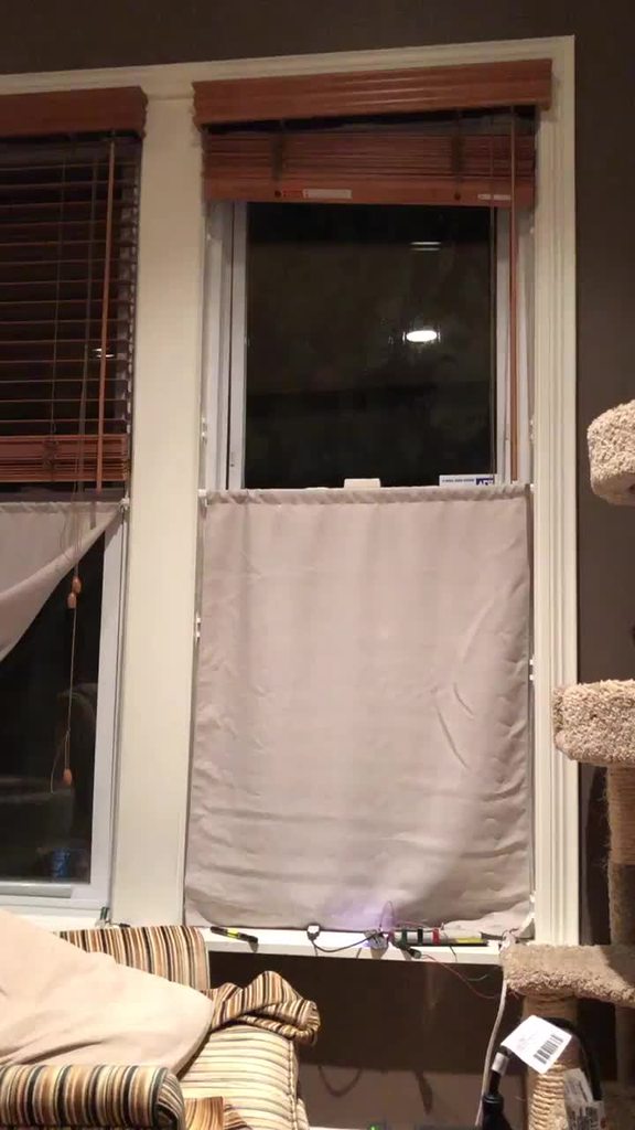
as long as I can get something orange/purple for Halloween, that's my only short term goal 😁
 tawny creek
random question: if a board is set up to be an express board with spi flash, what happens if I remove the flash chip? would it run like a non-express board?
thinking of building a custom pcb to fit inside a gba case and storing the spi flash on cartridges like 'programs' + some i2c sensor or some other peripheral -- but if there is nothing inserted it would run off the chip like a non-express board
hmm or maybe store a micro sd inside the cart instead and retain the spi flash
 wind trellis
@tawny creek It's all about the CircuitPython build that's on the MCU chip, right? If you put a uf2 on it that's for a non-Express board, the whole file system will be on its own flash and it won't look for an external spi memory chip.
Micro sd cards are ginormous compared to the size of the spi flash chips being used. Getting CircuitPython to use it the way you want is "a simple matter of software," as the saying goes.
main meteor
I chatted with the folks about using the faster QSPI interface built into some of the fancier chips and using the SD card as extended flash. LadyAda said I was welcome to try it, but her (well informed) feeling was that SD cards weren't fast enough to make QSPI much of an advantage. That said, I agree that modifying the code to use SD cards as extended filesystem storage shouldn't be too much of a chore.
 ionic elk
@indigo wedge @tulip sleet I haven't done a lot of poking into the bootloader options quite yet. Right now I use texane/stlink. I'd like to get both bootloaders as options if possible.
tawny creek
@wind trellis @main meteor thanks! I saw this:
https://learn.adafruit.com/micropython-hardware-sd-cards/code-storage-on-sd-card
😌 just thinking out loud, thanks for the insights!

Adafruit Learning System
Learn how to use a microSD card to store code & data with CircuitPython and MicroPython!
manic glacierBOT

 graceful heart
are there some certain limitations on regex patterns in circuit python? I'm getting 'ValueError: Error in regex' during re.compile for a pattern that I'm confident is valid. I'm trying to use named groups syntax. example pattern: re.compile("<(?P<var>[a-zA-Z]*)>")
looks like using groups but not giving them a symbolic name seems to compile fine
dir(matchObject)shows there is no groupDict method, so i'm guessing its only named groups that are not supported
idle owl
<@&356864093652516868> Here is the notes document for Monday’s CircuitPython Weekly meeting. Everyone is encouraged to attend! Please add your hug reports and status updates even if you’ll be attending the meeting - it’s super helpful! If you are unable to attend but would still like to include updates, feel free to include them in the notes and I’ll read them off during the meeting. Hope to see you there! https://docs.google.com/document/d/1thNdgw265YEnGSpFvKd28QU8PXJ2ccZXklYY2Y_KMwQ/edit

Google Docs
CircuitPython Weekly for 28 October 2019 Welcome to the CircuitPython Weekly meeting notes! Feel free to add your Hug Reports and Status Updates early. During the meeting, we go through them as a round robin sorted by username. If you can’t make the meeting and would stil...
onyx hinge
@idle owl I'm unlikely to attend tomorrow, and no CP activity to report. my house is all in disarray because new carpeting is being installed in the primary floor monday and tuesday. hug reports to everyone, especially those filing and reviewing PRs!
idle owl
@onyx hinge Thanks for letting me know. Please add your hug report to the notes!
manic glacierBOT
The non-recursion fix makes sense to me. The HW SPI limitation might be worth filing as an issue but the case for using bitbang seems pretty strong too.
I did not do any testing.
cdeb085 Initial Itsy nRF52840 defn - dhalbert
7d04d91 use bitbang SPI for DotStar; still need to fix ... - dhalbert
ab6fd34 add object types to rgb status objects;mark spi... - dhalbert
d0044c7 bitbangio.SPI was not setting direction of outp... - dhalbert
1103490 Merge pull request #2244 from dhalbert/itsybits... - jepler
tulip sleet
@graceful heart named groups are not implemented. We are just using the ure module from MicroPython. See http://docs.micropython.org/en/latest/library/ure.html and check the NOT SUPPORTED section.
graceful heart
Thanks @tulip sleet
Was able to use regular groups as a work around
Any plans to implement full match in addition to just match though? :) I might be able to put in some hacks to do my own pseudo full match if it's not possible.
 ruby oyster
I'm looking for the source to the Monster M4SK bootloader (UF2). I know this isn't the right channel for that, but since CP uses the same bootloader, can somebody point me in the right direction?
onyx hinge
@ruby oyster looks like it should have been at https://github.com/adafruit/uf2-samdx1 as other m4 boards are there
GitHub
MSC bootloader (based on UF2) for SAMD21. Contribute to adafruit/uf2-samdx1 development by creating an account on GitHub.
ruby oyster
The bootloader identifies itself as built for the Hallowing M4. I found https://github.com/adafruit/uf2-samdx1, but it doesn't have the Hallowing M4 board. The version number also says that it was from a fork off of 1.23.1. (The top of that repo is from 3.7.0.)
@onyx hinge Thanks for the link! It took me hours to find that originally; I should have asked here first!
I've got some bug fixes for it. The bugs exist in Microsoft's version too, so I'm not sure where to send the PR.
onyx hinge
@ruby oyster are the bugs specific to the m4sk?
ruby oyster
No; I have the same bugs on the Feather M0 Express, ItsyBitsy M4 Express, and Feather M4 Express. I have one of the bugs (but not the other) on the Trinket M0.
onyx hinge
okay, I think you should submit a pr against that adafruit repo. thanks!
ruby oyster
Gotcha. Thank you!
onyx hinge
@tulip sleet might be able to help with getting the m4sk stuff into the repo, or at least know who to ask
ruby oyster
Great, thanks! Is he usually hanging out on weekends?
onyx hinge
I hoped he would be here now, since he's showing green
ruby oyster
looks for the spell components for "Summon @tulip sleet "
tulip sleet
I'm in #help-with-circuitpython right now
ruby oyster
The README for that bootloader suggests that there isn't a lot of board-specific code, so maybe I'll just do a generic build to get my M4SK working for the time being.
Ok, thanks. I'll wait for that to slow down and then pester you there.
onyx hinge
yes I think that's pretty true
the exact vid/pid and strings may vary or maybe the status LED won't work quite right, that kind of thing.
ruby oyster
Yeah. I can set the VID/PID myself, and the LED isn't a big deal. I just wanted to make sure that there weren't things like the flash SPI being on a different pin or something.
tulip sleet
@ruby oyster you can submit issues or a PR to our repo; we try to keep in sync with microsoft. If they're very general, you can submit to the MS repo; if they're board-specific, better to submit to us. I have privs on both repos.
ruby oyster
They're very general: a USB signature is sent in big-endian that should be little-endian, and two numbers in the filesystem don't match that should. Most OSs don't check those fields, apparently, but FreeBSD does.
tulip sleet
i'd submit those to the microsoft repo
ruby oyster
Makes sense; thanks.
But first I need to build the M4sk bootloader to test them (and get my M4sk working).
I can't find the M4sk board file in the github repo, though. Do you know if that's made it there?
tulip sleet
it looks like it hasn't made it there yet, it's here: https://github.com/ladyada/uf2-samd21/tree/master/boards/hallowing_mask
ruby oyster
Awesome; thanks!
Yup, that's exactly what I needed. I'll send a PR to the Microsoft repo soon!
manic glacierBOT
This PR implements the PWMOut module on all STM32 boards. Tested features include variable frequencies, variable pulse width, and conditional rejection of new PWMOuts based on timer group and frequency.
manic glacierBOT
 graceful heart
@stuck elbow facepalm , thanks, I knew there had to be a way to do this in just regex, but wasn't sure what it was. Looking through the v3 pydocs I saw a full match method and was thinking that was what I needed. Wonder what the difference is (if any) from just adding those characters.
 trim elm
Is anyone a mod on r/adafruit? We should probably link to the discord there since it's much more active than the subreddit for getting questions answered
stuck elbow
@graceful heart I think there isn't any, it's just a convenience
manic glacierBOT
 manic glacierBOT
CI is complaining about some kind of... Itsy Bitsy issue?
manic glacierBOT
This is a version skew issue that the itsy 840 PR got caught in. I've submitted a fix PR, and can have you review it. Then you can merge from master and that should fix it. I'll start reviewing this today
@dhalbert great thanks Dan. I'll keep an eye out for your PR.
The ItsyBitsy nRF52840 board def used an older style, where MICROPY_PY_SYS_PLATFORM was defined mpconfigboard.h. It should be in mpconfigport.h. This fixes the Itsy 840 board def and also canonicalizes the SPRESENSE port.
ionic elk
@tulip sleet I'm still noticing that the version of the tinyusb submodule that git stores isn't properly updated when merging. Not just an update issue, it's the actual stored version - like it's favoring the older submodule version over the one from upstream/master for some reason. I always have to manually go in and checkout the commit manually and then commit the change.
Do you have any ideas why that might be?
tulip sleet
@ionic elk have you merged your branch from upstream, and then fixed it? Doing it once should be enough.
gilded cradle
idle owl
<@&356864093652516868> Meeting in ~5 minutes. Please add your hug reports and status updates to the docs if you haven't already. Thanks! https://docs.google.com/document/d/1thNdgw265YEnGSpFvKd28QU8PXJ2ccZXklYY2Y_KMwQ/edit
Google Docs
CircuitPython Weekly for 28 October 2019 Welcome to the CircuitPython Weekly meeting notes! Feel free to add your Hug Reports and Status Updates early. During the meeting, we go through them as a round robin sorted by username. If you can’t make the meeting and would stil...
ionic elk
@tulip sleet It's not a tough fix, for sure. But it seems to be "delayed" quite often when I merge, and since there's usually no message or anything to actually let me know it's behind before I upload to git, it's really starting to get on my nerves.
gilded cradle
Also, if you're lurking, please let us know.
tidal kiln
** lurking **
trim elm
I won’t be able to attend this week
 plucky flint
@idle owl can't make it this week (and apologies for missing last week). Family stuff going on.
idle owl
@plucky flint No worries! Life happens 🙂
pastel panther
@trim elm no worries, you can still add any hug reports or status updates to the notes if you wish/have time
plucky flint
Yeah... three of 'em. Need taking to a climbing wall somewhere. 😉
 turbid radish
Welcome Nicholas
CircuitPythin info on Reddit https://www.reddit.com/r/circuitpython/

reddit
CircuitPython - Python on microcontrollers! Welcome to our community! All things Python, CircuitPython, MicroPython and more!
 sterile bronze
lurking
turbid radish
Awesome CircuitPython List - all the CircuitPython resources https://github.com/adafruit/awesome-circuitpython
GitHub
A curated list of awesome CircuitPython guides, videos, libraries, frameworks, software and resources. - adafruit/awesome-circuitpython
I'll be not lurking I believe for this session
The Python on Microcontrolelrs Newsletter, every week on Tuesdays, all the info at https://blog.adafruit.com/2019/10/28/the-python-on-microcontrollers-newsletter-subscribe-now-circuitpython-python-circuitpython-micropython-thepsf-adafruit-2/

Adafruit Industries - Makers, hackers, artists, designers and engineers!
The Python on Microcontrollers newsletter – your #1 source for Python information every week Subscribe now, arrives in your inbox every Tuesday The word is out that our newsletter is the place for …
seems my mic isn't playing
gilded cradle
Ok @turbid radish , I can put you as text only
ivory yew
🤞
turbid radish
Ok, thanks Melissa, will need more debug time
timber mango
lurking today
stuck elbow
lurking
 river quest
CircuitPython snakes its way to the Sony Spresense
https://circuitpython.org/board/spresense/
The Spresense project consists of a Arduino compatible board with Sony’s high performance CXD5602 micro-controller. The CXD5602 has built-in GPS and high-res...
CircuitPython snakes its way to the Arduino Nano 33 BLE Sense
https://circuitpython.org/board/arduino_nano_33_ble/
This compact and reliable NANO board is built around the NINA B306 module, based on Nordic nRF 52840 and containing a powerful Cortex M4F. Its architecture, ...
ALL MONTH LONG
https://blog.adafruit.com/?s=%23OHM2019
CircuitPython powered ElectronicCats
https://blog.adafruit.com/2019/10/25/electronic-cats-open-hardware-made-in-mxico-ohm2019-oshwa-ohsummit-opensource-opensourcehardware-opensourceorg-adafruit-electronicats/

Adafruit Industries - Makers, hackers, artists, designers and engineers!
All month long we’ve looked at some of the history of open-source hardware and many of the companies/people that have helped get us all here. Today is about the future! One of the more recent…
CircuitPython snakes its way to the SparkFun Qwiic Micro – SAMD21 Development Board
https://learn.sparkfun.com/tutorials/sparkfun-qwiic-micro-samd21e-hookup-guide#circuitpython
Issue 24 – HackSpace magazine: LED matrix modules CircuitPython
https://hackspace.raspberrypi.org/issues/24/pdf

Hashtag CircuitPython life
"...finally playing with @indigo wedge's Serpente and CircuitPython, and it is crazy slick for prototyping. It's essentially what I actually want from Arduino."
https://twitter.com/arturo182/status/1188580533577670656

Hashtag @CircuitPython life https://t.co/EkkFTC1rGF
 Twitter
"CIRCUITPYTHON IN HIGH SCHOOL: AN ALTERNATIVE TO ARDUINO"
http://www.pedagogie.ac-aix-marseille.fr/jcms/c_10714440/fr/circuitpython-au-lycee-une-alternative-a-arduino-qui-se-programme-avec-python
https://twitter.com/ctrabado1/status/1188487078885105666
Cet article présente un ensemble de matériel et logiciel proposant une alternative à l'utilisation d'Arduino au lycée. Ses points forts sont : une programmation native en python, une indépendance totale possible de l'ordinateur et une vraie sortie analogique pour la gén...

Circuit Python au lycée
➡https://t.co/X5SUJNpKnn
Une alternative à arduino qui se programme avec python.
Via @Ph_Ch_Aix_Mrs
#physique_chimie #Lycée2019 #nouveauxprogrammes #programmation #codage #Python #NumériqueEducatif
 Twitter
Buy One Give One is back at 11am ET with Digi-Key, Adafruit, for Black Girls CODE
https://www.adafruit.com/product/2599

Circuit Playground Express is the next step towards a perfect introduction to electronics and programming. We've taken the original Circuit Playground Classic and made it even better! ...
In DRAFT now, ships 11am ET on Tues!
https://github.com/adafruit/circuitpython-weekly-newsletter/blob/gh-pages/_drafts/2019-10-29-draft.md
GitHub
Community newsletter for python on microcontrollers - adafruit/circuitpython-weekly-newsletter
manic glacierBOT
EIther is fine, because it's fixed by the hardware. But if you can think of a future case where mcu_tim_pin_list is not all the timers, then the current code makes more sense.
RCC->CFGR is a three-bit field, so do you need to figure out what the source multipler should be (It could be other than *2 ?
Looks good, including the timer/channel finding. It's not clear to me the prescaler/divisor choices attain the finest possible granularity. Is that true? Could you add a comment about that.
Could you open an issue on this? Agreed, it seems odd it doesn't do the opposite of never_reset_pin_number().
indigo wedge
I feel mentioned 😄
turbid radish
You have been very mentioned today
indigo wedge
Guess I'll have to watch the recording 🙂
turbid radish
Do, PT talked about you at the start
ivory yew
✨
pastel panther
theacodes -> @ivory yew 😉
ivory yew
Ah yes I realize that might be confusing. I have many names.
pastel panther
FCC ID
FCC ID application submitted by International Toy, Inc. for DS19 R2-D2 FEAT ACTION FIG for FCC ID 2AIRRINT118 ( 2AIRR INT118 ) User Manual, Frequency, Reports, Images and more.
ivory yew
🙌
ivory yew
Heck yes lasers
ivory yew
We were so close.
ionic elk
lol
stuck elbow
we need to restart @idle owl ;-)
manic glacierBOT
A cumulative counter is another approach here and that wouldn't require a clear method.
Can you expand on this a little? I'd like to get a better idea of what this would look like from the library's perspective.
We could have a way to clear the overflow flag without resetting the buffer, but from experience that means that the overflow state is likely to re-occur quickly.
Thanks for the doc clarifications! All set.
ivory yew
Thanks, @tulip sleet. That's my first two PRs to CircuitPython.  I'm 2legit now!
stuck elbow
@ivory yew congratulations!
lone sandalBOT
ionic elk
@tulip sleet style question regarding STM32 PRs - I've been leaving some commented debug statements in there, since I like to assume the worst in terms of testing and want to have them available for debugging if I need to return to the code. Would you prefer that I always clean them out before submitting a PR, and then just revert if I need to revisit things?
tulip sleet
I think it's fine to leave in a few commented-out debugging print statements, instead of having to reconstruct them or find them in an old commit. I've done that in the BLE code. Just mark them as "//for debugging" or whatever.
i only marked them because you said you were going to remoev them
ionic elk
Ok, I only marked them so you wouldn't feel you had to mark them! haha
I'll label as debugging next time.
tulip sleet
np
manic glacierBOT

And if there's a function to clear the buffer, it would be helpful to have an option clear all up to the latest full message packet to keep things synchronized.
That's an interesting idea. Currently, usb_midi is functionality just a serial port, it doesn't know anything about the actual data coming in. We could make it clear up until the next status byte without needing it to know too much about the MIDI protocol.
Exactly. Normally, I'd be nervous dropping messages, but given the alternative... Could also issue a MIDI reset message just before resuming, I suppose.
That's why it's critical to have the application know about this state and determine what to do about it. In my examples above, I used stop_all_notes as an example of one way of the application dealing with this.
I've noticed that resetting notes or issuing any other new overriding message when the buffer fills during a multi-byte message can be problematic, as well.
The prescaler value for the APB bus can only be 1 or two at this junction. This function is directly from micropython, too (do we have a standard for noting that, by the way? I've only ripped helper functions here and once in the flash library)
Yes, I'll make one now
Many modules have a never_reset function, but some such as PWMOut also include a reset_ok counterpart, which releases a peripheral from their static never_reset array and makes it available for normal use again. However, there is currently no counterpart for taking pins out of the never_reset array in any port. This means that in virtually every case, a reset_ok peripheral will still remain unavailable for use after reset, unless the user or library manually goes in and force resets e...
I don't understand how that message would help the user. If they receive this bug, they need to change their pin to a channel on a separate timer, or halt the existing PWM using that timer. Saying that no timers or channels are left for Var Freq misidentifies the problem.
onyx hinge
Hi all, sorry I missed the meeting. My news that I didn't put in the meeting notes is that I gave notice at my current job last Friday. I am expecting the next 2 weeks to be pretty nuts, but now that my colleagues know my plans I am getting a lot of support from them and a couple know enough to be in awe of what I am going to be working on now, which is CircuitPython! This transitional time is tough, but the end (beginning) is in sight. Starting mid November I'll be doing an average of 20 hours a week. Thanks to everyone here who has encouraged me. (and forgive me for making this post as a drive-by, I have to get back to work for now)
manic glacierBOT
Currently, I don't fully support the entire pin set for really big microcontroller packages. This is a cleanup issue that needs to be addressed alongside package management, since the STM32 has such a huge variety of packages. I noticed too late that I overshot my existing definitions but I'm leaving them in to be included as part of that cleanup.
I'll make a note of it in the file.
No issues with this message, makes sense.
I also feel this would misidentify the error in a confusing way. More channels are available, and they could use them, if they match the frequency. I'm not sure how it would steer them to avoid the problem. Could we go with "You must match the frequency of the existing PWM on this timer"?
This also seems misleading to me. "Cannot vary frequency on an in-use timer" perhaps?
I'd suggest "Cannot vary frequency on an in-use timer"?
manic glacierBOT
Do you mean that clk_div is only 0 or 1, and won't be 2 through 7? That's what I was wondering about.
No reason to note taking from MicroPython if the code is straightforward.
I see what you are saying. That seems OK. In the other error messages I would say "timer channel", because just "channel" may not mean a lot to the user.
"Frequency must be the same as as the existing PWMOut using this timer".
Maybe "Cannot vary frequency on timer already in use".
manic glacierBOT
Some chips have SPI peripherals that can vary in max frequency. For instance, the nRF52840 has 8MHz max normally, but has one that can do 32Mhz. Currently we have no way to specify which we would prefer at construction.
It would also be nice to specify the starting frequency in the constructor, rather than having to call configure(). The other configure()` args could also be passed in, but that's less important.
Also, I'm not sure why it's called baudrate instead of frequency for ...
ivory yew
is there a comprehensive list of build options anywhere (for mpconfigboard.h and mpconfigboard.mk)?
raven canopy
@ivory yew the most "exhaustive" i know of would be: https://github.com/adafruit/circuitpython/blob/master/py/circuitpy_mpconfig.h
for only shared-bindings options: https://github.com/adafruit/circuitpython/blob/master/py/circuitpy_mpconfig.mk
but, i think there are still a smattering of options that exist all the way down to the board level.
raven canopy
there's also this for the MicroPython specific ones.. https://github.com/adafruit/circuitpython/blob/master/py/mpconfig.h
onyx hinge
I could have sworn there was an Arduino brand board with circuit python support, but I don't see it on the website. Did I have a dream?
tulip sleet
arduino mkrzero and nano 33 BLE (both v recent)
onyx hinge
Okay, searching "Arduino" don't find them but "zero" does. Mystery solved
tulip sleet
manufacturer is not included in the search string, we could fix that if it makes sense
onyx hinge
Ooh with debugging USB port 🎅
tulip sleet
regular arduino zero was actually a really early target as well
these boards have no SPI/QSPI flash
onyx hinge
https://circuitpython.org/board/arduino_zero/ hmm it's listed though
The Arduino Zero is a simple and powerful 32-bit extension of the platform established by the UNO. The Zero board expands the family by providing increased p...
That is too bad, will sure limit the usefulness with cp
tulip sleet
yes, it's been there since the beginning. There's regular Zero and MKR Zero, different form factors
Scott used it as a debugging platform early in the port
ivory yew
So I want to enable micropython.native for my board, which means enabling MICROPY_EMIT_THUMB. Seems I get a build error around some missing QSTRs, error: 'MP_QSTR_native' undeclared. I'm not quite sure the right way to fix those.
indigo wedge
IIRC, every time you change qstrs you need to do a full rebuild
indigo wedge
but wouldn't enabling MICROPY_EMIT_THUMB add new QSTRs? hmm
ivory yew
I have no idea - I don't know how all this works lol
indigo wedge
ah, this seems to be broken
py/compile.c
779:    } else if (attr == MP_QSTR_native) {

extmod/moductypes.c
663:    { MP_ROM_QSTR(MP_QSTR_NATIVE), MP_ROM_INT(LAYOUT_NATIVE) },
the first one should be upper case too
i think that should fix it
ivory yew
maybe? Idk I'm getting different compile errors now.
indigo wedge
progress? 😅
onyx hinge
so-o in a clean repo of 2 months old master I added MICROPY_EMIT_THUMB = 1 to ports/atmel-samd/boards/feather_m0_express/mpconfigboard.mk and built and got a binary
however, ```>>> micropython.native
Traceback (most recent call last):
File "<stdin>", line 1, in <module>
AttributeError: 'module' object has no attribute 'native'
But it seems it should be .NATIVE, once you can build it
ivory yew
getting a lot of this garbage now:
../../py/emitnative.c:62:5: error: "N_X64" is not defined, evaluates to 0 [-Werror=undef]
 #if N_X64 || N_X86 || N_THUMB || N_ARM || N_XTENSA
     ^~~~~
(Gave up on enabling MICROPY_EMIT_THUMB from the board config, just editing circuitpy_mpconfig.h for now)
strict mode isn't happy with this micropython code
okay patched up that code
but sigh,
In file included from ../../py/emitnthumb.c:13:0:
../../py/emitnative.c: In function 'emit_native_end_pass':
../../py/emitnative.c:464:23: error: cast increases required alignment of target type [-Werror=cast-align]
             f, f_len, (mp_uint_t*)((byte*)f + emit->const_table_offset),
                       ^
cc1: all warnings being treated as errors
okay I give up on this for now.
onyx hinge
             type_sig |= (emit->local_vtype[i] & 0xf) << (i * 4 + 4);
         }

+#pragma GCC diagnostic push
+#pragma GCC diagnostic ignored "-Wcast-align"
         mp_emit_glue_assign_native(emit->scope->raw_code,
             emit->do_viper_types ? MP_CODE_NATIVE_VIPER : MP_CODE_NATIVE_PY,
             f, f_len, (mp_uint_t*)((byte*)f + emit->const_table_offset),
             emit->scope->num_pos_args, emit->scope->scope_flags, type_sig);
     }
+#pragma GCC diagnostic pop
 }

 STATIC bool emit_native_last_emit_was_return_value(emit_t *emit) {
``` @ivory yew"ignore this diagnostic right here only"
ivory yew
there's more fun errors after that lol
I got it to build. hrm. let's see if it works (I doubt it)
onyx hinge
it didn't here. 😦
ivory yew
it works
onyx hinge
You are running in safe mode which means something unanticipated happened.
Looks like our core CircuitPython code crashed hard. Whoops!
Please file an issue at https://github.com/adafruit/circuitpython/issues
 with the contents of your CIRCUITPY drive and this message:
Crash into the HardFault_Handler.
This stuff has changed a lot upstream
onyx hinge
oh good for you! What function did you compile?
ivory yew
just a simple 2+2
onyx hinge
ah I went all the way to ```@micropython.native
def fib_nat(x):
a, b = 0, 1
for i in range(x):
a, b = b, a+b
return a
works here
onyx hinge
you are on an m4 board? Maybe m0 doesn't work for some reason. Not sure why I'm using it, it was just handy.
ivory yew
m4 yeah
might send a PR with just this garbage for now.
Still a few outstanding questions here (like how to enable it on a board-by-board basis)
onyx hinge
just so we're on the same page, here's what I ended up with
I think I had to tangle with all the same things you mentioned, plus the board being so close to full that @micropython.native over-filled the flash
ivory yew
my changes:
Running your fib function is a little faster, yay:
Native 0.718994
Python 0.800903
this is on a Feather M4
tulip sleet
we have never tried to support this, and haven't merged from upstream in a long time. And what it's doing I think is just emitting calls to the basic VM routines, so it's saving bytecode decoding, but not a lot more
ivory yew
Yeah that seems to be the case.
that can be pretty significant in certain cases.
Gonna see if its worthwhile for some of the hot paths on my Eurorack module. If it is, I can submit patches upstream to at least make this an option for boards.
onyx hinge
<function fib at 0x20002be0> 61 0.672974
<function> 61 0.322998
I'm seeing a bit more savings than @ivory yew on my metro m4 express .. yay ?
that's calling fib(61) and fib_native(61)...
tulip sleet
YOu might consider whether writing a native C module would be a better solution in the long run. Also note that we still probably can speed things up by a factor of two or so, by optimizing when to execute background tasks
ivory yew
Long run that's probably what I'll do once I start making modules that need to process audio in realtime.
If only we had dynamic linking...
onyx hinge
I know tannewt has talked about wanting an audio synth in circuitpython, it would be awesome if your ideas would align with his on this
ivory yew
(dynamic linking is like the lost woods for engineers, best avoided)
onyx hinge
haha yeah it's firmly beyond what I can imagine doing
ivory yew
I'd love to prototype some stuff with scott on that, maybe once this project is behind me. 🙂
onyx hinge
🙂
tulip sleet
now, this is very interesting, in the long run: https://github.com/micropython/micropython/pull/5083

GitHub
This PR adds a tool elf2mpy.py and associated build scripts/headers to build .mpy files from C source code. Such .mpy files can then be dynamically imported as though they were a normal Python mod...
ivory yew
this is some arcane magic
manic glacierBOT
@hierophect lemme know when this is ready for me to try :)
ivory yew
yeah this would be rad for some of my future projects
I'd be able to write audio processing functions that are controllable from Python without sacrificing any speed.
onyx hinge
oh no, I gave away my halloween stickers before taking the "bride of frankenstein hair blinka" one for myself! I hope the kid who gets it appreciates what she has been given
ivory yew
anyway, things are plenty fast for my current projects which mostly just do some MIDI parsing and read inputs and control outputs at well below audio frequencies.
manic glacierBOT
On nrf, SPIM1/TWIM1 and SPIM2/TWIM2 are shared. They can be either SPI or I2C. Because of driver interrupt routine issues, it's difficult to allocate them dynamically.
Currently, we can't use SPIM3 on nrf, so we allocate TWIM0 as the sole I2C, and use SPIM1/TWIM1 and SPIM2/TWIM2 both for SPI.
But on the CPB board, we really need an off-board I2C, in addition to the on-board I2C for the accelerometer, so this PR will allocate TWIM0 and SPIM1/TWIM1 for I2C , and have just one SPI, on SPIM...
hearty rapids
working on a memory error on my feather M0. I have been using gc.mem_free() to see how big each import is. I am trying to get both the adafruit_neotrellis and adafruit_midi libraries and I am hoping that I am missing something to let this happen. is there a way to get the neotrellis import not use so much RAM?
main meteor
It has a pretty big footprint, but you can try importing things in a different order, that sometimes helps.
hearty rapids
i played around with that and i could sometimes tweak the final amount by a bit but it looks like I am just over the limit. I was really hoping there was a way to shrink down either of the midi or neotrellis to get them to fit. or if I just need to get a M4 board
also sorry just realized I should have posted on help-with-circuitpython
manic glacierBOT
If an nRF I2C (TWIM) peripheral is connected to pullups that are not pulled up, and then connected to an unpowered device, the peripheral can be initialized, but then operations on the bus may hang.
First noted on Arduino Nano 33 BLE. It has an on-board accelerometer. The I2C pullups and the device are both powered from other pins, so they can be shut off when not in use. If the pullups and the device are unpowered, we can still create a busio.I2C(), because it passes the tests that try ...

I've been having problems with I2S on the Feather nRF52840 Express running CircuitPython 5.0.0-alpha.4-260-g2b02750f1 (2019-10-26.)
I'm using an Adafruit I2S 3W Class D Amplifier Breakout - MAX98357A (PRODUCT ID: 3006).
I've been using the example programs and here are some issues:
- The sine waves only work well at certain frequencies. Some frequencies causes the Feather to reboot in safe mode. Other frequencies have very rough waves.
- Often after an I2S program completes without ...
The primary problem for @ladyada was that if code.py got into this state quickly, it seemed impossible to get into safe mode. Perhaps we just need an easier way to get into safe mode. Or perhaps pressing reset during certain operations might initiate automatic safe mode (e.g., set a flag before I2C operations and unset it when done; the flags indicates one should reset into safe mode and not restart).
 brisk bear
Anyone had issues with the HALLOWING firmware?
brisk bear
nvm, was trying to load the m4 firmware on the m0
manic glacierBOT
yes improved safemode would be great...
but also lets have a timeout of 1 second, that's forever in i2c bus time :)
indigo wedge
is there a recording of yesterdays weekly? 🙂
wind trellis
@indigo wedge yes https://www.youtube.com/watch?v=ZYQ3_ZHCP2M

Notes document can be found here: https://github.com/adafruit/adafruit-circuitpython-weekly-meeting/blob/master/2019/2019-10-28.md Visit the Adafruit shop on...
indigo wedge
thank you 🙂
manic glacierBOT
 manic glacierBOT
 ionic elk
@tulip sleet ohohoh that is really interesting. Can said C code utilize the APIs used by micropython? Does it still take the same amount of RAM to execute? Can it be used alongside existing python code? I have many questions.
...that of course I'm looking up myself!
manic glacierBOT
Figured it out. CubeMX restricts the available values but you're correct, it can vary significantly. However, the significance of this section is a timer quirk regarding the F405:
// Get the frequency (in Hz) of the source clock for the given timer.
// On STM32F405/407/415/417 there are 2 cases for how the clock freq is set.
// If the APB prescaler is 1, then the timer clock is equal to its respective
// APB clock.  Otherwise (APB prescaler > 1) the timer clock is twice its
// resp...This will also require changing both the NRF and atmel ports. I'll make an issue.
In most modules, value errors related to the hardware are managed by the common-hal module, so they can be made the most useful to the user. However, for the PWMOut module in particular, a set list of errors are passed back as a return enum, and then generic value errors are generated in shared-bindings. This has no difference in terms of functionality, but makes it difficult to generate useful errors for the user on different architectures. These value errors should be moved back to the PWMO...
Good idea. Do you have an example I could follow style-wise, by any chance?
From _bleio, we have many things like this, where we print out an error code that was returned from the underlying HAL. In this case, we don't have that, but, the point is just to show you how to print a numeric value. This one uses %x for hex, but decimal makes more sense here.
mp_raise_OSError_msg_varg(translate("Failed to read CCCD value, err 0x%04x"), err_code);
But I am rethinking this, and maybe the current errors are not really so obscure. I might phrase them as "...
Oh, that is really weird. Sounds like the documentation of a hardware bug :). If you could add a comment, maybe that whole comment, or just a summary, that will prevent headscratching to the next reader.
Yeah I added it back in as soon as I realized what you were asking
I'm struggling with the calculation that generates the duty cycle pulse. The integer math keeps messing up depending on what order the calculation gets done. This was a hack solution (uint16 max 65535/100%) that worked but I'm looking into alternatives.
manic glacierBOT
There are two free variables, so there are many solutions. But can you do the math in 32 bit. Suppose you chose the prescaler and counter value to be equal, by calculating the integer square root of the number you needed if there were only one 32-bit divisor. Then they would both be in 16-bit range, I think.
prime flower
@crimson ferry https://dzone.com/articles/eclipse-jtag-debugging-the-esp32-with-a-segger-j-l seems someone got a JLink going with an ESP32 running ESP-IDF

dzone.com
In this article, we learn more about how to use a SEGGER J-Link with Eclipse and OpenOCD for JTAG debugging the ESP32, looking at an example project.
ionic elk
@tulip sleet the actual problem with the particular calculation I'm doing regarding pulse width is that the fully reduced version of the equation suffers from integer overflow. The full equation for how long the pulse width needs to be is ((duty/65535)*100) * (MAXFREQ/freq) * 1/100. The reduced version is (duty*MAXFREQ)/(65535*freq). I can't use either of those though, the first because it would need a float, and the second because duty*PWM_MAX will overflow even a 32 bit integer
Right now I'm using (duty/655)*(MAX_FREQ/frequency))/100. If you see a way that could be improved, please let me know!
It'll break down as soon as duty goes below 1%, which I figured was fine?
Or I could just move to longint?
tulip sleet
@ionic elk If you use 64-bit ints, it drags in a bunch of library code to do that, and it inflates the size of the firmware. This was a big problem on M0, with limited flash size. STM32F4 would be better.
ionic elk
Since all it does is reduce rounding error, is that worth it?
tulip sleet
But I'm confused. Based on the link I put in the github conversation, the PSC and ARR values are identical in what they do, so their product is what determines the pulse length. So why not set them equal (to the square root), and then I think you won't have overflow.
they both divide down the pulse length
(PSC+1)*(ARR+1) = TIMclk/Updatefrequency
the duty cycle is then a third counter that says how long the signal should be high, right?
ionic elk
Yes. What I'm finding, though, is that the duty cycle granularity is determined by the prescaler, and not the period.
So for instance, in the current implementation where the prescaler simply caps the frequency at 6MHz, you lose all granularity of duty cycle at 2MHz or so
I still don't understand your NRF implementation because of the use of this "countertop" value.
tulip sleet
oh, bleh, I see. Did you look at the STM32Arduino implementation to see how they do it.
ionic elk
The stm32duino implementation of PWM is super choppy, unfortunately.
tulip sleet
The NRF implementation is different because the prescaler is only factors of two, so the solution is more constrained.
ionic elk
Was your code designed to have the prescaler just be in the N+1 range over the required frequency?
tulip sleet
it was picking the lowest prescaler value that would work, so I could get maximum granularity on the divisor
ionic elk
Because if we want granularity of duty cycle in the MHz range I think we'll need to multiply by like 4
Otherwise you get wonky waveforms
crimson ferry
@prime flower Good news, thanks for the link, now I need to obtain and learn how to use a debugger 😉
tulip sleet
it would be fine to compute the vlaues you need as floats an then convert back to ints
then you'd avoid all the *100 stuff
ionic elk
Won't floats bloat things too?
tulip sleet
no, we have hw floating point
ionic elk
I mean, the rounding error is sub 1%
tulip sleet
we do plenty of other computations in float
all the timer values are floats. we just have to avoid inadvertantly using double-precision float: that brings in excess libraries
prime flower
@crimson ferry yep, i havent tried it yet so YMMV. The ESP32 IDF doesnt officially support the jlink, that's why this is interesting.
ionic elk
Ok, I can swap over to that
tulip sleet
see if it helps: i think it might make things simpler. If a value is out of 16-bit range, then you can adjust the other 16-bit value by a factor of 2 at a time, say, until they both fit in 16-bit.
(maybe the latter is another way to do it without resorting to going to float and back again)
but don't worry about the cost of floating point math. This only happens on frequency set, so it's not in a tight loop or something, and the hw floating point is plenty fast
you would use the native 32-bit floats (mp_float_t) not the weird 30-bit MicroPython floats
ionic elk
The question is which do we value more - granularity of frequency selection, granularity of duty cycle, or some midpoint?
The tradeoff here is that the granularity of your duty cycle is your prescaler_freq/period_freq, which implies you want the prescaler_freq to be much higher than your user frequency, but if you want maximum granularity, you want prescaler to be as close to the user frequency as possible.
@tulip sleet
So it's a very direct exchange. Either you get more control of the duty, or more control of the frequency, but they come at the other's expense.
tulip sleet
@ionic elk In the case of a servo, the frequency is really unimportant, it's the duty cycle we care about. In the case of PWM music, the frequency accuracy is a lot more important.
Does the atml impl give any clues?
ionic elk
seems like he just goes for resolution
but it's not a smooth prescaler like I have, again
tulip sleet
yeah, I was just typing that
ionic elk
just a streight divisor
But I also don't know how atmels calculate pulse width
If I use that method, I'll end up with a divisor that's right above the user one for higher frequencies... but that'll mean those frequencies won't even work, because your duty resolution will be less than 1
I need a set duty resolution here, I think, so I can make that the multiplier of the user frequency, and then I can scale down from that.
4 bit?
tulip sleet
4 bit is pretty terrible for servo positioning reoslution
i would go for duty cycle resolution over frequency accuracy, because there are other ways for us to generate tones besides PWM
tulip sleet
but you will still divide it down??
ionic elk
What granularity do you want for PWM?
tulip sleet
16 bit is good if you can get it
ionic elk
Ok, well, I can't do 16 at all over 2MHz
16MHz post divisor gives 8 bit granularity at 2MHz
tulip sleet
so what is the count register counting up to?
see page 5 table. Are you sure that the count is not counting up to the frequency period? I know you said not, but I'm still surprised, and this chart implies that lower freq is better for resolution
is ARR = 1?
(I am not suggesting using that dithering technique; I was just looking for STM app notes.)
ionic elk
I must have miscommunicated - that app note describes our exact problem
improving the frequency resolution is at direct odds with achieving high pulse granularity at high frequencies
tulip sleet
what's the input clock value
tulip sleet
no, no dithering, no no,
ionic elk
I have this in a debugging window right now. If I use 16MHz cap (post prescaler frequency), there are 16 pulses in a period at 1MHz. EG, 8 bit
If you want 16 bit, our max frequency will be 5MHz
well, not actually because I can't divide cleanly to that
tulip sleet
so suppose we are using 50 Hz as a servo frequency, we can prescale that down to 12817.5.xxx with PRESCALE = 65535, and then divide it down still further to about 50 with ARR. Then we have an ~50 Hz period, and we have 16 bits of count to work with
ionic elk
Yeah all of this is no big deal at all at low frequencies, only high ones
tulip sleet
when you say cap, you mean highest or lowest possible?
ionic elk
5MHz is the mathematical highest we could go, because 5*16=80, and any higher will exceed the internal sysclock of 84MHz
The real cap is lower because I don't think I can hit 80
with the maths
No wait this is a 16 bit divisor of course I can
So yeah whatever your max frequency is, over 16, is the max possible frequency at which 16 bit resolution is possible'
tulip sleet
right, that's the computation in the atmel impl, which is just assuming power of 2 division, I think
is the problem that the constructor doesn't give the min and max frequency values, so you have to guess? I'd guess that the given is the highest, so get to just above that
ionic elk
My suggested solution is to take the user frequency, multiply it by 16, and find the prescaler that's just above that.
how does that sound?
Sorry I didn't mean to sound impatient there
Just trying to figure this out. Also a little disconcerted that the app note you posted doesn't seem to follow this math, so I'm trying to figure that out.
tulip sleet
why multiply by 16? that makes it 16 times coarser
ionic elk
because that's what's required to get 16 bits of pulse resolution
wait no I need to multiply it by even more
16 bit resolution is a high ask
tulip sleet
i don't get that, suppose the user gave 42 MHz as the frequency, then the prescaler divisor would be 2 to get to that exactly. Then the 100% pulse width is 1/42MHz seconds, and we divide that up into 65536 intervals
using the counter register
so 49% pulse would be .49 *65536, etc
ionic elk
Ok I just reread the appnote and it's right on, I just wasn't being harsh enough. The formula is this: Timer clock = PWM frequency x 2^PWM resolution
If you want 16 bit resolution on pulse width, as in, 65536 pulses per period, a 72MHz system clock is only going to allow 1.1Khz max PWM frequency
tulip sleet
ok, i'm confusing the required clock freq with the pwm frequency
the clock has to run faster to be able to count at a fine grained resolution
to increment the COUNT register
ionic elk
So 16 bit PWM resolution means our MAX pwm frequency would only be 1.2KHz. I imagine this is unacceptable
tulip sleet
🤦
ionic elk
yah
Here's the table:
STM32 16-bit timer PWM resolution PWM frequency
72 MHz 16 bit ~1.1 kHz
72 MHz 14 bit ~4.4 kHz
72 MHz 12 bit ~17.5 kHz
72 MHz 10 bit ~70 kHz
72 MHz 8 bit ~281 kHz
72 MHz 6 bit ~1.125 MHz
72 MHz 4 bit ~4.5 MHz
It's a decent measure since 72MHz is probably around the limit of lower speed boards anyway
tulip sleet
so did i implement nrf PWM wrong
tulip sleet
no, it's right:
// Find the smallest prescaler value that will allow the divisor to be in range.
// This allows the most accuracy.
That's favoring frequency again.
Isn't it? Or are you multiplying by a factor of pulse width accuracy?
Yeah I don't see a factor in there for anything pulse-width related
For now, could you pick a resolution/max-freq selection off the chart for me to use? I'm sorry to bug you like this, I just don't know which is a good fit for the ecosystem
ionic elk
Ok, and there's nothing PWM related that needs to go above 250kHz?
tulip sleet
not that I know of, we use PWM for IR, but that's 38 kHZ
if we were just trying to generate a particular frequency, that's kind of a different thing, but it wouldn't need to be PWM'd.
i was really keen on frequency accuracy, but I should change this
ok, thanks for talking through this, I have to think about what to fix
ionic elk
OK! I'll do a 256 multiplier off the user frequency, and then find the lowest prescaler to accomidate that
Thanks for your help Dan, I understand it better now too
And that's a good appnote to keep in mind too
tulip sleet
ok, i think we're ok, sorry for the wayward track
ionic elk
What you'd want to test for in your existing implementation is that you're getting sufficient pulse resolution when your frequency is close to a divisor value