#circuitpython-dev
1 messages · Page 179 of 1
 tulip sleet
 solar whale
@tulip sleet no problem on the servo. Glad to sacrifice one, and it still works, but I want to keep a close eye on it! so far 2300 or even 2350 seems OK, but s till need some more testing. lower limit of 600 or even 550 has not caused any problems yet. Still, I wonder if the nominal setting should be fo 90 degree range of motion at 1000 and 2000 then let the user go beyond if they want to try it.
 tidal kiln
is this for defaults? or for absolute limits?
solar whale
there are no absolute limits now, are there?
tidal kiln
there are. but it's servo dependent.
solar whale
but not in the library. the servos have physical stops, correct
tidal kiln
oh, you're talking sw. the library has no checks?
tulip sleet
the Motor library has min and max values for the pulse width. Its only way of setting the servo position is .angle, which is restricted to 0-180 (you can change the 180 but it's just used proportionally).
so .angle does restrict you to the min and max pulse widths. they were 1000-2000, but that gave a fairly small range of motion. Limor suggested in a CE mtg to increase that to 550-2400. This worked ok with my small sample of servos but was too big for one of Jerry's servos.
solar whale
but you can set the limits on the servo min_plulse/max_pulse as you want - are there absolute limits?
tulip sleet
they are not that consistent
no, the constructor doesn't restrict whta limits you can set
solar whale
it would accept 100-5000 wouldn;t i?
tulip sleet
yes, it's your job to be careful
we can document it more to be careful
someone could have some unusual servo that's really wide: I've read of 500-2500
solar whale
right - I like the flexibility it offers, Choosing defaults is really the only issue.
tidal kiln
i think it's a trade off of what will work for all servos vs. trying to get the most range
tulip sleet
yeah, we just need safer defaults
solar whale
all servos can handle 1000-2000
tidal kiln
i echo what @stuck elbow was saying yesterday - 1000-2000 and 90 deg is pretty much all there is
solar whale
it is frustrating when they only move 45 degrees if you want 180
tidal kiln
what's surprising is how far beyond that you can go with pretty much any servo
tulip sleet
i see less than 90 even with 1000-2000 on a sample micro servo
tidal kiln
yep, and 180deg total is WAY more useful than 90deg total
solar whale
the sg92r seem to go much further than the sg-5010
tulip sleet
so i think if we choose limits that are safe for what we have in the store, that would be ok, and people could adjust if they want even wider. what "safe" is requires a little testing
tidal kiln
and i'd be conservatively safe
if you're tying to dial it in to 2300 vs. 2350 level of granularity, that's a little too fine
 meager fog
lets do 750 to 2250
thats only 50% more than standard
but not beyond any limits ive seen
tulip sleet
sounds good, and I can add some doc in the libraries about this, and we can say more in the guides too, if necessary
solar whale
sounds reasonable.
I have a few different servos to test - I'll see how they respond to those limits.
tulip sleet
SG-5010 on my desk is doing 90deg at 750-2250
tidal kiln
also, my bad in a delayed project - i've got a box of stuff that will hopefully eventually become a servo characterizer rig. it'll be a jig that will come up with tables of timing vs. angle for any servo you throw in it.
that info would totally answer these questions
 prime flower
that. that is cool
solar whale
@tulip sleet do you have an SG52r -- I'll bet it goes much further on same inputs
tidal kiln
not only limits, but how non-linear it is beyond 1000-2000
tulip sleet
SG92r (micro) is about 140 degrees with 750-2250, but i have one more of each I will try
solar whale
that is consistent with my observations
tulip sleet
i only have one sg5010, i don't have an sg52r
solar whale
I meany 92r sorry
tulip sleet
oh wait another sg5010 on my desk
solar whale
I also have a 90s to try
I think the sg-5010s are a bit weird.... had some very odd beavior on one for awhile, but now it is OK -it was stuttering and not moving properly for several seconds, then seemed to recover ...
tulip sleet
I have four going at once: all are about 135 at 750-2250.
tulip sleet
two sg92r, two 5010
so I think limor is right, that's safe, and it's not a lot less than the 170 or 180 max, which is good. It's a lot better than 1000-2000
anyone who wants more can carefully tweak it up
solar whale
agreed
tidal kiln
2nd
tulip sleet
ok, thank you all! @solar whale @tidal kiln @meager fog I will file some PR's
solar whale
thank you!
tidal kiln
that answers the timing limits, but what about the (servo dependent) mapping to angle?
tulip sleet
doing some testing...
solar whale
I like that the crickit.servo has the actuation_range parameter
tulip sleet
you can specify the actual range to calibrate it:
servo1 = crickit.servo(SERVO1, min_pulse = 750, max_pulse = 2250, actuation_range=135)
that's true in the motor library, not just the crickit library
so by the above, it's actually pretty close to reality
but there's a lot of code written already that does 0 and 180, so maybe we shouldn't default that to 135, but leave at 180
solar whale
sg-5010 has notably slower speed to reach setting -- do you see that?
tulip sleet
it's probably geared lower for more torque?
tidal kiln
use whatever seems like actual average amongst the servos for that timing
tulip sleet
@tidal kiln so you're proposing 135 as the default, not 180?
if 750 and 2250 are the other defaults
tidal kiln
is that more like what they do?
tulip sleet
yes, that's true, but there are a ton of demos written already that assume 180
tidal kiln
i know 😦
but we also get a lot of forum questions that are about not getting expected range
and it's basically just servo dependent behavior /reality
under the hood, you're just doing a linear mapping?
tulip sleet
yes, it's just a scaling factor
tidal kiln
and you allow extrapolation?
tulip sleet
no, can't go past actuation_range
tidal kiln
ah
tulip sleet
ideally i guess we would have constants for each kind of servo, with some tolerances and safety margins built in
tidal kiln
yep. and the data i hope to someday generate would be what you use to feed into that.
solar whale
ah -- switched 5010 -- this one is much better behaved -- it is the one with the broken stop but it responds fater and does not get hot like thother one!
range is same as the sg92r and mg90s ~135
tulip sleet
@tidal kiln so when you finish the data collection, we can add some more library stuff, but for now, what should we do? Do you want to ping Limor about this and propose something?
solar whale
I think the slow one is drawing a lot more current - must be binding
tulip sleet
i think 750-2250 is good to save servos from breaking or drawing too much current, so the main q is whether the default angular range should be as observed or not
tidal kiln
@tulip sleet yep. i gladly defer. i really don't know best answer here. there's the issue of what the servos actually do, but also the ultimate goal of making them easy to use.
figuring out the former is a fun engineering hack project. somehow making sure we maintain the later is a matter of trade offs and design decisions.
solar whale
We know they won't go 180 so perhaps 135 will be less confusing.
tulip sleet
i can ping limor in hipchat abt it for a decision
tidal kiln
@tulip sleet totes. and sry if i'm just adding confusion.
tulip sleet
i'll ask - she's always practical about what to do. There is actually an internal ._fraction property that could be exposed.
solar whale
hmm- maybe have both. In the end, users have to realize these are not calibrated instruments and will have to tune them to their projects.
tulip sleet
I like having both
solar whale
me too.
tidal kiln
angle is more intuitive / beginner friendly
tulip sleet
hardly any new code. I just have to make it available in the crickit lib: one more property
solar whale
yes, but if the angle says 180 and it goes 135, it will be confusing -- I just think that needs to be explained in the doc. angle is very likely to be wrong.
tulip sleet
but if there's a linkage attached, fractions of movement is helpful
solar whale
servos are just not beginner friendly devices 😉
tulip sleet
I composed a query to Limor and will hit return on it if ok by you folks. covers all the above
solar whale
go for it - thanks!
I have to head out for some errands - before it gets too hot! back later.
tulip sleet
bye, thanks!
tidal kiln
sry. wondered off to forums. sure @tulip sleet . fire away.
tulip sleet
@solar whale @tidal kiln limor says keep 0-180
I'll document it in the method descriptions.
that it's wrong, expect 135, and you can adjust if you give the range yourself
solar whale
Sounds good!
 manic glacierBOT

 timber mango
@tulip sleet Not sure I have a good suggestion/path for the servo stuff, but here goes:
[15:22 UTC] Dan Halbert: i see less than 90 even with 1000-2000 on a sample micro servo <<
I was doing a project using the SeeSaw breakout .. in January, maybe.
I think it'd be worthwhile to put your Extech 330 on the servo pin and measure the signal (especially for base carrier, which iirc was about 47 Hz on SeeSaw breakout, after the patch was applied .. see below).
The SeeSaw module shipped without a 50 Hz servo frequency available -- it was much higher (270 Hz maybe; I don' t know if I documented it).
After filing an issue with Dean M I learned that the firmware had been patched and I could update it, so I ended up with a proper 50 Hz servo frequency.
In the meantime, I found that the much higher carrier (say, 270 Hz) did operate the servo, but was restricted in range (similar to your 90 degree result).
After reading what @stuck elbow said here yesterday, I'd suppose it was a 'stronger' movement (more torque) but restricted in range.
After reading what you cited (offsite doco) I'd imagine that there wasn't time between pulses (at, say, 270 Hz) to move the servo arm all the way to its destination.
(my reference servo is http://adafru.it/169 Tower Pro SG92R)
tulip sleet
yes, we made the default 50Hz everywhere, but the restricted range is due more to the pulse width than the frequency, I believe.
timber mango
The Extech 330 seemed do a good job measuring the duty cycle (I have forgotten which units that was expressed in)
I just thought it was an oddball factoid you might get some insight from. I know we don't want to prescribe varying off of 50 Hz. ;)
scurries back into the woodwork
 idle owl
@strange pumice Ok. This has been reopened: https://github.com/adafruit/Adafruit_CircuitPython_MLX90614/pull/6 It failed to build, however. Take a look at the Travis log, and then I'll explain what the error is because it's one we all run into and it always takes a few times running into it before you remember to do it ahead of time. https://travis-ci.org/adafruit/Adafruit_CircuitPython_MLX90614/builds/397993259?utm_source=github_status&utm_medium=notification
 timber mango
@idle owl is your git/github masterwerk available yett?
 strange pumice
@idle owl - looking at build issue
idle owl
@timber mango Not quite. It's waiting on final approval.
timber mango
Thanks. Very interested in this!
idle owl
@strange pumice Ok, paste the error in here, I want to make sure you're seeing the right thing.
strange pumice
@idle owl
Warning, treated as error:
autodoc: failed to import module 'adafruit_mlx90614'; the following exception was raised:
No module named 'micropython'
idle owl
Excellent!
Ok. So the issue is that Sphinx can't deal with the fact that the libraries that each other lib is dependent on are not included with it. So in the conf.py file, we have to do an autodoc_mock_import for the libs used by this driver. I'm going to put in a change request with the correct line highlighted so you can find it easily on the PR.
strange pumice
great
idle owl
Ok it won't let me request changes because I already approved, but I submitted a review with an inline comment. Take a look at the PR 😃
strange pumice
ok
idle owl
Remember, all you need to do is make the changes and push them to the branch you're using, which looks like master and the PR will update automatically.
It even automatically triggers a new build each time you push, so there's nothing else you have to do there either.
strange pumice
@idle owl - no problem uncommenting the conf.py line for autodoc_mock_import. I'm a little concerned that if I just do a push at this point it might go the wrong branch.
idle owl
It looks like you pushed to the PR on master so as long as you made changes to master, and push those, it should go to the PR. Also, make sure you take out the digitalio and busio since they're simply examples and are, from what I can see, not needed for your driver.
If you push to the wrong branch, it won't mess anything up. It simply won't update the PR. For what it's worth, it wouldn't let me reopen the current PR without closing the one you had open because they're both on the same branch. So GitHub knew.
 slender iron
@solar whale if you have time mind testing this? https://forums.adafruit.com/viewtopic.php?f=60&t=137553
solar whale
sure -- should be able to try it in the next half hour.
slender iron
awesome thanks!
idle owl
@strange pumice It worked!
strange pumice
@idle owl - okay, pushed to my forked master. I did not see digitalio being used in the examples/ or guide code.
idle owl
Ok, so you uncommented it but you have to add the libraries I mentioned in the change request. and remove the current ones
so replace ["digitalio", " busio"] with ["micropython", "adafruit_bus_device"]
strange pumice
okay, modifying
 fading solstice
@idle owl i have more time for reviewing github workflow docs. need volunteers?
idle owl
@fading solstice I think it's good for now, it's had three reviews and is waiting on the final one now. Thank you so much though! I really appreciate the offer. After it's published though, I'd love it if you could go through it. I'd love any feedback.
fading solstice
k
strange pumice
@idle owl - okay...pushed
idle owl
Alright! Waiting on Travis.
@slender iron If you have a chance, can you look at the PR to verify your change request has been covered? https://github.com/adafruit/Adafruit_CircuitPython_MLX90614/pull/6
slender iron
@idle owl yup yup
idle owl
Thank you!
strange pumice
@idle owl - build fail..indent issue. fixing it now.
solar whale
@slender iron just a bit longer -- I have to put headers on esp8266 to test it -- setting up now
slender iron
no rush 😃
idle owl
@strange pumice Ok 😃 We all go through this... Travis is a fickle gatekeeper
So much so that Dyno won't even let us talk about it 😄
solar whale
oops - I was complementing Travis on its thoroughness 😉
strange pumice
@idle owl @slender iron - thank you...
strange pumice
😃
idle owl

GitHub
Contribute to Adafruit_CircuitPython_MLX90614 development by creating an account on GitHub.
strange pumice
@idle owl - Do I need to do anything else such as the binary compiled version of this? I imagine that is automatically done as part of the CP Bundle.
idle owl
Correct, that's all automatic. What we do need to do is the first release, and get it submitted to the bundle though.
Then get it hooked into Read the Docs.
manic glacierBOT

@arturo182 I'd suggest you make a new board for yours. It'll be easiest that way.
@hathach I use GDB + JLink and recommend it. (I haven't used it on nRF yet though.) To switch the serial connection to USB you'll need to change this file: https://github.com/adafruit/circuitpython/blob/master/ports/nrf/supervisor/serial.c The SAMD version is here with [a helper](https://github.com/adafruit/circuitpy...
idle owl
I do the first and third on that list. You should be able to submit it to the bundle 😃
And I need to get it into Travis.
Oh... wait
No it's in there, the issue is capitalisation on the badge in the Readme
Time for another PR! 😄
strange pumice
kattni - this line: https://github.com/adafruit/Adafruit_CircuitPython_MLX90614
GitHub
Contribute to Adafruit_CircuitPython_MLX90614 development by creating an account on GitHub.
idle owl
    :target: https://travis-ci.org/adafruit/adafruit_CircuitPython_MLX90614
    :alt: Build Status
See adafruit isn't capitalised.
So it's targeting the wrong thing and the badge is looking for the wrong thing.
in adafruit_CircuitPython_MLXetc
strange pumice
okay. I will fix.
idle owl
The first adafruit is good as is
strange pumice
yeah, I see it.
manic glacierBOT
No need to add another API. Just make mp_hal_delay_us this implementation. It shouldn't be used for >1ms timing.
 slender iron
@tulip sleet have you actually measured the pulse widths you are generating?
idle owl
@slender iron I setup RTD on it but RTD says the build is failing. I'm pretty sure I did everything right. But obviously something isn't right.
slender iron
@idle owl did you find the build output?
idle owl
I tried to but it's not loading anything. Is that where I click on "Builds" and then click on "Triggered" in the list below it in RTD?
tulip sleet
@slender iron no, but I can and will. I know you said they might be off, but didn't seem likely to be way off.
slender iron
@tulip sleet On USB probably not but off it will be
slender iron
I renamed bus device yesterday 😃

GitHub
This matches the underscore pattern in the repo name on GitHub
idle owl
Ah.
slender iron
its the "no matching distribution" line
idle owl
Ok... I thought it was failing on pip not being upgraded.
slender iron
nope, don't think so
idle owl
No you're probably right. I was confused because it put the pip suggestion after the error.
So where is it wrong?..
solar whale
the hunt is on -- where could I possibly have stashed a lis3dh sensor ...
slender iron
yes please 😃
idle owl
Done
tulip sleet
@slender iron on USB: 1000us actually 1024us, 2000us actually 2048us,
off USB SAME (I removed power and restarted up). So lookin good!
slender iron
with m0?
tulip sleet
yes, CPX
slender iron
ah, the CPX is smart and remembers it calibration
try another m0 board w/o crystal for kicks
@stuck elbow did you get an odroid-go?
idle owl
This is new. Travis errored on this after I changed the requirements.txt file: The command "cd docs && sphinx-build -E -W -b html . _build/html" exited with 0. store build cache $ rvm $(travis_internal_ruby) --fuzzy do ruby -S gem install dpl invalid option "--api_key=" failed to deploy
manic glacierBOT
#975
display a error if nothing provided.
tulip sleet
@slender iron Trinket on a wall wart, no USB: 1000us actual 1015us, 2000us actual 2031. Not bad
idle owl
And docs failed on No matching distribution found for Adafruit-Blinka (from adafruit-circuitpython-busdevice->-r requirements.txt (line 1))
slender iron
it is a package: https://pypi.org/project/Adafruit-Blinka/

PyPI
CircuitPython APIs for non-CircuitPython versions of Python such as CPython on Linux and MicroPython.
idle owl
hmm.
slender iron
its python3.5
idle owl
Ok. How does this get resolved 😃
slender iron
GitHub
Contribute to Adafruit_Blinka development by creating an account on GitHub.
i think we need to change that
(I'm not sure why its 3.6)
idle owl
I was going to say, will it still work if we change it?
slender iron
we'll find out
slender iron
I'm doing it
idle owl
ok keen
solar whale
@slender iron sorry for the delay - I am tearing apart my workspace trying to find my lis3dh sensor. if/when I find it, I'll run the test... what a mess.
idle owl
@slender iron triggered. I'll let you know when it finishes.
slender iron
@solar whale no worries! feel free to have someone else look. I don't know if I have one thats not on a CPX
@idle owl kk, thanks
 latent nimbus
Good day, I have RGB LCD Shield kit with 16x2 character display product ID714. Is there a driver in CirquitPython for this display on I2C?
tidal kiln
@slender iron @solar whale i can take a look. neopixels will be 8 strip rgbw, in case that matters.
solar whale
@tidal kiln thanks -- still searching ....
tulip sleet
@latent nimbus https://github.com/adafruit/Adafruit_CircuitPython_CharLCD and here's a guide page: https://learn.adafruit.com/character-lcds?view=all#circuitpython-code
latent nimbus
Yes I had found that, but with the shield it becomes a i2c display? There is a shield with an MCP23017 on it to drive the display
oeps @tulip sleet Yes I had found that, but with the shield it becomes a i2c display? There is a shield with an MCP23017 on it to drive the display
idle owl
@slender iron It passed, thank you!
slender iron
yay!
 stuck elbow
@slender iron got the odroid go today
slender iron
what do you think?
 stuck elbow
it's good, not too heavy, comfortable, the buttons are a bit worse than in µGame (they are exactly same as in gameboy), the sound is horrible (but I blame the emulators)
it only has 3 sound modes: mute, loud and super-loud
slender iron
I like the dpad more for diagonals
stuck elbow
it gets around the lack of usb disk by transferring files on the sd card -- but it copies them from it, so you can play without the card
didn't try to program it yet
I don't like the high-res display and blurry pixels
but I suppose this is what most people prefer
slender iron
yeah, I wish it came loaded with something
stuck elbow
I might hack the emulators to add a "1-1" mode
it comes with all the emulators
gb, gbc, nes and gamegear
tidal kiln
@solar whale having trouble using ampy, been a while since i've done this, looks like i have v1.0.3, any known issues with 3.0rc0?
ampy.pyboard.PyboardError: could not enter raw repl
solar whale
I have ampy 1.0.4
slender iron
I really like the size and case. only wish there was a headphone jack
stuck elbow
@slender iron so you got one too already?
stuck elbow
which one did you use? I initially used the one without the hole in the middle, but it was quite bad, to switched to the other one
 bronze geyser
i created a module (like the read the doc eg for micropython - mymodule). i put this function in ```
STATIC mp_obj_t mymodule_deep_sleep(void) {
printf("Hello world! \n");
SET_BIT(SCB->SCR,2);
__WFI();
return mp_const_none;
}
I didn't notice they were different 😃
stuck elbow
I think the one without the hole doesn't allow diagonals
slender iron
@bronze geyser this will print to serial mp_printf(&mp_plat_print, <normal printf>);
ah interesting
bronze geyser
oops... then I'm using an INA219 ... calling the module w/in mu, the current goes from around 12 to 8...but the dotstar light is still on ...
idle owl
@timber mango It's live: https://learn.adafruit.com/contribute-to-circuitpython-with-git-and-github

From fork to merge, this guide covers all the steps necessary for a successful Git and GitHub workflow.
bronze geyser
@slender iron yah - i left it there (printf) to make sure the code went through...
tidal kiln
do i need to source install for latest? looks like pip version is only 1.0.3?
manic glacierBOT

This fixes internal pin-ordering problems in the libs.
Updates servo default pulse width limits to 750-2250.
Exposes Servo.fraction property.
Improved documentation.
@ladyada is testing.
slender iron
@bronze geyser is the dotstar changing state? we have a 1ms interrupt from systick and usb interrupts
bronze geyser
so i think i'm getting closer to putting my itsy bitsy via circuit python into m0 deep_sleep...but i'm expecting oh - around 1mA
it seems to stay green.
slender iron
the dotstar remembers its state so it won't turn off unless you transmit something to it
solar whale
@tidal kiln I guess so - I have latest repo on my system - so I guess I did.
 ruby lake
hooray, home early
solar whale
the repo is 1.0.4
@tidal kiln it won't work with the release RC0 -- you need to build 3.x
or master
tidal kiln
oh wait. forum is using beta-1.
bronze geyser
apologize. i'm clueless. i was thinking doing the SCB->SCR | = 1<<2; /* Enable deep sleep feature */ would make everything (including the dotstar) excruciatingly tired. but...
manic glacierBOT
solar whale
yes - that should work
tidal kiln
cloned ampy repo and installed. system is still running 1.0.3 for some reason...tracing down paths....
solar whale
I was hoping to try it with master first, but I need the lis3dh --- grrr
@tidal kiln you may have to do a pip uninstall
slender iron
@bronze geyser the dotstar has its own IC so turning off the microcontroller won't change it at all
bronze geyser
@slender iron and THAT's what happens when we major in Geology...something schisty is always going on.
slender iron
supervisor.set_rgb_status_led_brightness(0) (if I remember right) will turn it off
manic glacierBOT
52a1154 fix OneWire timing and DigitalInOut.switch_to_i... - dhalbert
b4fd77b fix nrf and esp8266 builds for OneWire fix - dhalbert
2a0b857 implement mp_hal_delay_us() to not need interru... - dhalbert
7028a39 remove previously added esp8266/mphalport.{c,h} - dhalbert
7c9a0e2 remove unnecessary extern in nrf/mphalport.c - dhalbert
bronze geyser
@slender iron Thank you. Makes me realize I don't know what else I can turn off on the itsy bitsy. I will attempt to blunder around any docs / schematic. Thank you.
tidal kiln
@solar whale that worked for ampy 👍
slender iron
@bronze geyser the peripherals in the chip itself may be on as well. it depends on if their clocks are enabled
we're pretty good about only having them on as needed but we haven't verified it at all
bronze geyser
@slender iron i really appreciate the guidance. thank you.
slender iron
np, I'm happy to see you get going with it
please share the code with us when you get it going
bronze geyser
@slender iron sung to the tune of "how hard can it be?" Well...sometimes...it can be....oh...well...
slender iron
😃 you've got a good start
manic glacierBOT
hold up on this, I forgot to make releases and their tags.
bronze geyser
@slender iron i was surprised how good the micropython doc was on adding a module. talk about an exercise in copy/paste!
slender iron
😃 which doc exactly? I'm glad you got it going
manic glacierBOT
Removed incorrect arg from RawSample in AudioOut example code. Updated variable sample to dac to match earlier use in code example.
bronze geyser
slender iron
awesome! written by @stuck elbow
idle owl
Started looking at trying to get basic audio going and found errors in the code examples. PR is in.
bronze geyser
@stuck elbow @slender iron Thank you very much for the excellent doc on adding a module to micropython. More often than not I try to follow a "how to" written by a developer and the experience doesn't end well. Your doc was approachable enough such that a novice like me had no problem writing their first micropython module. (refering to: http://micropython-dev-docs.readthedocs.io/en/latest/adding-module.html)
stuck elbow
@bronze geyser unfortunately it's already outdated
bronze geyser
@stuck elbow The only confusing spots I ran into was modifying the .ld file - i.e.: seems you assume an esp8266 ... not needed for m0? and this part is not needed: "Your port has a file qstrdefsport.h. In our case add Q(hello) to the list (on a new line). " (I.e.: needed to mod this file)
@stuck elbow What I REALLY appreciated was you presenting a very simple, clear example and then following up with text that typically started with "What does this code do?" and answer the question.
stuck elbow
yeah, that was all written assuming esp8266
I was quietly hoping that the developers would help to at least keep it up to date, if not to add to it over time
but there is no desire to document anything in MicroPython
they don't even update the official docs when they change things
bronze geyser
@stuck elbow "Lazy" on documentation is more common than not. This is why I appreciate your effort - and indeed all folks at Adafruit - that much more. And I speak with my wallet. I enjoy buying from Adafruit because everything - through A LOT of hard work - is approachable.
manic glacierBOT
We want to use CircuitPython libraries on other platforms such as CPython on Raspberry Pi and MicroPython. To do so, we need to better document the dependencies and get builds auto-released to pypi where pip gets them from.
Requirements
To do this work you'll need the adafruit-travis pypi username and password. You may also need adafruit-adabots GitHub password. Please contact @tannewt or @kattni if you are interested.
Instructions
Upgrading a repo requires a number of s...
slender iron
@fading solstice want to add a check to adabot? see the issue above
bronze geyser
@stuck elbow "Back in the day" the devs would give me this weird look of disdain and robotically repeat "RTFM RTFM" yah well, the manuals weren't readable.
slender iron
🙄 
tidal kiln
@slender iron @solar whale that forum code works for me. however...
solar whale
well - thats good to hear -- I guess.
tidal kiln
i did notice something related to neopixels
i'm using a strip of 8 RGBW, so modified the code for that
but i initially left their color defines a 3 tuples
this throws no error, but doesn't output anything for the RGBW neopixels
i initially thought it wasnt' working
for example, you do this:
pixels[0] = (255,0,0)
pixels.show()
and you get a blank pixel
but do this:
pixels[0] = (255,0, 0, 0)
pixels.show()
and it works
solar whale
interesting - could it be a power issue for the poster? 16 neopixels + lis3dh?
tidal kiln
i'd ask them to clarify what type of neopixels they have and what exactly the neopixel demo code they used was
solar whale
that would be good - then see if yo can add lis3dh to it as they tried.
tidal kiln
oh. one more detail, this also works:
pixels[0] = 0xff0000
I'm really annoyed that I can't find mine.
tidal kiln
so if the demo code was using that syntax, and then they switched to tuples, AND they have RGBW or something, then they could be getting same thing i did
solar whale
thats true. At least you proved it can work so must be a configuration issue on their side. thanks for taking this on .
tidal kiln
also, they say:
But when I try to combine the two into the script below the script doesn't ever initialize.
what does that mean?
idle owl
¯_(ツ)_/¯
solar whale
exactly
Unfortunately, I have to suspend my lis3dh search and head out for awhile. In search of air-conditioning - it's hot here! Sorry I dropped the ball on this one.
tidal kiln
pfft. whatever. no worries. thanks for setting me straight with ampy.
solar whale
glad to have accomplished something useful 😉
slender iron
circuitpython builds clog the travis pipes
tidal kiln
guess i can respond to forum unless someone else wants to
solar whale
@tidal kiln probably best for you - since you can follow it up. Thanks
idle owl
Travis is all build, build, build, c i r c u i t p y t h o n ....
tidal kiln
will do
slender iron
😃
idle owl
@slender iron I'm changing the CoC to Adafruit Community Code of Conduct. Since we're generalising it. Sound good?
slender iron
yup yup
idle owl
@slender iron This is ready for a (hopefully final) look, whenever you get a chance: https://github.com/adafruit/Adafruit_Community_Code_of_Conduct/pull/3/

GitHub
This is to be the new Adafruit CircuitPython Code of Conduct. It will be displayed on Discord and apply to all CircuitPython spaces.
Please read through it and provide any suggestions you may have ...
 errant grail
A comparison of Adafruit SAMD development boards from last night's CPy presentation at our local makerspace:
bronze geyser
i think i bricked my itsy bitsy m0. I can see ItsyBoot, but can't mount circuitpy. There is a troubleshooting here: https://learn.adafruit.com/adafruit-feather-m0-express-designed-for-circuit-python-circuitpython/troubleshooting#for-the-circuit-playground-express-feather-m0-express-and-metro-m0-express ...but i can't seem to get it to work for the itsy bitsy.... any advice appreciated.

Get running faster than ever with the first Adafruit Express board
um...what i think caused the itsy bitsy to brick was my playing around with putting the m0 into deep_sleep and then doing a __WFI()....so i thought if I hit the reset all would be fine. i'm wondering if besides the flash - i need to somehow reset the CPU to get it out of deep sleep...only, it keeps sleeping...
 raven canopy
are you using a jlink, or just dropping uf2's?
bronze geyser
dropping uf2
raven canopy
i would drop a new known good one on. then try and figure out what your changes were causing (hard w/o a debugger).
it might just be a filesystem thing. have you handled all that so it doesnt get corrupted?
bronze geyser
i'm sorry don't understand what you mean "handled all that?"
raven canopy
like dismount
bronze geyser
i was trying to uf2 one of those erase binaries. There wasn't one for the itsy bitsy so i gave the circuit playground a twirl. didn't seem to work.
raven canopy
and having any USB MSC connections closed before sleeping. (sorry for the delay. cleaning pizza hands)
@tulip sleet how difficult would it be to get an Itsy Bitsy filesystem eraser.uf2?
@solar whale you out of AC too? just got mine fixed a little while ago, which i why i was absent from the heatbox (aka computer) last night.
solar whale
@raven canopy we just don’t have it. Becoming more of an issue in recent years 😟
This is New Hampshire. We don’t need AC 😉
bronze geyser
hmm.. @raven canopy thanks about going to last known good on the circuit python uf2 file. i kept copying the one that i had modified ..which had worked...obviously i screwed stuff up. i hope the pizza is most excellent.
raven canopy
Ahh. Yeah, some areas it's doable. In Florida, notsomuch. 🔥
bronze geyser
curious on jlink. i'm on a Mac ...the adafruit instructions assume Windows. (Atmel). what do folks use on the Mac?
raven canopy
@bronze geyser yw. It became my practice early on when I was firmware hacking and borked things. On Mac, GDBServer is used. Maybe OpenOCD too?
There is a guide for it. On phone right this second...give me a few.
<--Windows user. The guide is for Linux, but works on Mac too.
bronze geyser
well if it is GDBServer i think i remember jlink having a command line tool for Mac...so i might try that too.
idle owl
JLink has both GUI and command line software for Mac. I've really only used the command line software though.
raven canopy
@bronze geyser https://learn.adafruit.com/debugging-the-samd21-with-gdb
bronze geyser
@idle owl @raven canopy THANK YOU! I am off to ...well...take an aspirin actually.
idle owl
😄 Good start
raven canopy
Keep it nearby for when you start dealing with Travis... 😄
fading solstice
oops. i have a metro m0 that i put an alpha verison of circuitpython
>>>
I cannot get to METROM0BOOT. Anyone point me to the re-install boot loading pages
The double click on the reset button just restarts the CIRCUITPY drive
 cobalt sail
So um is anyone able to help me with my issue?
I hate to be a pest but kinda wanna fix this soon
raven canopy
@fading solstice you can try one of these methods. outside of those, the only other thing that may work is burning and Arduino sketch, and then reverting back to 
@cobalt sail what issue are you having with uploading firware?
@fading solstice i forgot the link... lol https://learn.adafruit.com/welcome-to-circuitpython/troubleshooting#circuitpy-drive-issues
fading solstice
@raven canopy thanks
cobalt sail
https://forums.adafruit.com/viewtopic.php?f=60&t=137561 I have it detailed in this post
What errors Im getting etc etc
fading solstice
@raven canopy i like the arduino idea
@cobalt sail what hardware are you using?
i.e., the cpu board, communication board if any
timber mango
@idle owl Thanks! I'm looking forward to studying in the Git Guide!
@tulip sleet @solar whale @tidal kiln
This is the end-product of my rework of the OP's code (on CPX rather than on HUZZAH)
for that forum inquiry (viewtopic.php?f=60&t=137553).
I think it demo's the intent of the code. Not sure. ;)
raven canopy
@cobalt sail don't take this offensively, but are you sure that the correct com port is COM3?
cobalt sail
Device manager says it is
raven canopy
ok. have you tried running esptool without the python -m? i usually run it directly from the python/Scriptsdirectory in PowerShell.
manic glacierBOT
Began looking into this. I have simple code running - I'm able to send a tone through a breadboard headphone jack from an ItsyBitsy. Will discuss Monday what the plan is for this page.
Found that the sample code in RTD for AudioOut and RawSample were incorrect - submitted a PR to fix both of these.
raven canopy
reads new Blinka pypi issue; begins internal debate on wading back into docland 😆
cobalt sail
Though to be fair powershell is more powerful
raven canopy
i never use the -m switch, so i'm not sure that running it that way restricts the access to anything. i would assume that it wouldn't, and that it would provide a verbose error to that effect. but, the world isn't perfect. 😄
fading solstice
@cobalt sail do you have rx-> tx and tx-> rx
you also need GPIO15 set to ground
i am sorry the board has a pull down resister on GPIO15, ignore that last statement
cobalt sail
Just to make sure could you tell me what colors go to what pins
I'm 99% sure I have that right
raven canopy
"Grab Your Fork" @idle owl 👍 👍 🥇 😄
cobalt sail
Copied from the Adafruit website
The red lead should be connected to 5V if you want to power via the cable, see below for details
The black lead to GND (3rd pin down)
The white lead to TXD on the Pi (4th pin down)
The green lead to RXD on the pI (5th pin down)
cobalt sail
I am trying this because its what the article on adafruit said
The white lead to TXD on the Pi (4th pin down)
The green lead to RXD on the pI (5th pin down)
Unless its outdated
fading solstice
the articale is talking about rPi
cobalt sail
Yeah but the cable colors don't change
fading solstice
as long as you have white connected to esp8266 tx you are good
cobalt sail
Ok
fading solstice
and green to esp8266 rx
raven canopy
they're (rx/tx) on the short end, near the reset and gpio0 buttons.
cobalt sail
Yeah I know
fading solstice
are you able to create programs with arduino?

Adorable bite-sized WiFi microcontroller, at a price you like!
cobalt sail
Yeah but I am kinda bad with C
fading solstice
You we able to run a blink progam?
cobalt sail
Ok having the wires white on tx and green on rx still does the same thing
I can try that
fading solstice
So are you saying you switched the wires then?
Is the board getting power. any lights at all?
fading solstice
Is power coming from the cable or something else?
cobalt sail
Cable
fading solstice
ok
Ok, follow the direction in the link a prior message and get blink to work.
Forgot to ask are you using Window 10?
solar whale
@cobalt sail Are you Getting Itinto Bootloader Mode? Hold Gpio0 Botton And Fhe Press Reset.
cobalt sail
Does it do something?
solar whale
led shpuld pulse
cobalt sail
Is there a hold length?
solar whale
hold GPIO0 button down - while holding pres and release reset - ten release GPIO0
cobalt sail
Ok, instructions online were a bit confusing
tidal kiln
@timber mango cool. i didn't really look too much into what the code was trying to do much beyond just "neopixels, read lis3dh, math, print"
solar whale
sorry - led will just be dim, not pulse.. any luck?
cobalt sail
Yeah its dim and same error
solar whale
not much more I can offer - I just wanted to make sure you were aware of the bootloader step.
cobalt sail
Yeah
timber mango
@tidal kiln I needed the practice with both CircuitPython and with git. ;) Not quite sure what the OP was after but this mod was simple enough.
It's interesting to me because I don't think I got much out of the 'coin edge roll' manipulation of LIS3DH on the CPX. Now it seems to have a purpose. ;)
(without the interpretive math in the OP's program, it was not obvious to me why that axis is there)
tulip sleet
@fading solstice if you have an old bootloader, double-click does not work well. That was fixed, and you can update the bootloader. try using arduino and compile and upload https://github.com/adafruit/uf2-samdx1/releases/download/v2.0.0-adafruit.5/update-bootloader-metro_m0-v2.0.0-adafruit.5.ino. you can leave it in CircuitPython mode, cause CPy notices the attempted arduino upload and should let it happen
@bronze geyser Try loading the 2.3.1 uf2 for CircuitPython on the board, then see if you can get into the REPL, then do the import storage;storage.erase_filesystem(). Then reload 3.0.0
cobalt sail
@fading solstice Arduino: 1.8.5 (Windows 10), Board: "Adafruit Feather HUZZAH ESP8266, 80 MHz, 4M (1M SPIFFS), v2 Lower Memory, Disabled, None, Only Sketch, 115200"
Build options changed, rebuilding all
Archiving built core (caching) in: C:\Users\user\AppData\Local\Temp\arduino_cache_470369\core\core_esp8266_esp8266_huzzah_CpuFrequency_80,FlashSize_4M1M,LwIPVariant_v2mss536,Debug_Disabled,DebugLevel_None____,FlashErase_none,UploadSpeed_115200_1abeff005d95d2187661c10f16ed63eb.a
Sketch uses 246315 bytes (23%) of program storage space. Maximum is 1044464 bytes.
Global variables use 32272 bytes (39%) of dynamic memory, leaving 49648 bytes for local variables. Maximum is 81920 bytes.
warning: espcomm_send_command: wrong direction/command: 0x00 0x08, expected 0x01 0x08
warning: espcomm_send_command: wrong direction/command: 0x00 0x08, expected 0x01 0x08
warning: espcomm_send_command: wrong direction/command: 0x00 0x08, expected 0x01 0x08
warning: espcomm_send_command: wrong direction/command: 0x00 0x08, expected 0x01 0x08
warning: espcomm_send_command: wrong direction/command: 0x00 0x08, expected 0x01 0x08
warning: espcomm_send_command: wrong direction/command: 0x00 0x08, expected 0x01 0x08
warning: espcomm_send_command: wrong direction/command: 0x00 0x08, expected 0x01 0x08
warning: espcomm_send_command: wrong direction/command: 0x00 0x08, expected 0x01 0x08
warning: espcomm_send_command: wrong direction/command: 0x00 0x08, expected 0x01 0x08
warning: espcomm_sync failed
error: espcomm_open failed
error: espcomm_upload_mem failed
error: espcomm_upload_mem failed
This report would have more information with
"Show verbose output during compilation"
option enabled in File -> Preferences.
cobalt sail
Yeah I'm starting to think I got a bum board because now the red LED is barely ever showing up when I push down gpio0
timber mango
ayer-craft.
This is a variation on a theme, tracking the CPX sense of which part of the rolling edge is most 'down' (or 'up').
This is a fun demo, and requires no new hardware (just the CPX itself).
See the forum for the original poster's code.
https://forums.adafruit.com/viewtopic.php?f=60&t=137553 << fill this in, nis
 upbeat plover
import audioio
import board
import array
import time
import math

# Generate one period of sine wav.
length = 8000 // 440
sine_wave = array.array("H", [0] * length)
for i in range(length):
    sine_wave[i] = int(math.sin(math.pi * 2 * i / 18) * (2 ** 15) + 2 ** 15)

sample = audioio.AudioOut(board.SPEAKER, sine_wave)
sample.play(loop=True)
time.sleep(1)
sample.stop()
Traceback (most recent call last):
File "main.py", line 13, in <module>
TypeError: extra positional arguments given
https://circuitpython.readthedocs.io/en/2.x/shared-bindings/audioio/AudioOut.html?highlight=audio
example not working, is there a 3.x read docs?
okay... i still get same error
Traceback (most recent call last):
File "main.py", line 14, in <module>
TypeError: extra keyword arguments given
upbeat plover
import audioio
import board
import array
import digitalio
import time
import math


# Generate one period of sine wav.
length = 8000 // 440
sine_wave = array.array("h", [0] * length)
for i in range(length):
    sine_wave[i] = int(math.sin(math.pi * 2 * i / 18) * (2 ** 15))
speaker_enable = digitalio.DigitalInOut(board.SPEAKER_ENABLE)
speaker_enable.switch_to_output(value=True)
dac = audioio.AudioOut(board.SPEAKER)
sine_wave = audioio.RawSample(sine_wave)
dac.play(sine_wave, loop=True)
time.sleep(1)
dac.stop()
only way i could get sound to work... now to see if this works with my code
solar whale
@cobalt sail I ran a google search on warning: espcomm_send_command: wrong direction/command: 0x00 0x08, expected 0x01 0x08 and found a several cases where the same issue was reported. The resolutions varied. In one case the user did not have the Ground wire connected. properly https://github.com/esp8266/Arduino/issues/347 1n another, holding the GPIO- pin continuously for the upload helped https://forums.adafruit.com/viewtopic.php?f=22&t=90309 -- just a few things to try. Of course, your mileage may vary 😉 I have used these boards a lot with the 954 cable, but I have never done it via Windows. Good luck!

GitHub
Hello everyone, I am not able to upload WiFiScan Sketch. I am on Arduino 1.6.4 Here is the error Sketch uses 231,360 bytes (44%) of program storage space. Maximum is 524,288 bytes. warning: espcomm...
fading solstice
@upbeat plover Are you using Circuitpython 3.0 or 2.x. In 3.0, you may provide a left and a right speaker channel with no sample allowed. In 2.x, a mon speaker channel and optional sample.
solar whale
@fading solstice did you recover your metro m0
fading solstice
@solar whale thanks for asking. the board finally responded to the double reset. i was clicking fast enough i guess
solar whale
good.
solar whale
@indigo wedge I am playing with my new PCA10056 DK -- I was able to load the serial bootlaoder and CP3.0 master using the BOARD=feather52840 commands. Is taht the correct way to be using this board now - or should I be using the PCA10056 BSP.. I tried, but did not get very far.
 indigo wedge
for pca10056 you should be using the pca10056 BOARD value, I've been using it with the DK, what's the problem?
solar whale
Use make V=1, make V=2 or set BUILD_VERBOSE similarly in your environment to increase build verbosity.
make: *** No rule to make target 'boot-flash'.  Stop.
shpuld I use boot-flash or jsut flash
indigo wedge
on the master branch the DK doesn't have the bootloader, so you need to do make ... sd to flash the softdevice and then make ... flash to flash CP
then you can use the jlink USB uart to get the REPL
solar whale
ok -- will try that
that works - thatnks -- I totally forgot abbout the "sd" to flash the bootloader via the Jlink.
cool! ble_scan works -- now I'll try an SDcard on it to see if it work. still not luck on the featehr52832
yu[p- sdcard works on pca10056 nor me as well -- will update Issue
manic glacierBOT

Just tried mounting an SDcard on a PCA10056DK -- works fine!
Still not working on the feather52840
Oe other test I did was to unplug the SD Card on the feather52840 -- it correctly reports No SD Card -- so the SPI interface is communicating with with the baord. As Arturo pointed out the error is at the mount point.
indigo wedge
@solar whale you meant feather52832 i think
solar whale
oops -- thanks -- will fix
indigo wedge
i'll look into the issue on a feather52832 when i get some time 😃
solar whale
thanks - no rish -- just trying to update as I play with it.
is is still necessary to do the J-Link>MSDDisable wit the new DK boards.. I did it and it did not apper to do any harm, but just curious if it is still needed.
bronze geyser
i wrote a c module that i call in circuitpython. it has a method on it that puts the m0 into deep sleep and then __WFI(). i thought if i applied 3.3v to one of the gpio pins, this would be enough to wake the m0. It is not. i'm looking for advice. i want the m0 to wake up when a gpio pin goes high. do i need to implement some stuff that uses ARM's gpio library? is there an easier way? Any pointers to good docs also appreciated.
stuck elbow
I think that you have to set up an interrupt to wake it up
meager fog
hey anyone wanna try something ridicuous?

Make hardware and interface with sensors super easy using CircuitPython
solar whale
downloading it now
indigo wedge
now we just need one API for ble for RPi and 😃
meager fog
we'll get there!
solar whale
@meager fog 😦 ```pi@gjnpi3p-1:~ $ pip install adafruit-blinka
Collecting adafruit-blinka
Could not find a version that satisfies the requirement adafruit-blinka (from versions: )
No matching distribution found for adafruit-blinka
pi@gjnpi3p-1:~ $
doe it need the update to Raspian released yesterday?
meager fog
ok i updated the command lines to use pip3 and python3
i forgot i by default change it to be 3 on my pi
solar whale
cool! ```pi@gjnpi3p-1:~/projects/blinka $ python3 blinkatest.py
Hello blinka!
Digital IO ok!
I2C ok!
SPI ok!
done!
hooking up a bme280
meager fog
yayy
solar whale
woohoo! ``` pi@gjnpi3p-1:~/projects/blinka $ python3 bme280test.py
Temperature: 30.9 C
Humidity: 54.5 %
Pressure: 1013.1 hPa
Altitude = 1.08 meters
Temperature: 30.9 C
Humidity: 54.5 %
Pressure: 1013.1 hPa
Altitude = 1.30 meters
Temperature: 30.9 C
Humidity: 54.4 %
Pressure: 1013.1 hPa
Altitude = 1.29 meters
this is very nice -- looking forward to playing with more.... thanks!
meager fog
huzzah!
digitalio and i2c work
spi is in progress and is A Little Weird on liunx
but as longas you know what to expect it'll work
solar whale
Sounds great - I have been watching the PRs fly buy and was going to jump in and try it soon. Thanks for the push. Let me know if there are particular things you want tested.
meager fog
the biggest project right now is getting stuff on pypi
theres quite a few steps
we just Have to Do it
if you have sensors you wanna try ping us and we'll try to do that one first
since theres 85
solar whale
I have been working on the rfm95 lately -- someone had ported it - needed a few tweaksx -- have it working ok and was about to start on the rfm69. Since its SPI, it may have to wait until that is stable.
meager fog
wont take long
solar whale
no real rush on anything though -- I'll watch as the PRs go in and try them out.
just tried "pibinka.py " from the repo --- works fine!!
solar whale
@meager fog Congratulations on getting this going -- I think it will be a lot of fun and get a lot of use!
bronze geyser
@stuck elbow - maybe i'm missing something, but based on Scott's comment: "Why do we need ISRs as opposed to polling? Concurrency such as ISRs is complex." (see: https://github.com/adafruit/circuitpython/issues/439). The current build of CP does not support "setting up an interrupt"? Or am I missing something? Thank you. I am obviously flailing/trying to learn.
idle owl
@bronze geyser We're all still trying to learn. You're not alone in that. 😃
bronze geyser
@idle owl I must tell you, you are an absolute joy. Thank you.
idle owl
You're welcome 😊
bronze geyser
@idle owl - btw - my daughter and i had a great time going through the circuit playground express tutorial you did.
idle owl
@bronze geyser That's great to hear! I'm glad you guys had fun.
solar whale
@meager fog FYI -- I installed the latest Raspian updates -- blinka still works 😉
meager fog
Make hardware and interface with sensors super easy using CircuitPython
digital io
example code, you'll need to update blinka, command is listed
idle owl
Nice!
solar whale
updated and still working 😉
lots more pins 😃
@meager fog how recent of a Raspian does it need -- will it work on "Jessie"?
meager fog
should work on anything
solar whale
great!
raven canopy
@bronze geyser do you have your code up on github? might be able to give some pointers...
timber mango
@meager fog
https://github.com/wa1tnr/sandboxx/blob/testing-aa/new_circuit_python_linux_RPI_installation_report_aa.txt
summary: i2c group ownership, everything else went well on a pre-established RPi that'd run SeeSaw breakout i2c peripherals in January 2018.
bronze geyser
@raven canopy i can put it there...i was thinking maybe i could use a samd21 api - like system_interrupt_enable_global() ...heck, i don't think i need an isr...so i'm hoping by doing this NVIC is happy and __WFI() is released from slumber. Does this make sense?
@raven canopy i'm looking at this doc - http://ww1.microchip.com/downloads/en/AppNotes/Atmel-42122-SAM-System-Interrupt-Driver_ApplicationNote_AT03261.pdf
solar whale
@timber mango user "pi" is a member of i2c and spi on a "stock" RPi so I did not have to add pi.. good to know if you have installed other users
timber mango
.oO(..got to find a good hydrophobia movie for this weather..)
@solar whale aha! Yeah I never use 'pi' except just to peek at it. Gave myself sudo privs the day I installed. ;)
(sudo-ism was an Ubuntu-culture thing I adopted from their practice of it)
raven canopy
@bronze geyser that app note appears tbe based on asf3. we're using asf4, so need to find the equivalent...
bronze geyser
@ooh. Thanks...back to bumbling w/ Google...
@raven canopy so i'm looking at this ASF doc: http://asf.atmel.com/docs/latest/sam0.applications.asf_programmers_manual.atsamd21/html/group__asfdoc__sam0__system__interrupt__group.html it has the same api. it is not clear what version of ASF the API docs are at? How do I tell?
raven canopy
as far as i can tell, the only way to read ASF4 "online" is to create a project in Atmel START, and read the modules there. I myself just use the circuitpython repo to read/research it. https://github.com/adafruit/asf4/tree/88a67f9c83eeb225fe65f596078f8aaa3f6de1ec
@bronze geyser ASF4 was a total redesign from ASF3...
timber mango
@solar whale
 $ cat /etc/debian_version
9.3
<< my RPi
raven canopy
the premise was "load the modules you need, and don't waste time writing drivers". at least, that's what i remember... 😄
raven canopy
@bronze geyser which sleep mode are you using, IDLE or STANDBY?
bronze geyser
@raven canopy standby.
raven canopy
what clocks did you leave on?
bronze geyser
i didn't touch any of the clocks. my goal was just to get the code to continue to run on an interrupt.
raven canopy
actually, nvm. standby turns off the APB clock. Did you try IDLE?
bronze geyser
i can try idle. i'm trying to use solar on my outdoor stuff...i use standby in my Arduino code.... my current thinking is set bit 2 of SCR to 1 (standby)....tell nvic to enable all interrupts. Then when a HIGH comes in on an interrupt, code continues.
i don't need to much around with an ISR.
raven canopy
yeah, idle should be what you want then. you'll need the APB clock running for the External Interrupt Controller to generate the interrupt from a pin. at least, that is how i would approach it. there may be a better way.
bronze geyser
given that i get "implicit declaration of function 'system_interrupt_enable_global'" I guess the ASF4 goo in circuit python didn't include this jewl of code.
raven canopy
i looked in the HRI files that i would think those functions would be in. didn't see them.
bronze geyser
i do not understand why the mode can't be standby. this works on arduino?
raven canopy
or equivalents...
idle owl
I assume because we didn't implement whatever is necessary for standby to work. To be clear though, I am coming from the fact that there are a lot of things we haven't implemented, not from any understanding of what you're talking about.
bronze geyser
e.g.: i have a motion detector in my mailbox. When Randy (our mail person) opens the mailbox, the interrupt wakes up the Feather RFM69 which sends a packet to my handy-dandy-we-got-mail thingy.
i used standby for that?
idle owl
I know we don't have interrupts. Not really anyway.
bronze geyser
@idle owl yah - i just thought it might be "fun" to try to get this to work....if not, i can't use circuit python in my yard....although perhaps if i get more precise on the solar power budget.
idle owl
@bronze geyser If it's included in MicroPython, then it's possible to use with CircuitPython, as far as I understand it. There's simply a lot of it that isn't a high priority for us to work on. If someone else implemented it in a way that worked with what we're doing, we'd include it, but we have different priorities.
raven canopy
sleep modes are different among chipsets. this is what i'm basing IDLE vs STANDBY of:
idle owl
Interesting.
bronze geyser
@idle owl totally understand.
timber mango
ideas sourced from MartinL on forum.arduino.cc
http://forum.arduino.cc/index.php?topic=332275.17 ]
This uses interrupts:
https://github.com/wa1tnr/m0_timer_standalone
raven canopy
The NVIC will need the EIC peripheral to generate the interrupt to wakeup, and the EIC needs the APB clock to be enabled. again, there may be another way to do it?
idle owl
A mate of mine wanted interrupts and was prepared to start working on them, but got burned out from work and hasn't touched any of this stuff outside of work in ages. He thought it was doable though, is my point.
raven canopy
they are doable. i think it is a matter of prioritizing them in the VM loop; or rather having a construction that allows the VM loop to be interrupted at any point (or in a relatively real-time manner).
however, there are much smarter heads in this room than I, so they could answer that better. 😄
breaking the loop is probably the easy part. its starting back at the same position that is difficult.
timber mango
Well you have a state machine and just start it again. ;)
(make it async tolerant)
(not my fault if the machine paints a double moustache on the mona lisa as a result of that approach) hehe
bronze geyser
@raven canopy re: table...i remember that from somewhere. i'm using the advice from these sites: https://www.embedded.com/print/4230085 and http://virgilmachine.blogspot.com/2016/10/interrupts-power-saving-zero-oled.html here they discuss deep sleep or idle

This is a story about bumbling into moderate success. The project objective, which I met, was to build a compass. Sounds simple, but the ...
meager fog
@timber mango back, ok you tried it with seesaw? it OUGHT to work
but i havent tried that yet. starting with basic sensors
@solar whale i think we just have to figure out how to get your jessie pi set up with latest python
are you dead set against stretch?
cause pi foundation is not really a supporter or old distros
once they update they really mean it 😃
solar whale
@meager fog just did -- posting fix to issue -- no - I am slowly updating all to stretch.
meager fog
ok cool i can add yer fix to the guide
raven canopy
@bronze geyser reading that second link, and looking a little more at the datasheet, STANDBY should work if you make sure that the EIC is setup with ONDEMAND=0 && RUNDSTDBY=1. that will keep the appropriate clock running (this was buried in a note), and will allow the interrupt to occur.
bronze geyser
@raven canopy Thanks. I'll try to figure this out more after i walk the dogs. i very much appreciate your help.
raven canopy
you're welcome. sleep is on the wish list for folks, so i'm glad to help.
solar whale
yay - on the "jessie" box ```pi@gjnpi0-1:~/projects/blinka $ python3 blinkatest.py
Hello blinka!
Digital IO ok!
I2C ok!
SPI ok!
done!
yay
solar whale
probably should recommend "stretch"
meager fog
ok added a warning that you need latest
releasing another bump with SPI
only hardware SPI for now
solar whale
@meager fog Just to be clear, I did not need to update the setuptools on stretch -- only jessie
meager fog
thats right, stretch is new enough it comes with latest
never hurts to do it
there'll be new OS's 😃
solar whale
still not sure why I needed sudo for the pip3 install adafruit-blinka on the jessie system, but not sudo on stretch.
meager fog
(shrug)
timber mango
@meager fog I used SeeSaw breakout on this RPi a while ago (to operate a servo). Not recently though.
Point was that the system already had a lot of software on it to do that (in cpython).
... I remember when I used to remember ..
solar whale
@meager fog Is it necessary to do the spi.open() and spi.close() one each read/write with spidev? I ran into some issues with this and was wondering if it was really bad to just leave it open and close it when you are done.
meager fog
you do
because of the terrible terrible way SPI works on linux
we have to share the SPI device on all instances, and linux only knows about 'transactional' SPI
to keep from getting confused, we open/close the devices on each transacion. this is the Right way to do it. and linux is fast, its not going to make a huge difference
there's no way to just write data to SPI without a transaction
solar whale
OK - thanks for clarifying that - I need to go back to work on my rfm95x driver 😉 -- better wait for the CP driver...;-) but it was having issues that seemed to be related to open/close -- I'll work on it...
meager fog
honestly, in an OS i think thats wisest
otherwise different processes could inject SPI data while you're doing an xfer
solar whale
it makes sense -- seems the "polite" thing to do.
meager fog
this way the SPI is owned by you and only you, for the duration of the transaction
upbeat plover
can someone point me to a tut on how to make my own circuitpython modules? want some stuff converted to those [] and @#%#@$ what not...
.mpy
meager fog
the code or the mpy part?
https://learn.adafruit.com/porting-an-arduino-library-to-circuitpython-vl6180x-distance-sensor covers the whole process

Learn about porting an Arduino library to CircuitPython with the VL6180X distance sensor.
raven canopy
depends on the version of CircuitPython. match the major version (2.x, 3.x)
i.e. When using CircuitPython 2.3.1, any 2.x mpy-cross will work.
cobalt sail
@solar whale Sadly no dice, guess I'll just not have wifi or circuitpython since I dont have another board right now that includes it
raven canopy
@upbeat plover then you'll need a 3.x version of mpy-cross.
solar whale
@cobalt sail odd -- wish I could help
raven canopy
@upbeat plover what OS are you on?
upbeat plover
windows 10 ={
raven canopy
https://github.com/adafruit/circuitpython/releases/download/3.0.0-alpha.6/mpy-cross-3.0-windows.exe
no frowny face! i'm on Win10 too. hehe.
cobalt sail
@solar whale Its fine, you tried
raven canopy
@bronze geyser yeah. like i said, my approach would be to setup an external interrupt with the EIC on your desired pin, and make sure the EIC is setup to remain on during STANDBY. you can look at ports/atmel-samd/common-hal/pulseio/PulseIn.c for how to setup the external interrupt. you'll need to add the ability to handle the interrupt during sleep in ports/atmel-samd/peripherals/samd/external_interrupts.c.
bronze geyser
@raven canopy thank you. that helps.
raven canopy
i'm am still curious how the USB and file system are going to feel about sleep. just turning the clocks off and on may not be enough.
and, i'm off for adulting time. 😦
solar whale
@meager fog tried bme280 via spi on blinka -- no erros, but the data values are way off. - Did you get good readings?
@meager fog they are getting better with time -- it's very hot and humid -- sensor may be tired...
solar whale
too hot in 😦
timber mango
@solar whale if you get a chance, I'd like to know if the Feather M0 Express is really asleep.
Activate Pin 6 low (bring it to ground) to wake (supposedly).
No other hardware wanted -- just a momentary PB switch between D6 and GND.
Disabled by default -- see the #define related to SLEEP (WANTSLEEPER or somesuch).
NOTE: Needs special bootloader mode if 'armed' -- regular bootloader mode unavailable due to the 'sleeping'.
solar whale
how do you invoke the "special" bootloader mode?
timber mango
Just the double click business. I don't have the nomenclature for itt.
I think it's putting the USB section asleep, hence no more ttyACM0 while asleep.
I don't know enough to wake it up with a D6 keypress -- seems possible though.
solar whale
so - how do we know if it works...
timber mango
You the man. I figured -- oscope and lack of a clock oscillator?
solar whale
ah - now I see -- it won't be tonight -- I'll need to free up a feather m0 express and think about how to observe it. can alo just monitor the current, I suppose.
timber mango
Aha! Good idea. Also: AM radio test. ;)
I don't think I have a means to interrupt the USB port to measure current except the charger doctor.
solar whale
that was what I had in mind.
timber mango
I don't really get how it does what it is supposed to be doing (if I understand even that much).
Just the stray charge on a bare wire triggers the interrupt (as when clipping on a floating Pomona MiniGrabber).
solar whale
I'll take some time to read the code before I upload it. Usually a good policy 😉
timber mango
Haha gotcha. It does need the one #define to actually sleep (external behavior is identical with or without that define, except ttyACM0 will be/not be available).
timber mango
@solar whale Houston, We have sleeping.
timber mango
The purple LED inside my 5V USB battery doesn't (did you think I meant me?) light when it's sleeping!
solar whale
very nice!
timber mango
I would say so. Now I can flag the OP and let them know.
@bronze geyser got your sleep code working.
timber mango
Slightly revised. The sleeper. Muad'Dib!
solar whale
@tidal kiln with the .py library files I guess it was just running out of memory
 scarlet fjord
i just saw the news about circuitpython on raspberry pi and i have a question about how much of it has been ported over:
are these available?:
from adafruit_hid.keyboard import Keyboard
from adafruit_hid.keycode import Keycode
import digitalio
import busio
import adafruit_mcp230xx
🤞
slender iron
@scarlet fjord hid wont work because the pi isnt a usb device
@bronze geyser by no interrupts I only meant from python. you are fine in c
scarlet fjord
the pi zero can be, ive got that set up already
i just dont know how to send anything over the usb, which is why the circuitpython news was so exciting 😄
i got most of the way through this tutorial :
https://randomnerdtutorials.com/raspberry-pi-zero-usb-keyboard-hid/
but ran in to issues when it came to
def write_report(report):
    with open('/dev/hidg0', 'rb+') as fd:
        fd.write(report.encode())
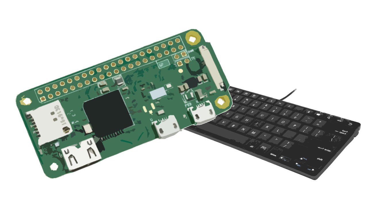
In this project you'll learn how to turn a Raspberry Pi Zero board into a keyboard or HID. Then, you'll write a Python script to make your Pi act as a keyboard.
because /dev/hidg0 doesnt seem to exist, so idk if ive just missed a step or what, but the pi does show up as a device on the host pc, so 🤷
errant grail
Using I2C, can CircuitPython (on the ItsyBitsy M0 Express for example) act as a device (slave) instead of a host (master)? I looked through Read The Docs and couldn't find anything except the master mode.
meager fog
nope just master for both i2c and spi
errant grail
NP. I'll just use Rx/Tx instead. Thanks!
 ruby atlas
Man, the Metro M4 (and any M4) is so much faster I'm not going to want to keep developing for the M0 😃
So fast (with pixelbuf help)
ruby atlas
I spent parts of today preparing for Canada Day and other parts refactoring pixelbuf to have ByteOrder classes much like Pin classes.
Next up: Pure python pixelbuf (and/or renaming it?) and the RGBLED base class that DotStar2, Neopixel2, and others will subclass.
Hopefully it'll all work well and be able to be made even faster.
meager fog
cool, looks rad
scarlet fjord
does circuitpython have HID support for gamepad emulation?
I can see docs for mouse and keyboard, but not gamepad.
I'd really like my joystick to be detected by my computer as an xinput device but idk if this is possible 😛
slender iron
@scarlet fjord in 3.0 it does
scarlet fjord
oh cool! is there anywhere i can read up on the documentation for that? is it on github? id like to take a crack at it 😄
slender iron
scarlet fjord
thanks 💖
slender iron
np
scarlet fjord
hmm ok turns out im running circuitpython 2.x(?), what does 3.0 need? can i run 3.0 on my Feather M0 Express?
i think i found it on github: https://github.com/adafruit/circuitpython/releases
is this tutorial meant to link to CP 2.3.1? https://learn.adafruit.com/adafruit-feather-m0-express-designed-for-circuit-python-circuitpython/kattni-circuitpython
ah, 3.0 is still in beta i assume
eyyyyy
and ive got it working in a game! 😄
scarlet fjord
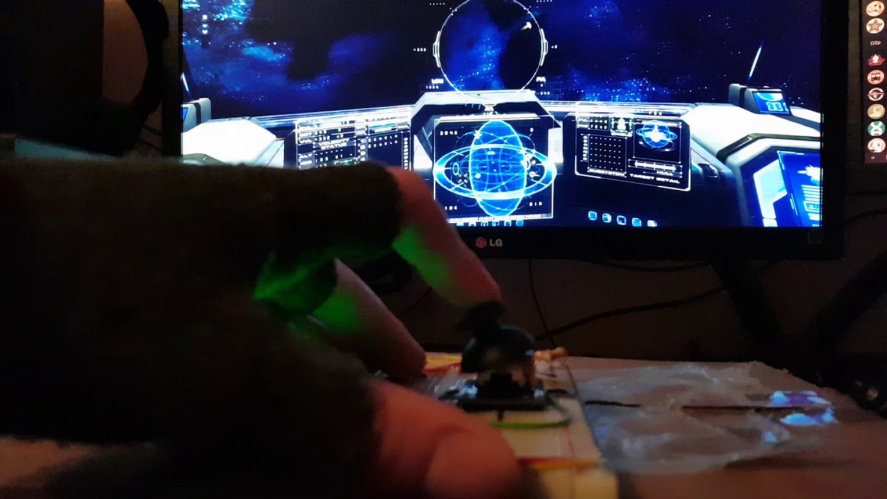
 tough flax
Hi folks. Is there a guide on how to create a c library and expose it to CP? For example if I had M0/M4 C code (or arduino) and I wanted to write a python wrapper and install it with cp?
I seem to remember something like this
scarlet fjord
so this is curious:
from adafruit_hid.gamepad import Gamepad
from setup import joystick_axis

gp = Gamepad()
ty = 0
tx = 0

def clamp(val, dmin, dmax):
    dval = max(dmin, val)
    dval = min(dmax, dval)
    return dval

while True:
    dx = joystick_axis[0].value
    dx = joystick_remap(dx)

    if not tx == dx:
        gp.move_joysticks(x=dx)
        tx = dx
    print("%4i" % dx)
This works fine, mostly...
except sometimes, when:
File "main.py", line 36, in <module> File "adafruit_hid/gamepad.py", line 133, in move_joysticks File "adafruit_hid/gamepad.py", line 174, in _validate_joystick_value ValueError: Joystick value must be in range -127 to 127
and idk whats going on, because clearly the number cannot be outside that range if im explicitly clamping it 
stuck elbow
wherre are you clamping it?
I see you are defining a clamp function, but I can't see you using it
scarlet fjord
oh, shit - i didnt paste that part in 😅
im doing it here:
def joystick_remap(axis):
    val = (((axis-1)/256)-127)  # remap 1 to 65536 so its -127 to 127
    val = int(val)  # adafruit_hid.gamepad requires this
    clamp(val, -127, 127)  # just in case a stray bit gets in there
    return val
so:
from adafruit_hid.gamepad import Gamepad
from setup import joystick_axis

gp = Gamepad()
ty = 0
tx = 0
invert_y = True

def clamp(val, dmin, dmax):
    dval = max(dmin, val)
    dval = min(dmax, dval)
    return dval

def do_inv(axis):
    if invert_y:
        axis = axis * -1
        return axis
    else:
        return axis

def joystick_remap(axis):
    val = (((axis-1)/256)-127)  # remap 1 to 65536 so its -127 to 127
    val = int(val)  # adafruit_hid.gamepad requires this
    clamp(val, -127, 127)  # just in case a stray bit gets in there
    return val

while True:
    dx = joystick_axis[0].value
    dx = joystick_remap(dx)

    dy = joystick_axis[1].value
    dy = joystick_remap(dy)
    dy = do_inv(dy)

    if not tx == dx:
        gp.move_joysticks(x=dx)
        tx = dx
    if not ty == dy:
        gp.move_joysticks(y=dy)
        ty = dy
    print("%4i | %4i" % (tx, ty))
ive tried it with int(val) before and after clamping and it still errors out occasionally...
scarlet fjord
... 😅
i am not smart
scarlet fjord
ok, wow there was actually a few things wrong in there... but its fixed now 😅
scarlet fjord
so ive done some testing
it seems the adafruit_hid.gamepad library uses the older Dinput device drivers, and it doesnt really play ball with a lot of games... Are there any plans to support Xinput?
for instance: BeamNg Drive supports this device, as does the Evochron (but thats not saying anything, that series supports anything your OS can detect, and its amazing), but Overwatch and Warframe (two games that do support Xinput and I have tested them both with my XBox Controller) dont detect it at all...
tulip sleet
@scarlet fjord
The HID capability in CPy reports the gamepad as a "Generic Desktop Ctrls" Device" (Usage Page 0x01), Gamepad (Usage 0x05). It has no control over what driver the host operating system chooses to use with that particular device.
Most controllers are proprietary and require a special driver. For instance, an Xbox controller does not obey the standards set up for reporting HID devices to the host. I tried a few different ways of reporting controllers and the current one was the only that works across Windows, MacOS, and Linux with builtin support. What OS are you using? Are there any to map Dinput to Xinput? This is not under the control of CPy.
tidal kiln
@solar whale could be. (.py vs .mpy). looks like i responded just at the right point to make things confusing. i'll let you continue. just ping me if you need any info on what i did or anything.
 crude fossil
@tough flax I've done a couple of talks on this and Damien gave a talk at Micropython Meetup last week ... I'll find some URLs for you.
tulip sleet
@scarlet fjord I did a little research and I see that Dinput and Xinput are XBox-specific. However, this program may be helpful: it maps lots of devices to an XBox controller emulation: http://www.x360ce.com/
manic glacierBOT
 upbeat plover
Any examples for "Creating and sharing a CircuitPython library" I have cookiecutter installed but i got stuck....
all the tutorials have "Temporarily unable to load embedded content. Please try again later." missing info
meager fog
@upbeat plover where are u stuck
upbeat plover
Learn about porting an Arduino library to CircuitPython with the VL6180X distance sensor.

Share your code with the world
i am very noob, first time trying anything like this so i need like step by step
any Tony D video? those are great cause i can rewind and rewatch what he does a few times
meager fog
hmm not sure there's one on making a a library
if you pop by tomorrow - there's a lot more people who can help
its a challenge the first time for sure 😃
you can start writing code just in Mu, get it working the way you want
then tomorrow we'll help ya get it into a lib!
upbeat plover
i use Atom... Mu font is horrible
tulip sleet
@upbeat plover The PDF version of the guide is OK for now and has the missing content: https://cdn-learn.adafruit.com/downloads/pdf/creating-and-sharing-a-circuitpython-library.pdf
Also this TonyD guide talks about adapting an Arduino library, so it may have the background you need. It's from Oct 2017, so there might be a few things out of date. https://learn.adafruit.com/porting-an-arduino-library-to-circuitpython-vl6180x-distance-sensor?view=all#driver-code
tulip sleet
@upbeat plover I've reported the "Temporarily unable to load embedded content. Please try again later." to the right people.
It's a 3rd party YouTube video to a Pycon 2017 talk.
manic glacierBOT

I have started to work on an SMBUS slave library and I need a better way to do testing than the script I'm currently using.
I've spent some time playing with pytest and I can now run fixtures and tests on the board and exceptions are transferred and raised locally.
The exception gets a custom traceback pointing to the correct source line.
Additionally I've done some simple assert rewriting, not as sophisticated as pytest which also avoids sideeffects.
So I think I have solutions for ...

Hi. this does seem to be caused by Kaspersky - I re-tried disabling all services and startup programs and found that Kaspersky was still running - I had to manually exit the Kaspersky program to stop it from running. The Gemma M0 was then detected.
Thanks for the testing! I did some brief research and I don't see this as a typically reported problem. If there are features of Kaspersky you can turn off, perhaps you can disable some but not all and get it to work. I'm not sure what would cause it to hang up the host computer. It may possibly have to do with the USB device switching identities under its nose, but that's just speculation.

Please add the BME680 CircuitPython driver to Pypi. Information below:
I am following the excellent Learning Guide CircuitPython on Linux and Raspberry Pi at https://learn.adafruit.com/circuitpython-on-raspberrypi-linux?view=all.
I have a BME680, not the BME280 and I would like to connect it to the Raspberry Pi using CircuitPython.
I installed the BME280 driver as per the instructions, hoping it might work, but I get the following error message:
RuntimeError: Failed to find BME280! ...
bronze geyser
so i've been bumbling about trying to write a circuitpython module/method that go into m0 standby mode (deep sleep) and then wake up through an external interrupt (I'm just testing with putting V+ to the pin...and...this seems to work: ```
STATIC mp_obj_t mymodule_deep_sleep(void) {
// store the original value for global interrupt enabling
uint32_t original_PRIMASK_value;
original_PRIMASK_value = __get_PRIMASK();
// enable interrupts by setting PRIMASK to 0
__set_PRIMASK(0);
// Tell the NVIC what pin we want to get an interrupt on.
// Looking at circuitpython/circuitpython/ports/atmel-samd/boards/itsybitsy_m0_express/pins.c
// I want to use D12. This is pin_PA19 in the mapping table.
NVIC_EnableIRQ(PIN_PA19);
// TBD: Interrupt priority level????
__set_PRIMASK(original_PRIMASK_value);
oh.,,, duh...i also do this:
oh...wait a second..i might have gotten too excited too early.
tulip sleet
the interrupt system is already enabled; we use it for a lot of things. prio 0 is the SysTick interrupt, prio 1 is USB, and everything else is prio 3 (lowest prio available on SAMD21)
in the datasheet read the PM and EIC sections (I think you read the latter already). You can do a "WFI" instruction to wait for an interrupt. I'm not sure the clocks are configured correctly for this all to work (ONDEMAND vs not for the EIC peripheral)
I am just reading the datasheet re WFI and PM - I don't have experience using them.
manic glacierBOT

Wow! That was quick, thanks!!!
On Sun, Jul 1, 2018 at 4:52 PM, ladyada notifications@github.com wrote:
OK try this!
https://pypi.org/project/adafruit-circuitpython-bme680/—
You are receiving this because you authored the thread.
Reply to this email directly, view it on GitHub
https://github.com/adafruit/circuitpython/issues/981#issuecomment-401635856,
or mute the thread
<https://github.com/notifications/unsubscribe-auth/AALNqaWA2y7x4uKyIxFBZiyjGChlm9Lkks5uCUS7gaJpZM4U...
ok! closing, re-open if it doesnt work (we didnt test it, just deployed)
 modest atlas
Need help with an esp8266
Used it to connect to Wi-Fi some time ago and it's stuck in this loop trying to connect and I can't do anything
raven canopy
@modest atlas Ctrl+C to end the program. then edit the code.py/main.py to change the WiFi credentials.
 marble hornet
WHOO! designed an embeddable metro compatible board yay (can't wait to break it!)
less than 1" square
modest atlas
@marble hornet samd?
marble hornet
yes 51, sorry metro m4 compatible
modest atlas
love it!!
marble hornet
@modest atlas once it is up and working I'd be glad to put some together and sell!
stuck elbow
@marble hornet won't the heat pad short those vias?
inside the chip outline, I mean
maybe better tent them?
stuck elbow
ah, in that case make the pad larger, and put the vias inside it
and add more of them
marble hornet
trestrict would work right?
stuck elbow
to thermally connect with the ground fill on the back
I have no idea what trestrict is
stuck elbow
I think so
you can stagger those vias in one row, to have better spacing for them
you know, like o°o°o°o
stuck elbow
hmm, not sure if that looks better
any reason why you have all the traces so tightly together on the bottom layer in the lower left corner?
you have lots of room there
marble hornet
near the flash ?
marble hornet
👍
stuck elbow
generally try to keep the traces straight if there is room
stuck elbow
same with the other group of vias
stuck elbow
saving time? how?
marble hornet
ordering pcb, shorting vias... scratching head... banging head on wall. then realizing gnd via shorted to a 3v3 via.
stuck elbow
you didn't run a DRC check on it?
 onyx hinge
@stuck elbow @marble hornet enjoying the pics and chat about pcbs
marble hornet
@onyx hinge Thanks! do you do any pcb stuff?
@stuck elbow with a couple fixes the drc checks out
stuck elbow
great
onyx hinge
Not much the past few years, sometimes I doodle up boards in eagle but never make it to fabricating
marble hornet
although some error will stay forever b/c i have two samd51 and two flashes for different size ships but it seems to work out fine
okay, so need to add some sort of rotation registration. if you were to use one of these what would you want to use to orient it?
all suggestions welcome
scarlet fjord
for like, aligning the chip on the pcb?
I'd be looking for a small triangle or something in a corner to align to 🤷
stuck elbow
or a dot
for qfn chips sometimes you just cut one of the corners of the silkscreen outline
 main meteor
I like to cut the corner and add a mark outside to make it more visually obvious.
In this board, it ended up making a goofy face.
 cunning crypt
I love it
scarlet fjord
◉つ◉
 ̄
 slender iron
@indigo wedge mind measuring the size change of your PR?
indigo wedge
yes I will, was just busy this weekend
slender iron
kk no worries. just checking
manic glacierBOT
Thanks again @mrmcwethy and @hotcarrier for the report!
I usually just do manual testing. @cefn did more formal testing here: https://github.com/adafruit/Adafruit_Blinka/tree/master/test/src
scarlet fjord
@tulip sleet I've had a play around with x360CE and it seems to do the job, but its a bit annoying to have to set it up for each game that needs it 😅
If you ever get the time, it would be amazing for an option to define the gamepads' mode as generic or xinput 😁
scarlet fjord
obv no rush tho
manic glacierBOT

 teal bear
@idle owl and the rest of the channel - who was the guy that made a video of your penguicon talk? (you are in the chan I think....
and really, anyone here want an all expenses paid 'vacation' to help me do video for https://www.pyohio.org/2018/
 upbeat plover
how do you make a pull request or suggestion for code on github?
https://github.com/adafruit/Adafruit_CircuitPython_CircuitPlayground/blob/master/adafruit_circuitplayground/express.py
line 67 needs to be replaced with something like
        self._lux = (self._photocell.value * 3.3 / 100) - 15
        if self._lux > 1910:
            return print('OVERLOAD')
        elif self._lux < 30:
            return    print('UNDERLOAD')
        else:
            return print(self._lux)
GitHub
Adafruit_CircuitPython_CircuitPlayground - CircuitPython library for CircuitPlayground
after changes lux should be same as https://s17-us2.startpage.com/cgi-bin/serveimage?url=https:%2F%2Fimages-na.ssl-images-amazon.com%2Fimages%2FI%2F81Lg-u9ZfVL._SX425_.jpg&sp=4ce55148f8e97e5491b81e4bc6bfbf5b
 fading solstice
@upbeat plover just add an issue in github for that repo
upbeat plover
okay
 long trail
Where can I find the daily or routine new builds for the Trinket M0 and the Feather M0? I wanted to test the DS18b20 fix.
tidal kiln
@upbeat plover have you ever done a pull request before?
manic glacierBOT

 tulip sleet
@long trail builds are here, whenever adafruit/circuitpython has a new commit (almost always by PR merge): https://adafruit-circuit-python.s3.amazonaws.com/index.html?prefix=bin
 astral vessel
I see the line "import usocket as _socket" in the socket.py code. Where is the usocket code? Or am I just totally misunderstanding what is going on here? I feel like I've looked everywhere...
solar whale
@astral vessel waht board are you using -- usocket is "built-in" to the esp8266 -- and that is the only place it is supported.
astral vessel
Well, my end goal here is to run micropython on a tricket M0 connected to an esp8266 running the AT firmware
I'm trying to figure out what I can use and what I need to change to use umqtt on the tricket
solar whale
What I do is send the data via uart to the esp8266 and then let the esp8266 handle the mqtt connection (to adafruit,io)
astral vessel
WIth the esp8266 running the AT firmware?
solar whale
ESP8266 is running Circuitpython
astral vessel
See that's where my setup is different
solar whale
yup -- sorry
astral vessel
At some point in the process the python code on the tricket needs to format the AT commands and send them via uart to the esp.
It doesn't seem like there currently exist any libraries to do that, so I'm trying to see if I can / want to write my own
solar whale
I've not worked directly with the AT firmware on an ESP8266. Only with micro and circuitpython.
astral vessel
I'm fine with what commands I need to send to the ESP, I've gotten that part all working both using a serial adapter and sending bytearrays from the tricket
What it seems like at that point is that I could use the logic from the umqtt code but I'll need to have the write and read call my own functions that handle communicating with the ESP
Or reimplement usocket ?
solar whale
have you looked at the umqtt libs here https://github.com/micropython/micropython-lib
 astral vessel
yep, I have indeed
solar whale
OK - hopefully someone more knowledgable will jump in -- good luck!
astral vessel
thanks 😃
raven canopy
<@&356864093652516868> and any who wish to join in, 30 minutes until the weekly meeting. ⏲
ruby atlas
I won't be able to make today's call, but my status update is: I've done some work on pixelbuf to implement a ByteOrder class and implement all the RGB/BGR/RGBW/RGBA classes that encode bytes per pixel and byte order details. These will be usable in the future NeoPixel2 and Dotstar2 classes that will be using the RGBLED base class that I have just started working on.
 umbral dagger
I won't make it, but I've been working with CP quite a bit. New guide went live today that's based on CP. Hug to everyone involved in writing and documenting the new rotary encoder support.
bronze geyser
i've been beavering away on a CP c module that sets up an external interrupt then goes into (m0) standby mode...i've written up what I've done (source is there too). I think I am close, but probably not handling the EIC correctly? If anyone has a moment ... advice VERY much appreciated....writeup: https://github.com/BitKnitting/wakey_circuitpython/wiki/Circuit-Python-and-m0-Standby-mode
GitHub
Contribute to wakey_circuitpython development by creating an account on GitHub.
idle owl
@teal bear That was James. I can ask him if he'd be willing to help, but we're already planning to attend. My tutorial request was approved. He's already on the hook to help me with that for sure. I don't know what his plans for the rest of the conference are, so I don't know if he's available. You could post your request in #general-tech or #general-chat as well, but don't do both.
modest atlas
can anyone help me on syntax here
import board
from digitalio import DigitalInOut, Direction, Pull

buttonA = DigitalInOut(board.BUTTON_A)
buttonA.direction = Direction.INPUT
buttonA.pull = Pull.DOWN

buttonB = DigitalInOut(board.BUTTON_B)
buttonB.direction = Direction.INPUT
buttonB.pull = Pull.DOWN

count = 0
print(count)

while True:
    if buttonA.value:
        time.sleep(.2)
        count += 1
        print(count)
    elif buttonB.value:
        time.sleep(.2)
        count -= 1
print(count)```@bronze geyser I'm working on that today also.
raven canopy
👋
tidal kiln
@modest atlas where?
raven canopy
Anonadillo?
timber mango
I did Dvorak three times with good long periods in between (2 years at a time in Dvorak).
idle owl
@raven canopy Armanonymous.
timber mango
Finally migrated back to QWERTY because of machines I don't own I needed access to.
modest atlas
sorry laptop died
timber mango
I do like Dvorak but only slightly more than QWERTY
modest atlas
looking to use i guess the range function but not sure how here
id like to use butonA & buttonB to toggle thru a set of number
timber mango
We're in a meeting, @modest atlas
timber mango
The usual shepherds are distracted. You can listen in -- we're on discord audio.
 turbid radish
Meow
tidal kiln
@modest atlas define your set of numbers in a tuple, use count as an index into that tuple
raven canopy
👍
onyx hinge
@slender iron just lurking today. Group hug and an extra hug to everyone reviewing pull requests!
turbid radish
Scott - thanks to everyone, Dan for the Crickit library support.
and Kattni for the GitHub guide
onyx hinge
hug reports to everyone who waits until 4.0 to do destabilizing work
raven canopy
@kattni for the git[hub] guide! Super useful! @jerryn for continued testing, "breaking", and fixing of all manner of things. @Dan Halbert for the DigitalInOut fix.
meager fog
here in text only
idle owl
@meager fog Do you have hug reports?
raven canopy
I have timeit in my brain when you talk about the cpu profiling... 😄
solar whale

Help manage your time and take regular breaks with this Pomodoro Timer project.
slender iron
GitHub
Contribute to wakey_circuitpython development by creating an account on GitHub.
timber mango
Yeah I'm working on an Arduino version of SLEEPDEEP.
raven canopy
I plan on looking later. @bronze geyser
meager fog
@idle owl hug reports to tannewt for doing the travis pypi stuff i would never have figured out, and a bunch of peeps in the community for trying out adafruit_blinka on a pi!
idle owl
@meager fog We'll be ready for your status update soon too!
meager fog
ok im around doing emails and supports
tulip sleet
GitHub
Adafruit_CircuitPython_Crickit - Convenience library for Adafruit Crickit robotics boards
onyx hinge
@slender iron no CP time in the last two weeks, but I have been doing fun hobby stuff with GPS-based precision timing. A friend and I tuned a 40 year old crystal oven to exactly 4,320,000Hz according to GPS.
idle owl
@meager fog status report whenever you're ready
meager fog
hhii
ok i finally sat down and make a MVP of adafruit_blinka on raspberry pi
its held together with twine, but it works!
digitalio, i2c (busio) and spi (busio) are tested. SPI is still minimal, but i2c and digitalio are good. the next steps are getting all our libraries tested and into pypi
UART and PWM will come later, have to be sneaky with those
for other linux boards like BBB or orangepi etc, we'll use mraa
if anyone here is an mraa expert, or have 'arcane' linux boards now would be a SUPER AWESOME time to help out 😃
thats it!
idle owl
@meager fog Thanks!
onyx hinge
timber mango
ARM Cortex-M0+ SAMD21
Working on SLEEPDEEP and/or SLEEPONEXIT.
ARM Cortex™-M Programming Guide to Memory Barrier Instructions
Application Note 321 PAGE 22
Example 1. Ensuring the effect of an SCS register-write is visible immediately
       SCB->SCR |= SCB_SCR_SLEEPDEEP_Msk; // Enable deepsleep
       __DSB(); // Ensure effect of last store takes effect
       __WFI(); // Enter sleep mode
Three Arduino IDE pathnames that are relevant:
_.arduino15/packages/adafruit/hardware/samd/1.2.0/bootloaders/mzero/Bootloader_D21/src/ASF/thirdparty/CMSIS/Include/core_cm0plus.h
_.arduino15/packages/arduino/tools/CMSIS-Atmel/1.2.0/CMSIS/Device/ATMEL/samd21/include/component/pm.h
_.arduino15/packages/adafruit/hardware/samd/1.2.0/bootloaders/mzero/Bootloader_D21/src/ASF/sam0/drivers/system/system.h
idle owl
@modest atlas If you have a status update, let us know 😃
raven canopy
FrequencyIn Module: didn't work this much last week; video game vortex. Tightened M4 numbers a little (leftover EXTINT async setting from tests). I've started a spreadsheet to help find a pattern in the results to attempt calibration; it's not appearing linerarly ATM. I may add calibration ability for the user side. M0 is still pretty much spot on.
Little Leslie amp: I have a draft design for the rotating assemblies, and most of the BOM for applicable bits. Intial budget projection...blown to pieces. 😆
BF3...
prime flower
stellaris>
onyx hinge
the only video game is https://www.terrycavanaghgames.com/dice/9/html5/
raven canopy
I saw that. Might check it out
modest atlas
nope just following along! just small random learning projects
idle owl
That is a status update!
raven canopy
Random thoughts... flew away. 😄
Thanks everyone!! Have a great Monday! Stay safe out there.
turbid radish
😃
modest atlas
happy 4th hugs
timber mango
Drink water.
raven canopy
That was me on Thursday. Stayed away from the heatbox.
timber mango
91 F in NW CT with 71 F dewpt
http://andrew.rsmas.miami.edu/bmcnoldy/Humidity.html
colemak is similar to dvorak I think
idle owl
@teal bear My tutorial is 2 hours, I think they all are. As far as I understand it anyway.
timber mango

 onyx hinge
can someone drop the link for the circuitpython-on-raspberry-pi again? I'm failing to find it in search.
raven canopy
😆
solar whale
Make hardware and interface with sensors super easy using CircuitPython
timber mango
My keyboard on my lap and I slouch -- no desk. ;) << wrong but true
(logitech K410)
Justin (Justin's Lucious Links) had a tendon issue so severe he had to stop typing for months.
http://links.net
solar whale
I like my trackpad