#3D Print Gulag
1 messages · Page 5 of 1
part of the goal was to have all the functions of a modern printer so heated bed included. its a very silly project
I hope to do nylon, ASA, ABS, etc on this someday though, once I get the money together for the enclosure panels.
he can then upgrade it with 3d printed parts once its able to print. that is the other thing he cant use another printer to make it. its just one of those silly challenge things
yeah, allot of the standard printer beds dont get hot enough for those either. like they say they will do 100c but good luck... maybe after you insalate the bed
and many of those fancy filaments need like 120
my stock ender3 pro bed can do 100c 😆 a bit higher too I think, cant remember what I took it to
Adding bed insulation is in my roadmap somewhere.
I have never tested mine, I know its firmware limit is 100c. dont know if it can actually reach it
not finding any rotary tool drill press plans that actually do what I want 😦
what I am wanting to make is like a 3 in one tool. at its core a basic press like an arbor press. able to swap the tool that go's in it for either a rotary tool, a soldering iron for heat sets or just a block for pressing bearings into printed parts.
Total list of remaining wiring:
- 2x JST fan connectors from mobo to rj45 breakout board.
- 3x 3 pin dupont connectors from second rj45 breakout board to mobo accelerometer pins.
- Mains power from c14 socket to relay, and from relay to bed heating pad.
- Bed thermistor to mobo
Non wiring tasks:
- Apply bed heater and build surface to build plate.
- Wire management.
- (after printer is running) final tramming with assistance of bed probe.
I'm so damn close to done.
Baring unforseen excitement, I'll have this thing spitting plastic in a day or two.
what kind of build surface are you going with?
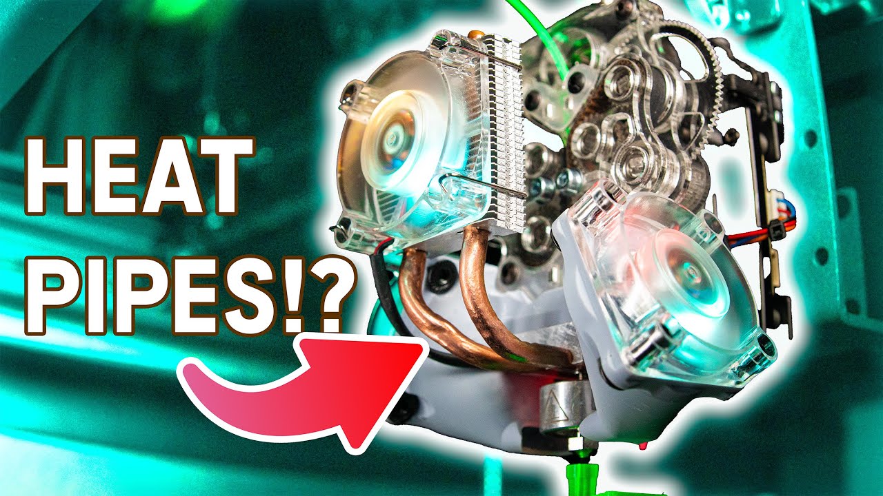
also this extruder is cool. he has been working on it for a while and its a very interesting design. using a pi cooler for head break cooler is an interesting idea and seems to work well. https://www.youtube.com/watch?v=MftDN3f-8nQ
#ad #anycubic #anycubicwashandcuremax Check out Anycubic's new Wash & Cure Max here: https://shrsl.com/49nfb
Thanks xTool for sending the awesome P2 55W CO2 laser cutter! If you're serious about laser cutting I can wholeheartedly recommend it. Check the link! https://geni.us/JAgoK and use the promo code properprinting for $80.- off on orders ove...
it uses belts to grip the filament, so lots of surface area gripping it and gets rid of allot of the odd little problems that gears have.
Magnetic textured PEI

invented this printer mod so I could make the sickest air gun possible, but never finished
decided to finally make a video about the work along the way
rotational axis printing can do a lot of cool things
modded a cr-10 and wrote the software myself hehe
The build surface is a rod. This is smart as hell
Hooked up everything except the bed power and booted the printer, the part cooling fan started out on full blast, despite the controller being convinced it is at 0%. Is it possible to wire it incorrectly and reverse the PWM duty cycle?
The fan direction is correct, so I doubt I have the power inverted.
if you turn up the fan speed does it slow down?
Klipper+RatOS
difference of active low vs active high somewhere?
Hmm. It looks like it is possible to invert the signal in klipper, some fans do it one way, others the other. You would think the fans supplied in the kit would be configured the same was as the provided software, or that they would add a note in the instructions or something.
Boom. It was as easy as adding
[fan]
pin: !fan_part_cooling_pin
shutdown_speed: 1.0
to printer.cfg
Figuring out what to do took a bit though.
The ! is the only diffrence from default.
Well, all axis homed, zoffset set, and tilt calibration has been run. Next step is to wait for the last cables (I'm using a temporary ethernet cable for the fans, and nothing for the accelerometer right now), wrap them up in a proper umbilical, and run bed meshes until I have the gantry trammed in properly.
Then apply bed heater pad, wire it in, and run PID autotunes before finally it is time for the first test print.
After that comes the never ending adventure of tuning and tweaking to get everything dialed in just so, starting with pressure advance and input shaping.
If I really wanted to, there is a 99% chance I could do a simple test print right now though.
look at the data sheet of your fan.
It might very well be that they chose this approach to enable a 0 RPM mode without having a "lowest PWM to achieve spin"
...makes the controller inside the fan way more complicated tho... weird...
Nah, it just has inverted PWM signalling from the board default
most 3d printers use 2 pin fans. no pwm signal, its going in to a FET/driver to power the fan
This one uses two plugs on the board, one for raw power, and then a second single wire for PWM. It doesn't uss the tac pin
Had to make a special cable for it
The fan itself had a 4pin JST
But the board wanted 2x two pin JSTs, but with three wires
thats.... not how 2 pin fans work.
2 pins: power, ground
3 pins: power, ground, tacho
4 pins: power, ground, tacho, pwm
The Ratrig instructions had it all laid out
oh wait, I misread what you said
🤦
normally 3d printers use only 2 pin fans, though some boards I guess do support pwm fans
They are doing black firmware magic to run a 4 pin fan on two, 2 pin fan headers
thats not black magic, thats just realising that the majority of its users are going to be connecting a "standard" 3dp type fan to it, which are two wire
I'm guessing that they are just slaving two fan headers together with Klipper macros, and telling the firmware to drive one with PWM and the other on at 100% full time. Then they just take the hot wire from the PWM driven header and feed it to the PWM input on the fan.
The ground pin on the PWM header is meaningless then.
potentially
Clever way to work around a lack of 4 pin headers on the board.
actually... that would explain it.
3dp does basically all its power stuff by switching 0v/gnd rather than vcc (ie needing to be active low instead of active high I guess). this would probably cause the pwm signal to be inverted relative to something like a pwm fan that can receive the signal directly
But, since the config they ship in RatOS is tailored by default to the exact config (down to the fans) that I bought, that is really weird.
The only other thing I had to change in the firmware was swapping from the default 300, to the 500.
Guess i shouldn't be supprised. Their build instructions are dogshit in a lot of places.
I miss youtube videos about 3d printing rather then just trying to sell you the latest fad printer...
Just a totally normal picture of my Ender 3...

now do a Dr D.flow and make yourself a 1m printer, and nest even deeper!
This one cost enough as it is! 
That's a unit of a printer
its easy, you just print the bigger printer with your new big printer
poor man needs to move to a state where fun is permitted
so one of the things that has been holding me up on getting an all metal hotend for my printer is the problem of thermal paste. everyone says you have to use boron nitride paste, its the only paste that works at these temps. and if you dont use it you will get clogging hell any time you try and print low temp filaments like PLA.
I think this boron nitride thing might be BS... ok the thermal paste go's on the heatbrake, on the cold side where it interfaces with the heatsink. this heat sink is small, it gets directly mounted to plast and has a plastic fan directly mounted to it. its a heatbreak, ment to stop the heat from climbing up out of the hotend. I dont think it really gets as hot as is implied here. I looked up the operating temp of thermaltake's TG-7, the thermal paste I normally use and have on hand. its rated up to 250c.
is there really any reason to think that the thermal paste will go over that temp when probably the max I would have push this too is 260 but most of the time not going over 230 or so?
the big question is: what is the life of the tg-7 at 200-250c?
the datasheet for it contains precisely 0 useful information
additionally the Slice Engineering boron nitride paste apparently has almost 10x the thermal conductivity of tg-7 (31.4 W/mK vs 3.3 W/m-k).
what I am reading is the cold end of the heatbrake rarely go's over 80.
you typically want thermal paste in three places on a hotend. between the heatblock and heater, the heatblock and thermistor, and heatbreak and coldend/heatsink. two of those will be at hotend temp, and the other will be "cold"
and yeah, boron nitride is really good but its also fucking exspensive
well I am not planning on removing the thermister ir heater
im seeing 10 bucks for 5cc right now (from slice). but that looks to be a special deal (down 15 bucks)
well i might have to remove the thermister, that needs replaced
its 15 bucks for a tiny tube and then shipping, and even buying it on scamazon its only sold buy this one company and always has that shipping. so its around 22. not much right? well it fucking is for me
despite everything I just said... a sufficiently rated cpu-type thermal compound should be fine
when you add to that all the other shit I am looking at around 60 bucks just to swap out the heatbreak, I can buy a full extruder for that price
only i cant buy one that is actually compatible with my damn printer
at this point I am ready to just give up on the idea of printing ASA anyway. its more exspensive then PLA and its fumes are apparently really bad for you even if it dosnt stink. I dont have good enough ventilation.
ASA and ABS both contain styrene, and that is where the fun fumes come from.
I'm not sure where the idea ASA is safer to print than ABS comes from, but I see it everywhere. It may be safer but it isn't safe (without precautions)
I'm in a pretty poorly ventilated place, so I'm mostly interested in nylon and such that is less likely to try killing me. I'm still gonna put a filter on the enclosure when I get to the point where I'm adding it.
Next time you think a print went poorly, remember this poor sucker:
https://www.reddit.com/r/fosscad/comments/17ca4z1/rate_my_c96_ar_grip/

Reddit
Explore this post and more from the fosscad community
just some minor layer shifts, I am sure its fine!
Surprised that held on
hm, elegoo now has ASA filament and its $16 a kg
Haven't tried Elegoo's filament yet. Guess I might have to!
oddly they dont have the ASA on there website, its only there amazon store that is selling it right now.
also only in black so far. but it looks like they expanded there colors a bunch for PLA and now even have silk
I have tried there black/white/gray PLAs and those all work really well and are the cheapest. I mostly stick to white for the reason everyone else avoids it, it shows imperfections in the prints really well and sense I do allot of mold making that is important.
friend is printing some intake adaptors for a motorcycle. carb to intake pipe. what filament would be best for that? my thoughts were that PETG might get a little to warm there and ABS would have a problem with any fuel vapors.
arent carburators almost always out of metal?
I think plastic is not good for a part that comes in contact with gasoline but fuel tanks plastics should be fine tho not neccesarily in a vacinity of heat
the air cleaners that go in this spot on carbs are often plastic. that is fine as long as the plastic can stand up to a bit of fuel vapor and moderate heat. stuff like this is normally made of PP I think and that was what I told him would probably be the best option but its a bit tricky to print.
"a bit tricky" is good - doesn't poly propylene require fume extractors and a heated print chamber?
I dont think it requires fume extractors or a heated chamber. at least if you use the GF version to prevent warping, might still need a draft shield or something, not sure. it does require special bed prep because it dosnt stick to anything and its fairly high temp both for bed and nozzle
ahhh alright
I suspect PP is the ideal option. was just wondering if there was anything easier that could work. like maybe I am wrong about the abs/asa problem, or maybe it dosnt get to hot for PETG after all as that has good chem reistance
carburators are also really known to "want" smooth walls for good air/fuel mixture - maybe asking in #1050573453503242241 aswell might be of use
Long story short, PLA and ABS are both bad choices as you suspected.
https://www.irjet.net/archives/V6/i7/IRJET-V6I7187.pdf
you mean PETG?
It is clear from the results that exposure to gasoline has its effect on both the materials, but a more adverse effect can be observed on ABS material. PLA has lost 73% and 64% of its tensile and flexural strength respectively, but ABS has lost 97% and 99.6% of its tensile and flexural strength respectively. It can be said that ABS has completely lost its strength and can be said to have ‘failed’. It has also become soft, while PLA has retained its hardness. It is concluded that ABS is seriously incompatible in applications involving direct or indirect contact with gasoline.
oh
yeah I figured ABS would not get along well with gas but I am unsure how much it would actually be exposed to in the intake pipe. I know there can be a little vapor in there when you shut the engine off. at least on a car's carb.
do you think PETG could handle the heat there? I dont think it gets very hot but maybe combined with the sun it might be too much
ABS could be coated with resin perhaps
If a resin could be found that had better properties.
Or, it could just be fine. Nylon would probably work.
epoxy is almost as weak to heat as PLA but has good chem reistance, PU is better with heat but I dont know about its chem reistance, but I think its bad
Nylon has good chem resistance.
And if you can print ABS, nylon is within reach IIRC
yeah, figured Nylon would be an option. but its a bit of a pain to work with, like GFPP.
I dont know if he has the drying stuff needed to do nylon.
lol, have him get some trimmer line, throw it in the oven for an hour and print with that
Trimmer line is a pain to get a good print with from what I know.
Lots of tuning required.
GFPP is really the way to go isnt it?
you can actually get it fairly cheap right now, like 28 bucks for a 500g spool
It warps like crazy
I thought the GF version was fairly stable if you can get it to stick to the bed?
I don't know, fiber may help.
someone here was playing with it a while back. thought it might have been you but I am bad at names
Wasn't me, maybe try a search?
it was Mazda, M names. why I got confused.
my apartment is cold... I need something to print
the throttle plate would be between the carburator and said pipe, right? in this case its probably fine actually but heat in such a compact thing (tho with good air flow) might still be meh
na, this is just the intake pipe, after the carb leading to the air filter
well an adaptor for the rubber intake pipe. this carb has a slightly larger connection point then the stock one so he needed an adaptor
yea but is the throttle plate inbetween the carb and the pipe or is the plate right after the intake
its all before the pipe on the engine side
so its a moped without a throttle plate?

like this?
i feel some sort of miscommunication happening here
its not the intake pipe as in the pipe between the carb on motor, its the pipe that go's from the carb to the air filter. I dont think I have even seen an engine where the throttle plate isnt just intigrated into the carb its self so I am confused
it probably is a 2 stroke as its a dirt bike

the light gray bit is the 3d printed adaptor
OHHHH OKAY
lol, didnt mean like a plastic intake manafold... I mean who would be stupid enough to make that out of plastic... oh wait, modern car companies would
yea exactly
theoretically there should be no backdraft at all and also pretty much no heat so I'd actually guess its gonna be fine if its up to 80°C resistant and lightly coated
so I am back on my silly lamp design again. trying to figure out how to keep the bulb from being able to swing to much while being susspended like this.

if it's carb to filter that means gasoline resistance isn't as much of a constraint.
because no fuel has been introduced at that point
when you shut off an engine the vacuum stops. the last puff of atomized fuel in the carb often drifts up and into the filter area. that is why when you pull the filter off an old engine like that they smell like gas
its not allot, it might be just fine, really dont know.
That's fair
Creality being based:
https://store.creality.com/blog/orca-3d-printed-ar-15

I'm pretty sure that picture isn't an orca though. The upper certainly isn't, so that is probably a hoffman super lower (I think). He has several lowers, the orca is a custom lower/upper pair.
This is an orca, as you can see the line between upper and lower is not in the normal location, and would not allow a normal upper to be mounted.

ahh the glory of the AR the bit that matters oddlly enough does not
Any of you have much experience 3D printing Star Citizen ships?
@keen shuttle made this one


So, was looking at some models I found around.. most seem to have been ripped from the web viewer and have pretty terrible geometry. Lots of overlapping faces and whatnot. I wanted to print one, but worried without a better quality geometry, it's not going to work great.
And while I could remodel them, using that as a reference.. that'll take a long time.
Was debating doing something simple like a 100i to make it easier
I've seen a couple models which looked like they had been re-built.
And I have one or two which appear to not be STLs generated from a parent mesh, but proper game geometry. Things like all the faces are properly mirrored, vs slight differences in how areas have been decimated into tris
Which is something I can work with.. but most everything is a kinda terrible STL
Anyway, was just trying to see what others have been doing and if I'm missing a better way
I can tel lyou from printing my Space Engineers ship that if you dont have good geo for printing your not going to get anywhere. overlapping faces, internal geo, meshes that are not water tight. all of those things can make it so you cant even slice the model. converting a game asset or worse to a printable one is a good bit of work.
I searched and searched for a way to automate mesh cleanup and none of them worked worth a damn. I ended up having to do it all manually

it actually works...
managed to model a tiny working worm drive.
that is easy to print
That's pretty cool. Useful in like tiny models
its going to run the winches in my crane lamp I am working on. I needed something to prevent back drive and trying to do reversable ratchets or clutch packs at this scale would have been insane
I somehow managed basically zero backlash first try. no idea how that happened
esspecially seeing as I used the horrible bolt and gear addons built in blender and just eyeballed everything
If it works🤷♂️
Yeah, that's what I was worried about. Working from a game asset is a lot easier than a baked STL though. At least from a game asset you often have clean lines and quads already
Zero backlash is awesome.. but usually means you've got very tight pressure on a compliant material.. over time it'll start to wear and loosen. Might have to keep that in mind if you expect it to move a lot
Sorry if I'm stating the obvious there. >.> This problem comes up a lot where I work
yeah, it should be ok. this will have very little load on it and not move all that often. its just adjustments for a lamp, the key was something that cant be back driven.
I could not find a good way to design proper worm gears with the tools and skills I have so I eyeballed it and somehow actually got it on the first try. been fiddling with the prototype all night to see how it wears in and if I need to make any adjustments
eventually did pick up a little bit of backlash as you said but now actually runs smoother. was probably just wearing off the seam nubs from printing and that is why it had no backlash at first
Finally caved and ordered filament from elegoo. 5kg is on it's way
I just added up all the filament I have used sense I got my printer about 10 months ago. I am on 13x 1kg spools. almost done with number 13
should I be changing my nozzle after running that much filament threw it? its all just normal PLA, no abrassives
well dosnt it wear eventually even with none abrassive filament
I should swap to my knockoff CHT nozzles anyway. I just dont want to have to retune my temps, these new ones are copper core so they are going to melt a bit faster, betting I will need to drop my temps a bit
had a pack of them sitting on my desk for months
They didn't have nozzles for the 4 pro on the elegoo site
Only nozzles i could find were suitable up to the 3 pro
yeah, I dont know why the hell they switched to a propritary nozzle. that is really annoying. I saw something about a type of nozzle that might work for them...
hm, maybe not. it was the creality high flow nozzles that some people thought might work but it looks like its a little to long or something.
apperently you have to email them to order the nozzles, that is fucking stupid.
Yeah. As is forcing people to use their software, which is outdated af
Can't get ultimaker to import the profile for the 4 pro
I'm sure decent knockoff nozzles will pop up soon
there should be profiles for the 4 by now. I had to make a custom one when the 3 came out because no one had them. might need to use the beta branch of the slicer you like
One thing I've looked at for similar things is getting off the shelf gear assemblies/boxes, or even using little lego ones I put together
Since.. I'm really not so much a fan of 3D printing, as someone who likes to make stuff and likes the flexibility of being able to print off something I can draw on the computer, fairly precisely. Sure beats trying to cut and file parts from plastic by hand.
Totally going to try and make a real life SC-style glowstick now.. model it up in blender, print it out, add electronics, etc.
lol, just 3d printed a replacement caster for my chair because one of them broke and the damn thing is actually stronger and smoother then the ones that came with the chair
when you look at the hardware and filament required its not really worth it if you need a full set. but if you need one right now its actually a nice fix
that is if you have the size of bolt and 608 bearings on hand but who owns a 3d printer and dosnt keep a stock of 608s?
Replacing the casters was the first thing i did when i got my chair, hate the 'hard plastic that damages the floor'-type.
I am amazed the cheap plastic ones on my chair lasted 10 years without breaking.
uhhh
What's a 608?
Those the skaeboard bearings?
Or rollerskate, or whatever? See a lot of 3D prints using those
Skateboard bearings, yeah. Small enough to be useful to tiny projects, but not too small to be useful for larger stuff, and cheap as shit.
They are basically the perfect size for nearly anything 3d printed.
Any of you built models with LEDs in them that were battery powered, then made it rechargable battery over USB or even Qi wireless?
Thanks! Was just looking at some prints and realized I indeed have no bearings (hah! pun intended).. giong to go grab some. Hate looking to work on something and realize I have to go buy a bunch of odds and ends.. so been looking to build a stock of basic things I'd need to do most of the kinds of stuff I'd be interested in. Like I have metal rods, all sorts of plastic, stiff wire, soft wire, wood, etc.
I have m3, m4, and m5 bolt kits for that very reason 😛
Yeah, got some bolt kits
I watched a lot of adam savage videos.. and every time he'd reach for something and go 'I always use this'.. I'd go run to Amazon. ;p
At least, for things I knew I might need.
The 1x2x3 blocks were a perfect example. Awesome
Bought a pack of cheap skateboard bearings years ago (for a skateboard actually, but they didn't get used). Have since used several in printed projects, like strengthening the z-axis on my ender 3v2. I didn't like how the top of the screw was free floating, so i printed a bracket which holds a bearing around the screw and bolts down to the top of the frame
Think it was like the third print i did
Any true printer nerd will use a lot of their early printer cycles on making stuff for the printer.
For smaller printers (and more importantly cheap leadscrews) you actually want the top free floating. Cheaper screws (including most that come with creality printers) are bent slightly, and constraining them at three points can cause them to bind, which fucks with your layer consistency
It had some play in the bearing, just wanted some support because i was sure i would catch my sleeve or something on it and either bend the screw of rip the entire printer of it's shelf
Filament from elegoo finally arrived, can't say I'm too impressed by the packaging
Looks like someone went wild with the packaging tape, and left it at that
No box or anything
odd, mine comes in nice boxes, the spools are vacuum bagged with desicant as well.
That they are, luckily
printed some riser feet for my desk to make it work better with my new chair height. less pain in my hands from using the mouse or typing
Printer is "done", I'm about to run PID autotune for the bed \o/
I had the "gets lost and crashes the head on the side during z tilt adjust problem, but I'm about 89% sure that one of the drive pullies came loose and was slipping. For some reason the flat side of the stepper shaft was not under the grub screw, and I'm sure I made sure it was when I was assembling. If it happens again some locktite may be in order.
I'm pretty sure that was the issue, since after I realigned the pullies and tightened the bejesus out of the grub screws, it is running smooth and straight again.
No one told me how much work it was to get a custom core XY running  ||I knew how much work it was going to be, I'm just whining||
lol, so if I ever want to make my own XY I have all the belt I need. I ordered 2m of it for a project I was working on... they messed up and sent me like 15
wtf am I going to do with all that belt? I only needed like 600mm
Well, I'm attempting a benchy, wish me luck 😛
I need to tell the slicer to calm down a little with the part cooling fan
On my Ender, I had to tell it that it was OK to run the fan while bridging, with this thing I'm gonna have to tell it to settle down a little.
I haven't done any of the advanced calibration stuff yet, and the print is looking nice. Even z offset was set quick and dirty to something "good enough for now".
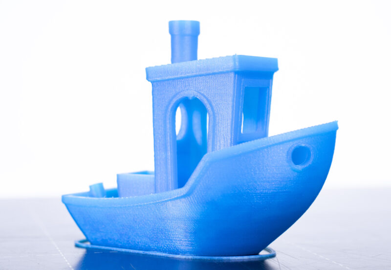
Well, it isn't perfect (there is a line on the hull that matches up to where the stern rail starts), and it is obviously made with a .6 nozzle so the layers aren't quite as fine as the .4 I'm used to, but for a quick first print I am fully satisfied with the result.

Printed in Polymaker Polylite black (their midrange PLA)
Some kind of line at that point on a benchy is normal, not that aggressive though
Yeah, this is a overhang almost. To the point where it makes me think it was a layer shift if it wasn't for the other side also being bumped out, just a lot less.
its known as the "benchy hull line", and is typically caused by where the slice changes from infill to top layers on the floor. Prusa has an article on it: https://help.prusa3d.com/article/the-benchy-hull-line_124745
The 3DBenchy is a 3D model designed by CreativeTools specifically…
Yeah, but a line this extreme is a sure sigh that I have a bunch more tuning to do
Which i do.
Pressure advance would probably be a good place to start.
For a first benchy, that's pretty decent
You gonna print a massive one at some point?
three days later
A huge benchy would be fun.
Maybe not giant, but large enough that it makes the printer look normal 😛
So, I guess I won't have to calm the part cooling fan after all.
I got tired of the power sockets just dangling from their leads, so I found a mountable plate on printables that seemed to match the desired profile and just sent it. Hey, it did the benchy ok.
No fan except for during bridging for most of the print, and then it came on with a vengeance when it got to the housing that surrounded the socket. Turns out it was the minimum layer time. If a layer takes less than 60 seconds the slicer is set to run the part cooling fan. Which seems like a good idea lol Not changing that, at least for PLA.
part cooling with a small jet engine?
I just have to keep in mind that small PLA prints are going to be loud, and that "small" is relative.
The part cooling fan is a 4028
tuning a fully custom printer like that sounds like it would be allot of work.
and not quiet.
I hooked up the accelerometer today, and got comunications errors. I doesn't like the cable I used.
So I need to remove the unshielded adapter section I think, and if that fails upgrade to a better cable.
I can't make it any shorter.
But the accelerometer is optional and not a big deal if it isn't working.
well it sounds like it makes tuning input shaping WAY easier.
Thankfully, 90% of the software config is already handled by RatRig as long as I use their packaged version of Klipper/Mainsail
anyone know how far you can push speed and accel on a printer without input shaping if you dont mind some ringing? I want to speed up my printing of functional parts where I dont care much about looks.
I was really annoyed when I had to spend 9hrs yesterday just to print riser feet for my desk. and that was at 0.8mm line widths and 0.24mm layers
Huh. The default config for this thing is set up to automatically push previous nozzle priming piles off the bed. Instead of just going straight to the corner, it goes in to beside where it is going to purge, and then side swipes it.
Also, unlike Marlin it doesn't do a purge line, it spits out a little tear drop pile, then lays a bridge out from the top of that, before sticking the tail of the bridge to the bed.

Complete with running the part cooling fan during the bridge part of that.
I'm assuming that is just a klipper thing.
But I have never had a klipper printer before, so...
So far I have resolved that any future printers will be forcibly klipperized.
||Sorry, I'm gonna be in "new toy mode" for a few months||
Does Noctua make any ultra quiet 4028 fans? Asking for a friend
if you mean 40mm wide and 28 deep - I think they do!
Not particularly quiet when going full tilt but should be reasonable at half speed
They make a 4020, but the static pressure is bad.
And since the whole point of this fan is to move lots of air down a small duct, there really is no choice but put up with it being loud as hell whenever it is on.
My current print seems to be designed to make the part cooling fan run for as long as possible.
Marlin doesn't do the purge line itself, those are typically a function of the slicer, and can be found in the pre-run gcode (along with bed levelling, etc).
It's possible in klipper that it's a part of the pre-print macro (which is the same thing, just part of the printers config rather than it's profile in the slicer, which would just call the macro instead I think)
Yeah, start gcode is all handled by the firmware config in klipper.
You just issue START_PRINT
with starting temps as parameters IIRC.
That's a pretty smart way to purge tbh
The UX for this printer is so much better than for the Ender. I wish I had klipperized that printer years ago. I had everything I needed hardware-wise just sitting there (spare raspberry pi, etc).
Instead I installed a slightly better version of marlin and called it a day.
Mainsail is so slick and it makes everything easy.
why an axial fan instead of a blower? I thought blowers were just better for part cooling
fairly sure you can get blower style fans that will move the air you need at the pressure you need without sounding like an EDF
I really don't know. Ask the designers of the EVA 3 printer head I guess.
It wouldn't actually be hard to convert it to any fan I want , since the duct just hangs off the back of the toolhead with a pin.
Top: 6" cat6a cable hanging loose
Bottom: 5' cat6 cable in the main umbilical

I have a 5' cat8 cable on order. You will work, and you will like it.
The ADXL345 needs high frequency signaling all the way from the motherboard to the printhead. Most solutions assume the cable isn't very long.
On my printer 5 feet is just about right.
And since I'm stubborn, I want it to run though the main umbilical.
Which means it must be shielded.
I'm a little surprised cat6 didn't cut it, but I think it would likely work if I wired it directly to the motherboard without the adapter cable I made. Either way, I'm gonna direct wire the cat8 cable, and if that doesn't work in the umbilical I give up.
Are you using the pairs in the cable, or just treating it as a collection of wires?
IIRC, one pair is carrying power, and the others are doing whatever signalling the chip uses.
pins 1 and 2 are ground and vcc
Because to properly take advantage of s/utp you need each pair to be one signal (and its ground, though the common ground is "okay")
cat8 has shielding for each pair, so I'm willing to bet that will help a lot.
And as i said, this time I'm gonna strip one end and crimp the motherboard connects directly to that instead of using the short adapter cable I made earlier.
So the ADXL345 is directly soldered to the rj45 socket, and then the cable is hooked straight to the pins on the board.
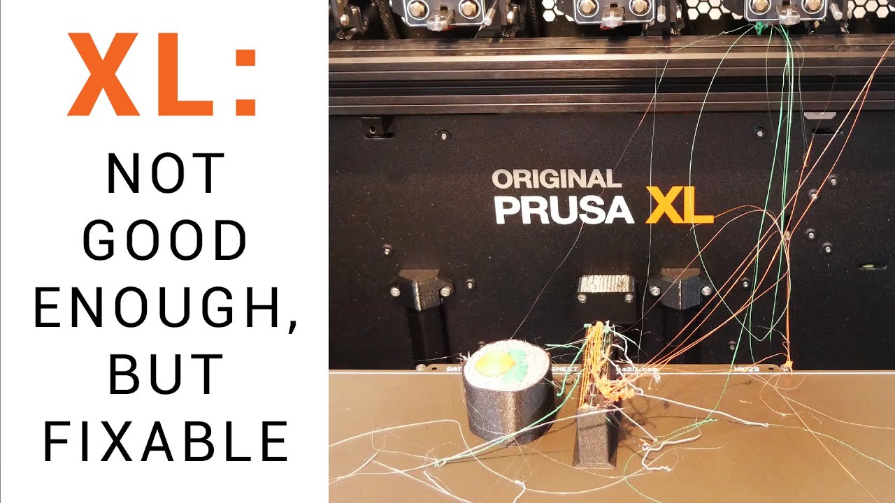
Anyway, looks like Prusa is having issues:
https://www.youtube.com/watch?v=C1a2c-qeTQw
Check out my 2nd channel, TT Racing: https://www.youtube.com/@ttracingYT
A QUICK UPDATE video using non alpha firmware: https://youtu.be/bVY3S22L4EY
It’s been delayed for some time and the price hasn’t gotten any cheaper, but finally my 5 tool Prusa XL has arrived. Was it worth the wait? So far, the printer is quite undercooked. In this video ...
looks like gen 1 issues on a system that is more complex than they realized most should be fixable but that will take time and I suspect that these printers did not have nearly as much testing as the team may have wanted because they were running behind
Printed some brackets so i could mount my mini pc in the patchcabinet that we're gonna install today

oh very cool
any reccomendations for cheap 3D printers that work well with minimal difficulties?
what do you wanna print with it?
cosplay or miniatures?
not for miniatures, for general manufacturing around the house
what do you consider cheap?
a printer for manufacturing things like doorstops and the such
sub 500 dollars
Now that I have a decent job
but I don't want to blow it all away
I want to use it wisely
last gen elegoo maybe?
added to cart
cat8 for the win!

The noise levels aren't even high, and this is a 5 foot cable.
Now I just need to take my umbilical apart and run this cable in place of the old one.
Which will be fine since cat8 is double shielded.
You can get double shielded cat 6, i was about to order some for running in my house
Ordered non shielded though, a friend who builds networks for a living said it doesn't really matter
A monoprice 5' cat8 cable was about $15 on amazon, so I decided to go big or go home.
And it very much does matter for any kind of distance or speed.
Yeah, cat8 is for long distances or very high speeds over short distances.
cat6 or cat6a is more house speed.
Outside of things like runs from a switch to the home server or whatever, since depending on how many kids you have hitting the plex server or hatever it doesn't hurt to have a fat pipe.
Cat6a is what we're gonna use
10 gig at 100m
so resonable.
In an industrial setting cat6a shielded could be required for emi resistance, and could be a good idea in a house if doing something dumb like running ethernet right beside power lines.
Which is part of why I went to cat8, I'm running this next to fan and stepper cables.
Yesh, nothing close to power lines here
Holy crap, best way ever to get a perfect arch umbilical that doesn't sag or try to flop over: Put a cat8 cable in it.
It almost acts like the ones some people make with spring steel wire in them

Anyone worked with threaded rod and tubes? Wondering if I can fit an M3 all thread into a carbon fiber tube or the like with a 3mm ID. Or do I need to give it a little tolerance and go like, 4mm ID?
m3 has a major diameter of 2.98mm, so should fit in to something with an ID of 3mm... assuming that it isnt actually smaller
(I havent tried it myself, just looked up a metric thread chart)
I was wondering about that. I looked up some M3 spec drawings, and I saw that the '3mm' was indicating the outside of the threads, but it didn't have any further detail of what the tolerances were. Obviously, my carbon fiber toob needs to be the right diameter too.. so I guess we'll see
Was also trying to see if I could just get a cap to glue on the end of the carbon fiber instead of running a threaded rod down the whole length. It's not load bearing.. just providing spacing
But I wasn't sure how I'd find like, a self-tapping M3 standoff. I plan on putting plates on either end, and run a screw into it.. or have the all-thread the full length and put a nut on it.
I'd rather the screw though, and just somehow tap into the carbon fiber.. add some glue or something.
Hm. Icould just use standffs.. still have the 3mm all thread run the length.. screw standoffs on each end, then able to push those between the spacer rings and screw in from the other side
Trying to make a fancy looking glow stick.
Almost.. like a custom lightsaber, except the handle itself is the lit tube.
if you get threaded rods they will most likely not arrive perfectly straight.
regarding the diameter - if the hole inside is 3mm inner diameter it will fit. if you expect that the threads will hold you need to choose another diameter and cut into the carbon tube. its also much dependant on the length you want things to be

Depends on where you get the all thread. A local hardware or plumbing supply shop should stock them so you can look and make sure they’re straight enough for your needs.
Also, they don't hve to be perfectly straight.. the threaded rod is meant to support tension, while the carbon fiber tube will handle compression. They need to be straight enough to fit in the tubes, and even then, only for like, 100-150mm long. I have a vise I can use to get bend them straight enough
I would have preferred something like a steel rod with threads cut into the end. Or I could cut threads in it myself, but I'd rather not at this point. If this prototype all works out, I'll worry about optimizing things.
Thanks for the details though, this helps. Cause I was also wondering if I could cut threads on the inside of a CF tube. While pultrusion tubs could be brittle, there's ways it might work.. but then it won't work in compression so well.. so eh. For now, I figured a CF tube around a steel all thread is best.
Though, realistically, it's just a glow stick housing. I don't need it to support my weight or something silly
However.. I also lerned that not only is CF tubing cheaper than metal tubing for this and the battery casing/LED mount.. CF tubing (especially pultrusions), should have equal or better thermal conductivity to copper or aluminum along the axis of the fibers.. and roughly half or a third of that across them.. meaning it could insulate the batteries from the LEDs to some degree, while sinking the heat out laterally to either end. In theory. It depends a lot on the source and type of carbon in your CF tube.
But even worst case, it's still close to a metal.
did you take note of the whole submergible situation?? The one made of carbon fiber and why it imploded?
Vaguely. Again, this needs to support all of 100grams of load. Not 1 million.
I think it would be best if you post a WIP of what you're designing :P
I know its a star citizen themed chemical light / glow stick adapter of some sort
Regarding cooling: metal strongly recommended
My choices were mostly convenince.. I want it to look decent.. like straight and whatnot.. so I could chose plastic rods, all thread, brass rod, etc. I was trying to figure out which would be not crazy expensive, look decent, and I could get it commonly on like, amazon. Also, I knew I could be generating a lot of heat, and batteries don't react well to a lot of heat, so I wanted to at least have that in the back of my head. Of done tons of LED work in my professional life.. and usually the main problem is getting rid of the heat.
ohhh I see
Also, my design work was around 100W LED power. Literally brighter than the sun. This is targetted to be around.. 1 or 2W.
I think carbon tubes are a great insulator - maybe ok for 5 W
I did a little researching, and they should have thermal conductivity around 100-200 W/mK, where aluminum is around 200, copper, 400. But some could be as high as 500. It's really hard to tell without testing the exact stuff I have, but yeah, for the magnitudes I'm talking about, I'm good. It's at least better than plastic. I could also easily put a thin metal foil between the LEDs and the CF tube (I'll want to put a reflective layer down anyway), and that would dramatically improve it. Anything that conducted or radiated into the CF tube would then conduct better along the tube than through it to the batteries. Also, the much larger surface area, spread out by the CF because of it's anisotropic thermal properties, would improve it even better. Adding that metal layer would further help.
So I could probably design it up a little bit more to handle even dozens of watts without issue.
The main thing is I wanted the design itself to be flexible enough that I could tweak as needed.
I can do a quick sketch.. I'll be modeling it up in blender soon either way
that would be pure carbon strands afaik
The addition of epoxy makes it horrible
Here's the basic core, structure. I'll add where the CF and all thread rods would go.. but the'd be in a ring around this, like a cage.

if you want an even glow - did you think about EL wire and a diffusor layer?

Yeah, and it's terrible
Well, not terrible I guess, but lots of drawbacks I didn't want to deal with
hmmm alright
I don't have any flexibility in power output, puts out a lot of HF EMI and often, audible sound, no way to alter colors, etc.
IE, it could never be anything more than a soft green or blue or whatever color I pick, nightlight.
This I could turn into a flare, lantern, rainbow party light..
However, one problem this will have is it'll be big.. I was wondering how I'd do a small one..cheaper, too. And an EL tube with a couple AA batteries in the middle instead, might work very well for that
hmm true
I also got some side-illuminating silicone tube with an LED at the end.. might see how that works, though I'm not holding my breath on that.
But spiraling a couple EL strips around a battery tube would work for a simpler version. I'll have to mate a note about that
I wish there was RGB EL wire
Well, I found something close.. it's an RGB array buried in silicone.. still has a flex PCB strip along the back, and because of how it's designed will require 24v on the power line. But I could probably find a 5V one that's close.
Was thinking of spiraling that around the battery. Could also just put lines of LEDs along it.
I'm also designing this to give me room and easy access to fiddle with this sort of thing
link?
Swap out for various light sources
For which?
the silicone thing

SEZO FCOB RGB WS2811 IC Addressable LED Strip COB RGB IC Chasing High Density 9.8FT/3M DC24V CRI 90+ 720LEDs/M IP30 LED Tape for Indoor DIY Decoration (Not Included SPI Controller)
thx
I was also looking at just getting very long M3 standoffs
But those get expensive
Like, 100mm aluminum or brass rods with M3 tapped holes on each end
I guess they're used in custom drones, so not that hard to get
So, I could put another retaining ring in the middle, then do two sets of 6, 70mm rods around them. But it was going to be like, $40 in aluminum rods ;p
That's where a sheathed all thread was cheaper
ohh this is just WS2811 LEDs they are easy to work with but pretty big
Also lets me swap the sheath material out for whatever.. give it an archaic lightsaber look by using brass, maybe
Normally, you have a single LED per WS2812. They put 6 of them, so.. 24V, but data lines are still 5v
But by having 6LEDs per controller, they can pack the LEDs in much closer
hmmm thats true
Or, yeah, I guess this is 2811
So instead of being little pixels, they're little bands. But that's fine for my use. I might try single pixel control too, but I'll see. This would require me to add a step-up buck converter to get 24v
them being about 6 times the LEDs than regular ones they'll pull more power tho if its at 24V the heat is gonna be lower
I do also need to figure out how I want to diffuse it.
diffusor sheets are usually pretty great
Yeah, and I can reduce the current.. (I hope).. since they're addressable I could lower the brightness a little, but I'll need a current limiting resistor in there, and have to fiddle with the right size I guess.
If you dim it too much, unless it's a real fancy circuit (and I don't think the WS2811 has this), you loose color control. So always best to run them nominally at full power in software.
And control brightness through current limits
why a resistor? I would suggest a thermistor that auto lowers the brightness according to temp (bat should not be used over 60 so pick one that shuts off at 55C or similar)
Bleah. That's another thing I need to add to my list
Because I don't want full power and blind everyone
ahhh
my idea would've been through software
Problem is with software.. say you want a nice purple color that's RGB of 31, 0, 255. If you dim it one half.. you get 15,0,127.. if you dim it a quarter, then now you have 7, 0, 63.. but notice your ratio between 7 and 63 is not the same as 31 and 255.. you've shifted the color a little more blue. Now say you want to go real dim and down to 1/16..you're at 1, 0, 15. And if you want to go further? You're stuck. You'd have to drop red entirely.
I spent a huge amount of time trying to explain to other engineers why 8 bits of color isn't enough if you want to also dim them through software, and still expect precise color accuracy
Among other issues. It's a long technical deal. But this is the simplest version of that probme.
So, if you want to retain color control, you instead need to control the power input to the entire strip of LEDs so they just can't run as bright.
With normal LEDs, you could also PWM the power for very accurate control, but I don't think you can do that with something like this, because the WS2811 is already internally PWMing the power. Who knows how it might react if you did that on the input side
actually if it is 0 the ratio stays the same
ok well I meant the part with 0 as a starting point I see your point
The better solution is I might need to instead just get analog RGB stripes.. where it's just like, 100 RGB LEDs in parallel and you control the power through a mosfet or something
thing is: the controllers of the LEDs need a minimum operating voltage regardless
so I suggest you use non-linear dimming instead
Yeah, I'm trying to find more information about the limitations of input power to the controller.. not easy to find.
A couple threads people asked the right question, but so far, I've not seen any answers to them
I mean, I guess I could just hook the power line up to my bench power supply, set the voltage and then slowly dial down the current limit until LEDs stop glowing
*until LEDs stop changing color
I've got lots of dumb little power bank USB chips to charge the batteries and provide power.. I've also got little controllers with a battery charger built in. But neither of those options would allow me to control the current into the LEDs on the fly.. I'd have to like, swap out current limit resistors
afaik if the controllers don't get a signal they keep the last input andI suspect its similar with low voltage
Well, if I had them all set to white, I'm guessing like, the blue LED will drop out first, so it'd shift to a yellow or orange color
If it's RGBW... uh, maybe the white or blue (or both.. since usually white is just a blue LED with a phosphor) will drop
Sometimes green uses the same material as the blue (the pretty greens, at least), so green may drop at the sae time, or shortly after
according to this standard WS2811 IC it's 2.8V

What about min current though?
That's what I was planning on limiting. I could do both, though.. that would be more complex. I'd have to write a dimming profile function and characterise how much dimming controlling the voltage and current give you
Which.. meh. Not up for that at the moment. Maybe after I get the basics sorted ;p
Thanks!
I think you're overcomlicating it.
if you just use digital control you can work around the discoloration in software, if the controller doesn't do it itself
The better chip is actually the ones the 'dotstar' uses.. I think it's basically an SPI driven PWM controller for each LED set. And there's newer versions of the 2811 which are improved as well
the strip you sent uses 21W/m
You could, yes.. but you also lose resolution. So you go from the. like 16 million colors down to like.. 8. Which is probbly fine, like you said ;p
btw I think this got off-topic by now its more about hardware engineering
That's at max. But you can give it less, and it'll just get dimmer. That's the beauty of limiting input current to LEDs.. they still work fine as long as you meet the forward voltage.. they just dim
Well.. true. Wasn't sure whre the best forum for that is ;p
Oh, if you were interested in LED like EL wire.. it's not RGB, but there are these, if you've not seen them: https://a.co/d/1psW8Fg
Thanks for the help! Especially the idea of using an EL wire/strip for a simpler, smaller, and cheaper version.
this is similar to what I know but still lacking the RGB feature :P
glad I could contribute something
I might also try just putting a ring of like, 12 or 24 LEDs at the end of the tube and use a good diffuser to spread the light out down the tube. Maybe at both ends. Would be simpler still, and plenty bright
So many options. Going to start with the battery tube first, to get a platform.
The more I think about it, the more I like that idea, actually. I originally discarded it.. but because I was trying to make it overly complex. And I have a bunch of EL wire already. I could get something tested quick
And just 3D print a tube.. no worry about heat.
Huh.. not a wire.. but this is kinda cool: https://a.co/d/aVPwMK9

DS18 NXL- LRING RGB Led Ring for Marine Speakers  Our team of experts here at DS18 are always looking to give our users complete creative control in their construction of the brightest, clearest sounding system for all vehicles on any terrain. The manufacturing of the NXL-LRING is only the begi...
At least, for what I've been toying with
Lighting a frosted acrylic tube from both ends with ring lighting is likely to give you the best simple results.
https://a.co/d/0j9ApMb here's one that's just RGB LEDs, no controller.. so you can control the R G and B channels how you like

BTF-LIGHTING FCOB COB RGB Flexible High Density Uniform Light LED Strip 810LEDs/m 16.4FT DC12V 10mm Width Color Changing LED Ribbon for Bedroom Kitchen Home Indoor Decoration
That was my thought, but I've done that sort of thing and it's not very uniform. But there night be some simple ways to get it close
Need a bit of standoff before entering into the acrylic, and if you get clear acrylic and only frost the outside with sandpaper, and line the inside with reflective material or even white paint, it'll even up much better. Make sure the acrylic is thick, too
3D printing a simple ring sort of lens with the right shape, in clear PC or PETG should work.. the 3D print will add bumps and whatnot for random disperstion.. but that's actually helpful in this case
Yeah, the standoff is the big part.
If you want to get fancy, variable infill clear petg might work well as a variable diffuser
But I feel like it'll be too discrete
Thinking I might 3D print a holder/lens ring that mounts to the tube..and put reflective tape or something along the inner tube.
Yeah, I have to play with it a lot.. be more tinkering than science. This would be hard to simulate without some fancy 3D optics software, and making some guesses as to how the printer will malign the optic
But.. the point is just to spread it a bit, so some swag and 'close enough' should work. I was thinking about printing the whole tube, with all the layer artifacts helping scatter the ilumination. Maybe print it in like, 1/6th tube chunks lengthwise.. or have it a hexagonal 'tube' with 6 flat panels.. Lots of options
I think the 6 tube segments/flat panels and 3D printed clear part may actually make it look more 'sci-fi'
Give it a funny line texture. Then I could add a patterend hex infill in there to add some glowing hexagons
tho non-addressable LEDs so no flashy effecty, only solid color
Things recently uttered during calibration: "I think that is the smoothest first layer I have seen in my life"
Well, done a bunch of electrical proof of concept things. Now time to start doing the modeling and 3D print tests and building a proto type for this sci-fi glow stick/power bank
And.. nee to get some tool organizer cases for all these prototype parts
THIS is why prototypes are expensive. I've got soo much stuff to fiddle with and experiment to get just what I want.
Easily many hundreds of dollars worth ;p
The joys of prototyping
ohhh if you want to use it as a powerbank aswell do not expect much. a single 28650 cell does not really hold much compared to phone batteries
and given the size restrictions you'd probably want a small form factor Dual-Role-Power (DRP) USB-C port for charging and discharging. Those are pretty much non-existant
I'm using 2x 21700 cells; should be more like 8000-10000mAh, depending on how good they are.
Oh, there's plenty of them availble on Amazon
I bought 3 different versions, plus have some others on the RP2040 boards
Kinda nice that there's several microcontroller boards that use USB-C, but then also have a built in lithium battery charger.. and it'll swap to USB power when plugged in, then unplugged it goes to battery
The advantage of the ones I found is they also will allow power out from that USB.
Not dual role I believe or not small form factor and probably low wattage
Send a couple links if it's no biggie pls
Got my batteries for my big powerbank, got 4x32ah prismatic lifepo4, controller is on it's way
Both small form factor and dual role, but not high wattage.. just 15W, usually
https://a.co/d/gSyP7yM Here's one, for example at 15W.

DWEII 6PCS Type-C USB 5V 3.1A Boost Converter Step-Up Power Module IP5310 Mobile Power Bank Accessories with Switch LED Indicator
Or another 5W https://a.co/d/hYZmpsl

AITRIP 10pcs TP4056 Type-c USB 5V 1A 18650 Lithium Battery Charger Module Charging Board with Dual Protection Functions (10pcs TP4056 Type-c USB)
The first one the USB-A port is optional.. you can even get them without the A port soldered on
the 100W version I found was substantially larger board, but still not huge
Turns out, you can get extrusion issues if the extruder motor connection is loose. Who knew?
Hell, I get extrusion issues even if it's not loose
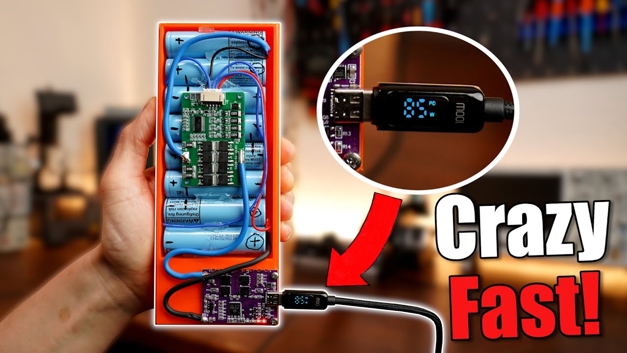
The 100W I actually found off this video: https://youtu.be/_WI9Nwqvplo
Signup for the Onshape Free Plan here: https://Onshape.pro/GreatScott
Free Altium Designer Trial: https://altium.com/yt/greatscott!
Previous video: https://youtu.be/7f8SliNGeDM
Previous Battery Pack videos: https://youtu.be/b2sBhDxmPmA https://youtu.be/hwhqn4BmC2I
You can get the shown parts here: (affiliate links)
Buy PowerBank:
Amazon.com: h...
Here's the PCB.. one day delivery for $15 for me. https://a.co/d/0gaBSmm

Continuous working current: 18A Overcharge voltage: 4.235V ± 0.025V Instantaneous current: 30A Overcharge release voltage: 4.19 ± 0.05V Charging voltage: 16.8-17V Overdischarge voltage: 2.8±0.08V Charging current: 1-10A Overdischarge release voltage: 3.0 ± 0.1V Balanced start-up voltage: 4.19 ± 0...
I'd be happy with 45 or even 30W, but all I see is these decoys, nothing I'd trust to actually be a charger
Roughly 35mm x 45mm size board
Man, the DIY scene is getting crazy

Skipped moons and planets, went straight to solar systems
Not sure if these are adhering to the spec since nowhere it actually mentions the official name of the Feature. DRP means it pretty much operates like a laptop USB-C port, disregarding the data direction.
The video showing a usecase of a powerbank is reassuring though
Yeah, he built one up with that board and tested it against the commercial one. He could only get 90W out of it, but could put more in, than the commercial one
hmm interesting...
Bit overkill for me, but not finding much luck on something in between
Sigh. Welp, making all my rookie mistakes again. Hopefully I'm getting them out of the way
Trusted the color coding on wires of a connect.. reversed the battery on my microcontroller.. burned it out
Then went to clip the leads off the Li-Ion battery, didn't about how the metal clippers will short the battery as I cut it.. battery sparked and smoked. >.<
Apparently the RC/Drone world uses the opposite polarity for their LiPo batteries ;p
On the connector
I've heard of that
You're not en EE if you've not made that mistake at least once.
Or you mean the swapped polarity between one brand and another?
Yeah. I mean, I kinda get it.. sorta.. two very different markets.. but still. They do basically the same stuff. Little electronics connected to LiPo batteries with the same connector.
More pissed that I fried both a board and a battery. Takes a while to get them shipped
I did that with a school project
With the deadline being later that week
Drove an hour and a half to get a replacement 🤣
Think I found some wires colored properly for my needs.
If it is a different market maybe do... Different colours so people dont get confused?
One of the things we started doing for our devices is built reverse polarity protection in. Happened so often that wires would get swapped
But electrically they're the same.. same batteries same voltage. Just one has the polarity flipped. I'm pretty sure the chinese did the drone ones ad didn't really care if they conflicted with the western method.. and probably didn't even care to check if someone else was using the same thing
Huh. Well, maybe the battery didn't get fried. Still reads 3.7v
https://www.youtube.com/shorts/dzf6yuWZrE8
'nuff said

so i really want to get into 3d printing but i barely no anything other than refilling the resin & Filament and where to buy the resin & Filament i donte xactly know what the best printer would be or slicing
First question is "what kind of things do you want to print?" because that mostly determines whether you should go resin or filament.
I hooked up a cooling fan for the stepper drivers, and enabled the "performance" profile...
Ladies and gentlemen, when that printer decides it wants to be somewhere, it moves
I thought it was pretty fast before.
I was wrong.
i already decided Filament as i want to print pieces for cosplay and prop's that i would like to last
main thing i decided to looked is Bambu Lab P1P

I don't think you'll regret it. I also got the Bambu. It's amazing
You would think that RatRig would have instructions for how to use the (only) filament runout sensor that they sell together with the printers they sell.
lol Of course not.
Maybe BTT has instructions for how to use their sensor with their motherboards?
Ha! Sure they do. For Marlin.
sigh
I think I have it configured correctly.
Well, mainsail seems to think it is connected and working, and I printed a benchy without anything complaining. Now I just need to induce a failure and check if it works then.
But later...
Okay, 3D printer specific question this time, promise. What kind of glues do you guys use for PLA and other sorts of material?
I'm hearing maybe like E6000 or E8000, and I also have this Gorilla Glue clear grip or something, contact adhesive.. I assume probably CA? (thin? Thick? Gel? Does it matter?) Any thoughts or others?
CA is all i use. Thick or thin depends on the situation
I am printing a HUGE boat for tabletop games (D&D, I think) for a friend, and the boat comes in 8 squarish sections per deck, and 3 full decks tall, with an additional bottom later for the hull shape, and some bits on the top. The decks magnetically stick, but I need to glue each section together
It has some pin-holes for 1.5mm or 2mm dowel rod, which will really help.. but was debating what glue is best. I've used CA a lot with my warhammer models when I want to attach non-polystyrene to stuff, or the resin models.. so I think I have all sorts around
Might need a bigger bottle for this
They're relatively flat surfaces, but it is a CF filled PLA (was worried about stiffness on such a huge thing), so that gives it a slightly rough surface
So.. kinda thinking a gel might be necessary
Anyone made threads and such in 3D prints?
Specifically, with blender?
Wondering if there's any gotchas or tricks I need to think about when designing the threads.. like tolerances or min thread sizes, etc.
Like.. how do I figure out what the smallest thread I should be making is, based on my nozzle/layer height?
i have printed threads, but i got those online. no clue what to use in blender
others here are way better with software, they ought to know
I've always used F360's thread feature...
probably best to look into M3 - M10 or whatever thread specifications - they have seemingly everything you need to know in ther
I'm not worried about standard measurements, more like how much do I need to shrink threads in the model on the female side so the male threads will fit without interference.. or, I know there's no way any printer yet can print m3 threads correctly, so how do I tell, based on the limits of my printer, how small I can print?
Like, if I know I can reliably print features of 0.1mm, how does that translate to the finest thread pitch?
I know if I tried to print threads with a pitch of 0.2, there's no way it'd work, not likely 0.3.. but rather than printing dozens of different samples to just see what works, I was wondering if there's some established guidance on how to figure those numbers
Hmm.. looking at the specs for m3, that's a thread pitch of 0.5mm. That's not bad, for a resin printer, at least
When looking at my m3 screw, the seemed a LOT smaller than that. >.>
I finally pulled up blender to rough out some dimensions, and overall shapes for my two competing ideas. Both with 21700 cells in blue in the middle.

I should also sit down and learn fusion360
But that's a whole nother project
If I start getting in to wanting properly fitting parts and clearances, blender is not the tool for that. :p
For now, I'm fine winging it
ahhh now I get what you mean - someone else can probably help with that
found this
https://all3dp.com/2/3d-printing-threads-and-screws-all-you-need-to-know/
and you could do a test print:
https://www.thingiverse.com/thing:4892124 to find out what works reliably but thats for bigger screws

All3DP
3D printing threads and screws that fit is a challenge. Check out this simple guide to learn how to successfully design and print them!

This is a print test for bolt threads created and modified in Fusion 360.
I needed a more consistent way to add threads to my projects - I used these test prints to play around with altering the standard threads generated in Fusion 360 to make them more 3D printer friendly.
https://youtu.be/JOqA2Y_5-ow
https://youtu.be/JOqA2Y_5-ow
btw if you dont want a screw made of plastic (highly suggest!) you can try printing the threads and then just screw a metal screw in, it will most likely hold more than enough, just don't expect to put giant loads on it
Thanks.. sorry, fell asleep. Or tried to.
I like how it goes through 'Here's how you do it in solidworks.. here's how you do it in F360.. if you're using anything else, go figure it out'
I'd already figured out how to create threads, so it's fine.. just amused that blender wasn't even in the list.
CA is what I used to assemble my giant 3d printed ship. holds plenty strong
I do threads in blender but its a pain in the butt to get the tolerance right. I tend to make the positive thread then use that too bool the internal thread. after that I apply the bool and go into edit mod and scale the internal faces a bit to give it some more clearence. its a guessing game because you dont have the tools to be exact in blender the way you need to be
I do some small test prints to make sure I got it right
So you just sort of oversized it by trial and error?
Also... out of curiosity, have you guys used the term FFF for a printer? This article author claims it's the only term in use now by everyone he's come across in industrial or hobby space. I'd never even heard the term.
Fused Filament Fabrication. It's the non trademark encumbered equivalent of Fused Deposition Modeling®.
because blender is for animation, modelling and visual work. It REALLY is NOT meant for CAD and only things like the recent blender CAD plugin actually make it somewhat usable as such
tell me more about this cad plugin
uhhh idk I just heard about it some places I figure just googling "Blender CAD plugin"
https://www.blendernation.com/2022/04/28/cad-sketcher-free-cad-addon-for-blender/ I think its this one
One of the best things about Blender is the community it has fostered around it, a community that, other than being proactive about helping any other Blender user in need, is dead set on extending…
May I suggest your time would be better spent learning how to do parametric cad in nearly anything else?
I know an insane person who does all their CAD in blender
Maybe now you know two

Oh, I agree.. just thought it was amusing how quietly pointed they were about it
All the stuff I do in blender I treat kinda like old-school, simple CAD. Before the concept of constraints and whatnot. Like, hand drawing, but precise dimensions.
Just found an addon called construction lines which will probably help me a lot. Also need to learn Machine Tools
There's also Fluent.. I think it's called.. which I want to try
I can alrady do parametric cad in SOLIDWORK, NX, and sketch up
You may
The thing is, I use Blender for artsy things already. So it's probably more generally useful to increase my skills at blender and modeling accurately for the more artsy things, than trying to swap between two separate programs to try and force 'the best tool for the job'. Since I really don't spend that much time doing truly parametric things, it's probably not worth the extra overhead for those few projects
I am the flip side I want to use cad tools to make artsy things because the imperfections annoy me especially on things that would normally be designed in cad
Yeah, I come from an engineering background, so blender was infuriating to get used to
absolutely same
Gf uses blender a lot. But she got used to f360 pretty quick. Now she uses both
although not sure if I can recommend F360 actually, some things with array modifiers and boolean operations are REALLY wonky
I'm planning on learning F360.. I think it'll be pretty fast for me, since I started with CAD and drafting.. and many coworkers use CAD
or 3
the problem is there are no good CAD options. your choice is either shit, or pay a subscription that would bankrupt most small nations.
My friend has probably said what tooling/plugins they use in blender. I just don't remember, we try to drown them out whenever someone asks for cad software and they pipe up 😆
if someone ever gives me an option that dosnt suck I will take it. I mean freecad is garbo, its like Blender used to be and Gimp still is. f360 is Autodesk... Soldworks costs more money a year then I fucking live on. Onshape is cloud garbo. OpenSCAD is cad for programmers and I aint a programmer.
I was about to suggest OpenSCAD... But not unironically.
It is an incredible tool for certain kinds of parametric designs, but otherwise it is utterly inscrutable.
does sketch up still exist in a civ version?
well it is clowd nonsence and from what I remember not that good
there is an auto desk clone by Dassault systems that is not to expensive mearly 100 per year
For the easy path, there exists tinkercad
if you want to make something very simple I guess
but if I am making something simple, why not just use blender?
It makes as much sense as sketch up.
eww
I really dont understand all the cloud based crap
what is the point in the program being "in the cloud" is there a reason all this shit needs to be done on servers instead of just running on my own damn computer? is it just so people can run this crap on tablets or something?
TBH, I prefer onshape over f360, mostly because screw autodesk.
And i can pull it up on both windows and linux
that is what really pissed me off about F360. when I wanted to export an STL. I had to save the shit to the cloud and wait for its slow ass servers to convert it for me. WHY? why is exporting using my own damn computer a premium feature? what do they get out of me wasting there CPU cycles?
that is what freaks me out, if I cant see how I am paying for something I get worryed
For f360 you are paying with your lock in.
Same for onshape.
They want a userbase who will then get their corporate to pay for what they are used to.
there is more too it then that. my theory is they are doing it because they are using the saved shit from there free users as training data for an AI. I know a number of places are working on 3d model generating AIs that will work like the 2d image ones
3d printing youtube channels all seem to suck now. they seem to all have either turned into Bambu channels or just shity payed "reviews"
The point is profit
yes but that is what I dont get, where are they making money by forcing you to do everything in the cloud? locking you in maybe I am just not sure that makes sense. as I said I dont like it when I cant see how I am paying for something
There are plenty of reasons to do a cloud based service. And plenty of reasons not to. The benefits of a cloud system can include simpler distribution and management of their licenses as well as maintaining their code. Supporting a handful of browsers is much simpler than supporting the nearly infinite hardware and software combinations available today. It can also be cheaper for them to provide for the same reasons. And it’s a sensible option anymore with internet access becoming so ubiquitous
Here's a benefit.. trying to 3D print stuff while traveling, and I can just run my bambu printer software and hit 'print' on my printer, and it starts right up.
Not to mention it's reliable as hell (for a 3D printer)
Orint had issues, called my brother to scrape the plate off, put some gluestick on it, and put it back in. And I was on the plane watching the print start back up
So yeah, if you want something to just get stuff made, it's awesome. If you really enjoy the maintenance and tinkering with a device that also happens to print stuff, then no, it's not for you.
That's why the Bambu is so popular. It's for all us who hate 3D printing, but we really want to make stuff that requires the accuracy and repeatability of a computer-manufactured part in some aspect.
sounds kinda like the thing for me tbh
I really did not like 3D printers.. but wanted to make little detailed model parts for kitbashing. So I got a resin printer. It was messy as hell, but nice parts.. but so much work and mess, and so many print failures, I rarely used it. Got an inexpensive FDM printer.. but quality was meh, and so much work to do basic things.. but I took a leap with the Bambu and it's been outstanding. I've made so many things.. and even useful stuff now.
It's changed my outlook on making things, or even just stuff around the house.. like cupholders on the couch being the wrong size. Well, I could just make a quick adapter.. or battery holders for the battery drawer.. normal 'I can 3D print stuff', but I never would have gone through the hassle if the printer weren't so easy.
Don't get me wrong, I've had a few issues.. like the nozzle got bent once.. took me a while to figure out, or the connection to the spool seems flakey, so I need to fix that. But compared to the other printers I've had, that's peanuts.
how do you bend a nozzle?? like daaang
I have no idea, but it was bad.
The whole extruder bent like, 10º

Was covered with melted nylon all around the top. I couldn't bend it with a pliers.. wondering if the nylon insulated it so well it started to melt or something
Not sure how the nylon got all up there to begin with
Pretty sure it was nylon, at least.. rather than the PLA
bent nozzles are more common then you might think.
(it's not the extruder, the extruder is the bit that feeds the filament in to the hotend. That is the hotend. Bent at the heat break, which separates the heater block from the heatsink)
Nitpick aside.. dam that must have been a hard crash
I would think so, but I didn't see any signs of a crash.
I don't know when it happened.
Prints had been screwing up for a while.. like a couple weeks, before I noticed it.
my understanding is that generally you get a clog and the pressure of the molten fillament (that can be VERY high) pushes the nozzle assembly right out of the print head and then it crashes
The extruder should typically skip well before that point, they can only apply so much force before literally stripping the plastic 🤔
I guess it could have crashed into the model at some point. But there's no damage on the plates
not always. and even if it starts skipping some it might not skip enough to stop building pressure
also because its clogged the heat has no where to go, the glob of goo gets hotter and expands even more adding to that hydrualic pressure
at least that is what I think happens in cases like that or at least one of the things it might be. few other people here that know allot more about this stuff that might know better
I seem to have been very lucky with my printer so far. no crazy fails like that yet
other then a corrupt SD card giving me horrible blobbies all of my fails have been minor and my fault
Other than this weird thing which I think is a loose cable, and a few issues where I think the gcode is messing up, it's been real good
And that one catastrophic failure with the hot end
But even that.. it was still managing to print sometimes.
Trying to troubleshoot what I think is a slicing error from the other side of the country.. my brother cleans it off, looks at the part, then I fiddle with settings and hit print, then watch it remotely on the camera.
Works a lot better than I expected, given my experiences with other 3D printers
I hope they make a resin printer soon.
Or.. even better, something new that can do the same kind of small, detailed parts ;p
why dosnt prusaslicer have built in temp tower generator? test prints like that should be built in, I hate having to do custom gcode shit
temp tower as in single layer hull around the print to keep heat in?
think that is a draft shield or something. I mean a temp test tower for figuring out the ideal temp to print a filament at
https://cdn.discordapp.com/attachments/1132869184095780914/1179649113348902984/IMG_20231129_230114622.jpg?ex=657a8cd9&is=656817d9&hm=e4be432926ad67f46f2d45d378a24ca4ad0a95ff2c196216779c5c8fda2e284e& https://cdn.discordapp.com/attachments/1132869184095780914/1179649112065462323/IMG_20231129_230131005.jpg?ex=657a8cd9&is=656817d9&hm=38a8590b02728d57473584c4773d36865587eecd29345e3e31b3bc1d163b214d&


they look exactly the same! I cant see any difference at all other then a slight bit of droop on 225
how the hell can it all look the same across that big of a temp swing? and I watched the nozzle temp, it changed when it should, I got my G code right
Good material properties?
I have had temp towers where only like one layer came out slightly wonky.
I guess its just good filament that dosnt really give a shit what temp you print it at?
And other filaments where only one layer looked good.
I was told that because this is white I might need to boost my temps a bit more, I guess titanium dioxide is fairly good insulator.
also didnt notice much if any change in layer str when breaking the little spikes.
I was hoping I could improve my bridging and overhangs a bit with adjusting the temp but this gave me nothing to work with.
"When printing in performance mode the stepper drivers must have active cooling!"

So I added a fan mount
Also, the (currently janky) dehydrator is a complete success. I was able to take very brittle 2-3 year old PLA and make it flexible again. Took about 3 days with the dehydrator set to 110F. Who knows what it actually was putting out.
"Damn filament runout sensor, I thought I fixed that damn false positive issu... Oh. The spool jammed."
sounds like it worked like intended
Yup. Its one of the fancy kind that senses if filament is moving or not, and it took a little tuning to stop it from getting false posatives. But considering that the only trigger for a few days now was legit I think I got it.
Yeah, the ones that detect movement can be really finicky
that looks like a very good fan mount to me
you could always upgrade from a box mounted fan to a full box fan
as that would also cool the PSU and everything else
Anyone have an idea how to fix this? The walls don't adhere to the bottom layers, also the bottom and top layers look pretty under extruded. Is it a clog?

I would recalibrate the first layer to be closer to the build plate but I literally only printed two things on a printer that isn't mine :p
Also maybe higher nozzle temp?
It also seems inconsistent over the surface to make sure everywhere is levelled
i was just thinking, this started when the slicer updated
i'll try some tests prints with different z levels

a releveling wont hurt anyway
Red is not good (too far away imo), green is a good area. I dont know how yellow happened but it looks good
Even tho it is right next to red
your printing fast right?
250mm/s
what temp are you printing at?
220C
PLA?
yes
hm, that should be hot enough...
rest of the print looks fine, it's just the bottom and top layers
walls are fine
Like, i just printed this yesterday, looks pretty good to me

I mean it dosnt look horrible but I think it should have more squish then that
oh that looks sweet

exactly my thoughts
have you done a calibration cube? the ones you use to check that your walls are as thick as they should be
maybe you need a little boost to the extrusion multiplier
Not yet, actually never done one😂
I had to boost it on my printer a little bit. I needed 102% to actually get the target wall thickness.
I did up the flowrate but it didn't help
what slicer are you using?
you might just need to slow down your first and top layers a bit
Elegoo's slicer, not by choice btw
They dont allow ultimaker to have a profile for their printer
And i tried importing a profile i downloaded into ultimaker but it didn't work
Its an adaptation of cura
is it even updated to cura 5? if one that came with my neptune 3 pro was 4 and cura 4 dosnt even have arachne
I'll check in a moment, not near my computer atm
eww, its 4.8.
Yeah I'm not happy with it
I would make your own profile in Cura 5.2 or what ever its up to now. if that is the slicer you like anyway. you can just copy the settings over even if the import/export stuff isnt working

UltiMaker Community of 3D Printing Experts
I wanted Tree supports and all the extras that came with Cura 5.4 but was apprehensive about moving away from the 4.8 Elegoo provided for fear of messing things up. My new Neptune 4 is rock solid now and printing amazing prints so I finally took the plug and did it. I couldn't be happier. So here...
I had to do that with mine as well. it was a headache because I coudnt get the retraction settings right for some reason. took some dialing in but I think the retractions that came in the stock profile were just bad to begine with.
hopefully its less annoying with the 4
oh, I think prusia slicer might have profiles for them now
Yeah. I don't think the neptune 4 pro profile will ever come to cura
where did you hear they dont allow it?
Well they wouldn't have built their own software for it otherwise, me thinks
na, it jsut takes time before the slicers actually update to add them. took about 5 months before offical profiles got added to prusa and cura for the 3.
found a video saying that they had submitted them. who knows how long until they are actually added. Prusa is starting a new alpha test and I bet those will have the new profiles in them. not sure what is taking Cura so long as it looks like they just had an update
Guess I'll just have to wait. I'll set up a custom profile until then. Will also do a relevel
Ahah, Uncle Jessy the Elegoo shill has profiles on his youtube page I think.
I found a reddit post with an entire guide
oh nevermind... eww. he only has the profiles on his patrion
Tried increasing the flow a tiny bit?
Wow, so late
yeah, like 10%
I suspect you just need to slow down the top/bottom layers. those are cosmetic areas of the part and if there speedy profiles are not tuned to make them look good and instead just go for speed numbers they wont look amazing.
Assuming esteps are correct, that looks like it need extrusion multiplier tuning.
calibrating esteps and PID tuning only needs to be done if you replace the relevent components. its done from the factory and actually done correctly, unlike the nonsense 90% of the guides out there show.
I've had it for a few months now, printed like 30 prints on it, it shouldn't need calibration.
It slows the first layer by default, i think it prints it at like 60mm/s
60 is still fairly fast for a first layer and top layer.
I would set first layer and top solid infill (not sure what that is called in cura) to 40mm/s and do a small test print.
it wont add much time to most prints
also something I read. the speedy profiles for the neptune 4 are going to be tuned to the high flow PLA they sell. so you might need to do some adjustments to get it to work well with normal PLA. heard something similar with bambu.
unless that is what your using. I question if its worth it, a good hotend should be able to keep up with those speeds without special filament assuming the profile is tuned correctly for it
I have used elegoo pla, but not the fast flow filaments as they're way more expensive. Its just baffling me a bit as the first prints went absolutely fine and now it's doing this
hm... if its a new problem maybe you do have a bit of a clog. but I would expect that to show up more on walls then on tops
you are printing at the upper temp range for PLA. I guess it could be causing some kind of build up in the nozzle or something. really not sure
I did do both a hot push and a cold pull, but maybe i just need to take the nozzle out. It sucks as i don't have many spares and elegoo doesn't sell them yet 🙃
Did find some on AliExpress, but that'll take a while to arrive
well they do sell them... in the stupidest fucking way they can. you have to email them and they will tell you how to get replacements from them. and they are kind of exspensive for simple brass nozzles
this slightly shorter volcano nozzle crap is really dumb and allot of companies seem to be doing it. it makes no sense, volcano is opensource! they can just use those and make replacements easy
but gread
lol, I am still on my first nozzle. 14kg of filament in
no idea when I should replace the damn thing
I clogged a few on my Ender, but those were so cheap i didn't even bother unclogging them, just threw in my scrap pile
Extrusion multiplier need to be tuned per filament type.
Just put a volcano nozzle in and let it stick out a little? Assuming the threads are the same, that should work fine.
To be really extra use a bit of copper to make a washer to extend the heater block like a rapido UHF does.
can anyone tell me why this keeps happening? the angle of the overhange is like exactly 45 degrees. there is no reason an overhange like that should fail. yet I keep seeing this especially if I print something like threads. and look at the other part that was printed with it, at exactly the same height there is something odd in the surface of the outter wall. its like its slightly buldged out there, maybe over extruded?


wait what is is supposed to look like? just round with a key?
like can you share the gcode vis?

does this happen regularly?
the one example I can find looking for this in google, everyone says its poor layer adhesion. slow down parimeters, increase temps. I am printing PLA at 215 and my outer perimeter speed is 30 mm/s and this part is so small there is no way its getting close to that speed. its also printed a 0.18 layer height.
yes
if I try to print a threaded hole or any similar shape, a hole with a bit of overhange in it. this will happen at some point
I could imagine that it for some reason underextrudes while having lower nozzle temp so it kind of doesn't stick to the previous layer while being torn off it until it magically works again
and I dont mean steep overhanges, 45deg at most
have no idea why that would happen tho
ohh wait this is happening at the first layers of the overhang, right?
no, it happened across the entire length of that overhange
like every layer had that from 219-226 had that delamination
hmmm... I wonder if there could be a twisting motion at the nozzle... is it always facing the same orientation?
I dont know
I guess the cause is the first layer that goes wrong like that
its really pissing me off, the type of stuff I print nearly always has these types of overhangs on hollow parts like this. I need to be able to print them reliable
and i dont understand how this can be under extrusion when I have a clear sign of overextrusion in the same print on the other model
solid cylinder next ot it. 3/4 the way up you see a ring, that ring is not part of the model. that layer is just thicker then it should be and I dont know why
What is the feature at the exact layer the effect/whatever happens?
And if you set your slicer to flow/speed do you see a change in colour on that layer? Similarly you may see a change in line thickness if using arachne

So it's happening when the features being printer change. Slicer dependent: you sometime see a change in speed for the entire layer when the features change. This can cause a change in flow rate, which can have an effect on both surface finish and total amount of plastic extruded
and its printing that at 17/mm/s so basically the slowest part of the print

Never suggested it would be near the limit. Actual flow relative to speed decreases as print speed increases due to things like nozzle back pressure. It's one of the reasons bigger nozzle sizes can print quicker, and why 0.2/0.25mm nozzles need to print so slowly
but still, this is slow and low flow. everything I can find say "your printing to fast" but its not, or the layer height is to high, not enough flow, not enough heat.... I dont understand
its slow, its hot, its well within normal flow range your my nozzle and extruder, the layer height is small its only 0.18mm!
this is after bumping my printing temp up from 205 to 215. I thought that might help with this kind of problem. I see signs of poor layer adhesion in other places as well
I'm also not talking about printing too fast. This is a phenomena at every speed to some degree.
Regarding the stringing from the internal overhang, that is unfortunately normal with internal circular features, and has happened every single time I have printed internal threads vertically. I assume that because of the circular motion the print head is essentially continuously pulling the fresh filament away rather than sticking it down. Like if you pull on something that you just glued down
worst part is its a repeating feature on that part. it printed that exact overhange 2x perfectly then screwed it up on the 3rd.
Well, now I know why my first layers were kinda shit. My z offset was off by almost 0.2mm
Remember kids: When changing the nozzle always redo your z offset, and the paper method doesn't work for a .6 nozzle
heh I learned! :D
I have a set of gauges and I'm gonna use em, screw paper😂
I took my nozzle out for cleaning because it was leaking, and didn't redo the offset afterwards.
This calibration is gonna be wasted though. My diamond nozzle arrives later this week.
Guess I'll find out if all the hype about how awesome they are is true.
How's it going in here
problem with stoopid stringing
the paper method doesn't work for a .6 nozzle
please explain?
I've heard that's a common problem on interior circles in certain conditions.. I think a printing for mass production channel went over it. I'd have to do some digging to find it
I think he added a little corrigation on it, maybe? I can try to find it
One thing I'm seeing is just reduce the inner wall speed down to like 10mm/s
The other is zig-zag the interior wall to make sure they stick, which could help with tolerance if you're trying to fit something into it.. also looks a little more interesting. But, might not be what you want.
I'm looking into the same thing to print some interior threads at some point
Mostly troubleshooting
zig-zag? do you mean with fuzzy skin or something? I mostly print molds and mold shells so I need smooth surfaces.
speaking of smooth. does anyone know if there is a way to smooth a TPU print to get rid of layer lines?
Ok, so a common quick and dirty method to get close to a good z offset is to use a piece of normal paper like a feeler gauge. However that is for 0.4 nozzles with 0.4 nozzle layer heights, like say 0.2mm. Where the "normal" layer height for a 0.6 nozzle is 0.3mm and so if you were to use the paper method to get a starting point you would need to adjust more than normal to get a good first layer.
Or at least that is how I have found it. Maybe I'm just doing it wrong.
So a set of feeler gauges would help🤔
Oh, 100%
Yeah, I use feeler gauges.
that dosnt sound right at all...
It's literally in the ender guide
that makes it even more sus
A releveling and some minor z-axis adjustments seemed to have fixed most of my issue
Maybe the bed springs loosened a bit or something with use and temp differences, causing the bed to go wonky
still dont get why they added those back in. they are pointless. the SV07 comes with the option to hard mount the bed or use springs. thing that is a better way to do it. use the springs if you find you bed is more warped the autoleveling can really fix and if not just hard mount it (the Neptune 3 pro is hardmounted)
My damn hotend filled its sock with goop a couple of days ago, so I removed the nozzle, cleaned everything and carefully reassembled making absolutely sure the nozzle was well seated.
Today it did it again. Much cleaning later, I'm running it sockless so I can see if A) it leaks again and B) where in the hell it is coming from.
No leaks yet. I have to re-sock it now so I can run the part cooling fan, so it will probably start leaking again knowing my luck.
Also, fuck Discord with a rusty pole. I know diamond back nozzles are sexy, but the image is not explicit.
This thing ships in a snazzy aluminum case.
I'm not gonna install it until tomorrow though. It deserves an actual wrench not a vice grip.
I offered to print this massive ship for tabletop gaming.. like, spelljammer sort, it seems. But it's huge. Like almost half a meter long, 30cm wide, and .. I don't know, probably close to half a meter tall? Maybe 40cm? Split into 34 parts (all for a 20cm-ish square bed). I've learned a LOT about 3D printing working on getting this all done.
Had to learn how to do overhangs and supports, then support materials, cut and print failed sections, how to handle pillowing, bed adhesion, ironing, surface finish, nozzle sizes, you name it.
How to send prints from the plane.. >.>
I'm printing this thing (at 150% size), and it is cool as hell.

The tolerances are all supposedly 0.2mm but I can just do that with a 0.6 nozzle at 150% without too much trouble with fusing. Most parts are coming out fine. I did break the first boom I printed trying to get one of the joints to come loose, but all other parts (that I have done) have popped apart without too much effort.
I was never able to get my old printer to not fuse the hell out of similar stuff, and it would have taken a week to print probably.
With the new one the only limitation is how much first layer risk I want to take (lot of small contact patches == lots of places to fail) and how many colors I want to use.
With a single color and at 150% I could fit the whole thing on the build plate as a single print if I trusted my bed adhesion that much
And it's not a small toy

I kinda want to do one at 200% after this one.
I was requested another phallic dinosaur, so it's currently printing
what is a phallic dinosaur?
I want to make a 3d printed RC tank. I am not sure if I want to use someone elses model or design my own.
My printer decided it wanted to print spaghetti 🍝
ouch... well at least that means dinner is sorted
any idea why it did that?
Part of the tail let go of the build plate, took the rest with it
oh no, not the dickosuarus!
I use a brim for almost everything. does make cleanup a little more annoying but it helps allot
Yeah I'll try a brim

That's pretty neat!
looks nice!
is it feasible using a good 3D printer and modifying it yourself so it can also accept a cnc milling head?
I really like the idea of the snapmaker 2 but not its price and the proprietarity
Not really. Milling puts a lot of force into the gantry, and printers are specifically designed to have as little weight as possible in that area.
Even a simple CNC router will tend to have a beefier gantry than any printer would.
You can build a CNC router with much the same design and many of the same electronics you could use for a printer, but it will need to be stronger.
Unless, maybe, you have a well built donor printer and you use something dremel-sized.
well the snapmaker has a dremel-sized "CNC" or rather they have interchangable cube modules of roughly the same weight...
it do be slow tho
That sounds like a great way to have a machine that isn't really good at anything.
yeah true...
For me, any CNC router would need to be able to fit (at least the width of) a standard sheet of plywood.
And a milling machine would need to be... An actual mill.
I would probably use it like a 3D printer but with metals and similar.. also for mechanical things but no really big ones
so the issues is the forces in milling that make a light (fast) 3D printer impossible
yeah you cant really combine the 2 in a good way. the lateral forces on the tool head a very high with CNC so the whole thing needs to be rigid as hell. most of the small desk top ones it seems are not really anywhere near rigid enough. its actually stupid that they are not because it wouldnt be hard or that much more exspensive to make them right. no matter what even the lighter crappy ones are still way heavier then a 3d printer so it would be printing slow.
now 3d printer and laser is no problem to combine
hmmm aight thanks for the input!
I am amazed that fiber lasers are actually coming down in price to the point where they are starting to become practical! those things can do so much, the tech behind them is incredible. I bet in a few years you will be able to get one for under a thousand bucks
the small desktop cncs I have seen can barelly handle soft woods and cant do anything with soft metals. I really want a little CNC that can do aluminum and brass. there are small ones that can do those just fine but its always the next step up in size and at that size I am not sure I would really call them desktop anymore.
hmmm I see
This. Mills and printers are built with diametrically opposed structural needs.
A diy 3018 CAN do those... Slowly and gently.
But a CNC EDM is certainly possible to build from a 3d printer motion system
Oh yeah, EDM is something you can do nowadays. There are good resources out there on how to make a machine, and you can even get ready to go pre made boxes nowadays.
but as a former goth kid I have to say I like EBM much more then EDM
Damn it. Every. Single Part. broke free perfectly. Every joint is stiff but smooth. Everything has clipped together perfectly so far.... Except for two joints on the boom.
Multiple reprints, and they all have exactly the same issue.
There are only three joints printed in this color, and two of them fail consistently, I wonder if it is specific to this roll/color? I'm gonna try applying -0.01mm of XY Compensation and print it again.
Even the undercarrage, which I thought was going to fail to break loose for sure popped free with minimal effort.
Good news! Everything seems to break free perfectly.
Bad news:

There was some layer shift. Oh god.
I have never had layer shift before, on any printer. I wonder WTF happened here?
Gonna check belt tension quick I think.
that all print in place?
Yeah.
It is the excavator boom. The part closest to the camera folds over and clips together to make the main boom, and the post farthest out gets pulled upward to pop into place and become the hydraulic cylinder for the stick.
that is a cool model... tempted
Oh it is an awesome model. It is a mix of print in place assemblies and clip on parts. Everything moves, no glue is needed, and you can get a nice multi-color design on any printer.
god, the bambu superiority is strong in the description
So far I have printed 4 of the damn boom though, and they keep failing in interesting ways.
what are you printing it out of? its all snap fits and snap fit never seems to work amazing with PLA. probably the biggest reason for me not to waste the filament on it
Polymaker PLA+
The other parts all worked fine, but the boom likes to fuse on me.
Then this one, with XY compensation applied, layer shifted.
I wonder if there is an easy way to make the arm posable
If you did something to adjust the friction in the hydraulic cylinders it should be possible.
I wonder if my nephew is old enough for one of these... and if I happen to mess up a few parts and end up with 2 of them one as a test, well that wouldnt be so bad, right?
Once I get this one done, I'm gonna try one at 200% size 😛
I only ever have one color of filament on hand and this dosnt seem like it would be easy to paint and I dont know how to paint something to make it kid safe.
I have.. once.. when I reached in and tried to yank an errant string of filament out of the way, and the print head swung over at the same time and I knocked it good. Layer shift. >.>
Acryllic
In fact, thick acrylic gel, paste, etc are good to try and hide layer lines or things like slight shifts. Builds up well, it's actually a kind of glue, and you can get it in all sorts of consistencies and flavors. Non-toxic, as well.
Unless you count micro-plastics. >.>
But you can get all sorts of acrylic mediums at any art store, amazon, etc. Anything with a reasonable supply of aryclic paints for fine art. Modeling stores will have similar stuff, but likely way more expensive, and a lot harder to understand what it is. ;p
In other news, finaly gluing this massive 3D printed ship together. Using some wooden q-tips as rods in pre-printed holes between parts. And a tone of super glue gel. Even started slathering it over and into the gaps like forbidden spackle.
Well, I started the print again, and got another layer ship by the same amount on the exact same layer. So I'm betting something is wrong with that gcode file.
Despite the quality issues of the bottom layer, the print still functions as intended. We designed this frame to mount two 70mm server case fans in the bottom cableway of my patch cabinet (all the cables exit via the top one)

@calm mulch
Uhhh that's not the link I meant to send...? Where does that even come from🤔😂
I meant this one of course!

The US companies Avante Technology and Mind in a Box have published a software solution for converting common 3D printing file formats such as STL into the ISO standard format AMF (Additive Manufacturing Format). According to the manufacturer, the application called AMFsample, which is available as open source code, enables the ISO standard inte...
Well, I hate to tell the ISO this, but STL is already standard enough that they are gonna have a very, very uphill battle.
they do seem a little late to the party
are there maybe some fancy industrial printers that only use that formate?
If people really want to use an ISO standard format for some reason, well STEP exists.
Except the only thing STEP has going for it is that is is somewhat widely supported and it gives you a result that can be edited reasonably. The format itself sucks.
for some reason I decided I needed a deathclaw... https://cdn.discordapp.com/attachments/231590159420882945/1185366034476171345/image.png?ex=658f5925&is=657ce425&hm=90469c7d15a85afdbeb2cc4ce34957df5fe9978184786fd161cd7512af096f3c&

more photo fails from pilfit! https://cdn.discordapp.com/attachments/231590159420882945/1185760860833067058/image.png?ex=6590c8db&is=657e53db&hm=379fd82d4cd650dab0732cc46b85e39d6ef00a51ebd33f8313243e2b26bf4e9d&


nice
Not as bad as STL sucks. STL is literally the worst way to represent 3D geometry without being actively malicious. That said, I really thought AMF died years ago. 3MF is the way for mesh data anymore, with Step being pretty decent for CAD data interchange. Too bad NX and CATIA both have frequently bad STEP exports due to loose tolerances on their internal surface definitions.
I've also been able to do some fun personal printing lately:


what is it?
An inconel bowtie. The knot area is hollow for a plastic adapter that lets me put in an elastic bowtie clasp like on the pre-tied ones. Shitty plastic mock up here:


heh, neat

what is wrong with STL?
I am guessing your problem with it is that its a vertex based format. and its fine for that, dosnt bother with any other unneeded data for things like 3d printing just the basics so the files are fairly small and widely compatabile... yeah its not good for curves but if you need super accurate curves then its simply the wrong format not a bad format.
I think something like a vector-based format would be great for down and upscaling
It has no units, no metadata, and no vertex - triangle associativity. It's a bag of triangles and nothing more. It's inefficent to store, inefficient to read, and inefficient to work with. Its only advantage is that it was something simple for a non-programmer to write in the 1980s
my questionable painting skills, this is the first model I have tried painting and I dont have good hand control. https://cdn.discordapp.com/attachments/231590159420882945/1186093368216916068/IMG_20231217_174937780.jpg?ex=6591fe87&is=657f8987&hm=e549d04024715c0061254a9c24fad6d722681aad11318158008f880567434cdf&

it also glows in the dark... https://cdn.discordapp.com/attachments/231590159420882945/1186087367266816071/image.png?ex=6591f8f0&is=657f83f0&hm=ab900dc5ed78870b8c88e1fa70b85a779ebaf0d71f45be2a0242455d288d52b7&

why inconel that stuff is worth its weight in gold?
I dont think inconel its self is all that exspensive... its more that its stupid exspensive to have anything made in it because its so hard to work with. I guess if your already 3d printing metals and it can do it, its not all that big of a difference?
at least the stuff that go's into it isnt all that rare.
no its both it is a PITA to work but is is a patented hyper special stainless steel so it is also stupid expencive
IN718 is a nickel alloy, not stainless steel. It's only about $25/lb, for the powder, which is not that much of a % of final part cost typically. Anyways, we occasionally get to run fun parts like this during demos and other events. If I were paying for it, I'd get it printed in titanium, would cost about the same but weigh half as much.
My z offset is drifting? I'm pretty sure the probe is solidly mounted, and yet my first layers keep getting thinner. This is gonna be fun to diagnose.
I have heard it can happen if the probe is mounted at a slight angle
I think I'm gonna make sure the probe (a superpinda) is actually as solid as it feels, then check to make sure the nozzle isn't trying to do anything funny.
As long as everything is working, this thing prints really fast and nice, but between the prints come the problems. Holy shit, so many problems. And new ones each time. Generally once they are fixed they are fixed, but it keeps finding new and exciting ones.
I need to get one of those "Stand back, I built this shit myself" Voron signs, and replace the logo with a rat rig logo.
Except it would be a genuine warning
Someday, I'll have everything all perfectly in tune and adjusted to where it stops acting up, but until that day I tinker. Constantly.
I don't regret buying what I bought, but sometimes when it is being a little shit I tell myself that I could have had an X1C with AMS (I don't actually want an X1C with AMS except maybe as a second printer)
I'm betting that these two screws just being loose inside the hotend sock isn't normal

Needless to say, the toolhead is coming apart and I'm gonna so some hotend surgery on my desk.
Two of the three screws that held the hotend onto the heatsink had completely walked out, and the third was hanging on by a thread. I'm gonna tighten the bejesus out of these things, and reinstall.
"Those are extra parts" - Shack probably
high speed printing with input shaping is allot of vibration. guess it might need high temp thread locker? do they make thread locker that works at those temps? stuff for engines probably isnt ment for pushing 300c
I would guess you cant just crank down on them more, I am assuming those threads are in copper or aluminum so easy to strip
They seem to be in what looks like the tiniest possible inserts I have ever seen. Also, there is a grub screw that holds a clamp against the heatbreak tube that wasn't very tight.
So everything is nice and snug now.
If it starts to walk loose again I'll have to locktite it.
might be tricky with the temperatures
don't know of any but 3m probably makes something for that :P
there is stuff in the auto world designed of exhaust components should not be an issue
I would like to fucking murder anyone that's put a threadlocker on an exaust component. Fucking hard enough taking that apart without bolts busting.
is there any point trying to remove an exaust bolt with a wrench? makes more sense to just reach for the grinder to start with
guess with manafold bolts you dont have a choice
well studs/nuts
penetrating oil, heat, wrench, works more often than it doesn't in my experience.
The threads are in the "cold side" of the hotend, so plain ol' loctite should be fine.
I am not sure if I just made a great purchase or if I just did something horribly wrong. I just purchased an elgoo saturn 3 ultra because it was on sale. that makes 2 resin and 2 fdm printers so far. I might have a problem.
Print a solution
Up side, printing more miniatures will not take as long now.